1
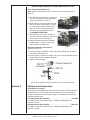
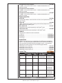
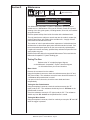
Millermatic Compatible™
Owner’s Manual
Product:
Python
Manual:
091-0593
Serial:
08050001
Voltage Rating: 24 VDC
Revision:
May 2008 Rev B
Gun models:
240-8xx
225 Ampere Push-Pull Welding Gun
Table of Contents
Safety Considerations.........................................................................i-iii
Installation................................................................................ Section A
Technical Specifications......................................................................................1
Support Equipment Required..............................................................................1
Gun Lead Connections.......................................................................................1
Coolant Recommendations.................................................................................1
Operation..................................................................................Section B
General...............................................................................................................2
Controls and Settings..........................................................................................2
Trigger Adjustment..............................................................................................2
Drive Roll and Idler Rolls....................................................................................2
Accessories..............................................................................Section C
Insulated Drive Roll Kits......................................................................................3
Replacement Kits................................................................................................4
Snake Skins........................................................................................................4
Contact Tips........................................................................................................4
Barrels.................................................................................................................4
Maintenance.............................................................................Section D
Periodic Maintenance.........................................................................................5
Recommended Spare Parts List.........................................................................6
Troubleshooting........................................................................Section E
Troubleshooting Guide........................................................................................6
Testing The Gun..................................................................................................6
Appendices...............................................................................Section F
Diagrams / Parts List...........................................................................................9
Mechanical........................................................................................................10
Electrical...........................................................................................................17
Warranty
Declaration of Conformity for
European Community (CE) Products
Note
This information is provided for units with CE certification (see rating label on unit).
MK
MillerProducts,
Electric Mfg.Inc.
Co.
Manufacturer’s Name:
1635 W.Armstrong
Spencer Street
16882
Ave.
Appleton,
WI
54914
USA
Irvine, CA 92606
Manufacturer’s Address:
Declares that the product:
®
XR-Control
Python
conforms to the following Directives and Standards:
Directives
Low Voltage Directive: 73/23/EEC
Electromagnetic Compatibility (EMC) Directive: 89/336/EEC
Machinery Directives: 89/392/EEC, 91/368/EEC, 93/C 133/04, 93/68/EEC
Standards
Arc Welding Equipment Part I: Welding Power Sources: IEC 60974-1
(September 1998 – Second Edition)
Arc Welding Equipment: Wirefeed Systems: IEC 974-5
(September 1997 – Draft Revision)
Degrees of Protection Provided By Enclosures (IP Code): IEC 529:1989
(November 1989 - First Edition)
Insulation Coordination For Equipment With Low-Voltage Systems:
Part I: Principles, Requirements and Tests: IEC 664-1: 1992
(October 1992 – First Edition)
Electromagnetic Compatibility, (EMC): EN 50199
(August 1995)
Torches And Guns For Arc Welding, EN 50078
SECTION 1 – SAfETY PRECAUTIONS - READ BEfORE USING
som _nd_7/02
1-1. Symbol Usage
Means Warning! Watch Out! There are possible hazards
with this procedure! The possible hazards are shown in
the adjoining symbols.
This group of symbols means Warning! Watch Out! possible
ELECTRIC SHOCK, MOVING PARTS, and HOT PARTS hazards.
Consult symbols and related instructions below for necessary actions
to avoid the hazards.
� Marks a special safety message.
� Means “Note”; not safety related.
1-2. Arc Welding Hazards
� The symbols shown below are used throughout this manual to
call attention to and identify possible hazards. When you see
the symbol, watch out, and follow the related instructions to
avoid the hazard. The safety information given below is only
a summary of the more complete safety information found in
the Safety Standards listed in Section 1-4. Read and follow all
Safety Standards.
� If earth grounding of the workpiece is required, ground it directly
with a separate cable.
� Only qualified persons should install, operate, maintain, and
repair this unit.
� Wear a safety harness if working above floor level.
� Keep all panels and covers securely in place.
� During operation, keep everybody, especially children, away.
� Clamp work cable with good metal-to-metal contact to workpiece
or worktable as near the weld as practical.
ELECTRIC SHOCK can kill.
Touching live electrical parts can cause fatal shocks
or severe burns. The electrode and work circuit is
electrically live whenever the output is on. The input
power circuit and machine internal circuits are also
live when power is on. In semiautomatic or automatic wire welding, the
wire, wire reel, drive roll housing, and all metal parts touching the
welding wire are electrically live. Incorrectly installed or improperly
grounded equipment is a hazard.
� Do not touch live electrical parts.
� Wear dry, hole-free insulating gloves and body protection.
� Insulate yourself from work and ground using dry insulating mats
or covers big enough to prevent any physical contact with the work
or ground.
� Do not use AC output in damp areas, if movement is confined, or if
there is a danger of falling.
� Use AC output ONLY if required for the welding process.
� If AC output is required, use remote output control if present on
unit.
� Disconnect input power or stop engine before installing or
servicing this equipment. Lockout/tagout input power according to
OSHA 29 CFR 1910.147 (see Safety Standards).
� Properly install and ground this equipment according to its
Owner’s Manual and national, state, and local codes.
� Always verify the supply ground – check and be sure that input
power cord ground wire is properly connected to ground terminal in
disconnect box or that cord plug is connected to a properly
grounded receptacle outlet.
� When making input connections, attach proper grounding conductor first – double-check connections.
� Frequently inspect input power cord for damage or bare wiring –
replace cord immediately if damaged – bare wiring can kill.
� Turn off all equipment when not in use.
� Do not use worn, damaged, undersized, or poorly spliced cables.
� Do not drape cables over your body.
� Do not touch electrode if you are in contact with the work, ground,
or another electrode from a different machine.
� Use only well-maintained equipment. Repair or replace damaged
parts at once. Maintain unit according to manual.
� Insulate work clamp when not connected to workpiece to prevent
contact with any metal object.
� Do not connect more than one electrode or work cable to any
single weld output terminal.
SIGNIfICANT DC VOLTAGE exists after removal of
input power on inverters.
� Turn Off inverter, disconnect input power, and discharge input
capacitors according to instructions in Maintenance Section
before touching any parts.
fUMES AND GASES can be hazardous.
Welding produces fumes and gases. Breathing
these fumes and gases can be hazardous to your
health.
� Keep your head out of the fumes. Do not breathe the fumes.
� If inside, ventilate the area and/or use exhaust at the arc to remove
welding fumes and gases.
� If ventilation is poor, use an approved air-supplied respirator.
� Read the Material Safety Data Sheets (MSDSs) and the
manufacturer’s instructions for metals, consumables, coatings,
cleaners, and degreasers.
� Work in a confined space only if it is well ventilated, or while
wearing an air-supplied respirator. Always have a trained watchperson nearby. Welding fumes and gases can displace air and
lower the oxygen level causing injury or death. Be sure the breathing air is safe.
� Do not weld in locations near degreasing, cleaning, or spraying operations. The heat and rays of the arc can react with vapors to form
highly toxic and irritating gases.
� Do not weld on coated metals, such as galvanized, lead, or
cadmium plated steel, unless the coating is removed from the weld
area, the area is well ventilated, and if necessary, while wearing an
air-supplied respirator. The coatings and any metals containing
these elements can give off toxic fumes if welded.
OM-1594 Page 1
Millermatic Python® Owner's Manual Page ARC RAYS can burn eyes and skin.
Arc rays from the welding process produce intense
visible and invisible (ultraviolet and infrared) rays
that can burn eyes and skin. Sparks fly off from the
weld.
BUILDUP Of GAS can injure or kill.
� Shut off shielding gas supply when not in use.
� Always ventilate confined spaces or use
approved air-supplied respirator.
� Wear a welding helmet fitted with a proper shade of filter to protect
your face and eyes when welding or watching (see ANSI Z49.1
and Z87.1 listed in Safety Standards).
HOT PARTS can cause severe burns.
� Wear approved safety glasses with side shields under your
helmet.
� Use protective screens or barriers to protect others from flash and
glare; warn others not to watch the arc.
� Do not touch hot parts bare handed.
� Allow cooling period before working on gun or
torch.
� Wear protective clothing made from durable, flame-resistant material (leather and wool) and foot protection.
MAGNETIC fIELDS can affect pacemakers.
WELDING can cause fire or explosion.
Welding on closed containers, such as tanks,
drums, or pipes, can cause them to blow up. Sparks
can fly off from the welding arc. The flying sparks, hot
workpiece, and hot equipment can cause fires and
burns. Accidental contact of electrode to metal objects can cause
sparks, explosion, overheating, or fire. Check and be sure the area is
safe before doing any welding.
� Protect yourself and others from flying sparks and hot metal.
� Do not weld where flying sparks can strike flammable material.
� Remove all flammables within 35 ft (10.7 m) of the welding arc. If
this is not possible, tightly cover them with approved covers.
� Be alert that welding sparks and hot materials from welding can
easily go through small cracks and openings to adjacent areas.
� Watch for fire, and keep a fire extinguisher nearby.
� Be aware that welding on a ceiling, floor, bulkhead, or partition can
cause fire on the hidden side.
� Do not weld on closed containers such as tanks, drums, or pipes,
unless they are properly prepared according to AWS F4.1 (see
Safety Standards).
� Connect work cable to the work as close to the welding area as
practical to prevent welding current from traveling long, possibly
unknown paths and causing electric shock and fire hazards.
� Do not use welder to thaw frozen pipes.
� Remove stick electrode from holder or cut off welding wire at
contact tip when not in use.
� Wear oil-free protective garments such as leather gloves, heavy
shirt, cuffless trousers, high shoes, and a cap.
� Remove any combustibles, such as a butane lighter or matches,
from your person before doing any welding.
fLYING METAL can injure eyes.
� Welding, chipping, wire brushing, and grinding
cause sparks and flying metal. As welds cool,
they can throw off slag.
� Wear approved safety glasses with side
shields even under your welding helmet.
� Pacemaker wearers keep away.
� Wearers should consult their doctor before
going near arc welding, gouging, or spot
welding operations.
NOISE can damage hearing.
Noise from some processes or equipment can
damage hearing.
� Wear approved ear protection if noise level is
high.
CYLINDERS can explode if damaged.
Shielding gas cylinders contain gas under high
pressure. If damaged, a cylinder can explode. Since
gas cylinders are normally part of the welding
process, be sure to treat them carefully.
� Protect compressed gas cylinders from excessive heat, mechanical shocks, slag, open flames, sparks, and arcs.
� Install cylinders in an upright position by securing to a stationary
support or cylinder rack to prevent falling or tipping.
� Keep cylinders away from any welding or other electrical circuits.
� Never drape a welding torch over a gas cylinder.
� Never allow a welding electrode to touch any cylinder.
� Never weld on a pressurized cylinder – explosion will result.
� Use only correct shielding gas cylinders, regulators, hoses, and fittings designed for the specific application; maintain them and
associated parts in good condition.
� Turn face away from valve outlet when opening cylinder valve.
� Keep protective cap in place over valve except when cylinder is in
use or connected for use.
� Read and follow instructions on compressed gas cylinders,
associated equipment, and CGA publication P-1 listed in Safety
Standards.
OM-1594 Page 2
Millermatic Python® Owner's Manual Page ii
1-3. Additional Symbols for Installation, Operation, And Maintenance
fIRE OR EXPLOSION hazard.
MOVING PARTS can cause injury.
� Do not install or place unit on, over, or near
combustible surfaces.
� Do not install unit near flammables.
� Do not overload building wiring – be sure power supply system is
properly sized, rated, and protected to handle this unit.
� Keep away from moving parts such as fans.
� Keep all doors, panels, covers, and guards
closed and securely in place.
fALLING UNIT can cause injury.
� Use lifting eye to lift unit only, NOT running
gear, gas cylinders, or any other accessories.
� Use equipment of adequate capacity to lift and
support unit.
� If using lift forks to move unit, be sure forks are
long enough to extend beyond opposite side of
unit.
OVERUSE can cause OVERHEATING
� Allow cooling period; follow rated duty cycle.
� Reduce current or reduce duty cycle before
starting to weld again.
� Do not block or filter airflow to unit.
H.f. RADIATION can cause interference.
� High-frequency (H.F.) can interfere with radio
navigation, safety services, computers, and
communications equipment.
� Have only qualified persons familiar with
electronic equipment perform this installation.
� The user is responsible for having a qualified electrician promptly correct any interference problem resulting from the installation.
� If notified by the FCC about interference, stop using the
equipment at once.
� Have the installation regularly checked and maintained.
� Keep high-frequency source doors and panels tightly shut, keep
spark gaps at correct setting, and use grounding and shielding to
minimize the possibility of interference.
STATIC (ESD) can damage PC boards.
� Put on grounded wrist strap BEFORE handling
boards or parts.
� Use proper static-proof bags and boxes to
store, move, or ship PC boards.
ARC WELDING can cause interference.
MOVING PARTS can cause injury.
� Keep away from moving parts.
� Keep away from pinch points such as drive
rolls.
�
�
WELDING WIRE can cause injury.
� Do not press gun trigger until instructed to do
so.
� Do not point gun toward any part of the body,
other people, or any metal when threading
welding wire.
�
�
� Electromagnetic energy can interfere with
sensitive electronic equipment such as
computers and computer-driven equipment
such as robots.
� Be sure all equipment in the welding area is
electromagnetically compatible.
To reduce possible interference, keep weld cables as short as
possible, close together, and down low, such as on the floor.
Locate welding operation 100 meters from any sensitive electronic equipment.
Be sure this welding machine is installed and grounded
according to this manual.
If interference still occurs, the user must take extra measures
such as moving the welding machine, using shielded cables,
using line filters, or shielding the work area.
OM-1594 Page 3
Millermatic Python® Owner's Manual Page iii
1-4. Principal Safety Standards
Safety in Welding, Cutting, and Allied Processes, ANSI Standard Z49.1,
from American Welding Society, 550 N.W. LeJeune Rd, Miami FL 33126
(phone: 305-443-9353, website: www.aws.org).
Boulevard, Rexdale, Ontario, Canada M9W 1R3 (phone:
800–463–6727 or in Toronto 416–747–4044, website: www.csa–international.org).
Recommended Safe Practices for the Preparation for Welding and Cutting of Containers and Piping, American Welding Society Standard
AWS F4.1, from American Welding Society, 550 N.W. LeJeune Rd, Miami, FL 33126 (phone: 305-443-9353, website: www.aws.org).
Practice For Occupational And Educational Eye And Face Protection,
ANSI Standard Z87.1, from American National Standards Institute, 11
West 42nd Street, New York, NY 10036–8002 (phone: 212–642–4900,
website: www.ansi.org).
National Electrical Code, NFPA Standard 70, from National Fire Protection Association, P.O. Box 9101, 1 Battery March Park, Quincy, MA
02269–9101 (phone: 617–770–3000, website: www.nfpa.org and www.
sparky.org).
Standard for Fire Prevention During Welding, Cutting, and Other Hot
Work, NFPA Standard 51B, from National Fire Protection Association,
P.O. Box 9101, 1 Battery March Park, Quincy, MA 02269–9101 (phone:
617–770–3000, website: www.nfpa.org and www. sparky.org).
Safe Handling of Compressed Gases in Cylinders, CGA Pamphlet P-1,
from Compressed Gas Association, 1735 Jefferson Davis Highway,
Suite 1004, Arlington, VA 22202–4102 (phone: 703–412–0900, website: www.cganet.com).
Code for Safety in Welding and Cutting, CSA Standard W117.2, from
Canadian Standards Association, Standards Sales, 178 Rexdale
OSHA, Occupational Safety and Health Standards for General Industry, Title 29, Code of Federal Regulations (CFR), Part 1910, Subpart Q,
and Part 1926, Subpart J, from U.S. Government Printing Office, Superintendent of Documents, P.O. Box 371954, Pittsburgh, PA 15250 (there
are 10 Regional Offices––phone for Region 5, Chicago, is
312–353–2220, website: www.osha.gov).
1-5. EMf Information
Considerations About Welding And The Effects Of Low Frequency
Electric And Magnetic Fields
Welding current, as it flows through welding cables, will cause electromagnetic fields. There has been and still is some concern about such
fields. However, after examining more than 500 studies spanning 17
years of research, a special blue ribbon committee of the National
Research Council concluded that: “The body of evidence, in the
committee’s judgment, has not demonstrated that exposure to powerfrequency electric and magnetic fields is a human-health hazard.”
However, studies are still going forth and evidence continues to be
examined. Until the final conclusions of the research are reached, you
may wish to minimize your exposure to electromagnetic fields when
welding or cutting.
To reduce magnetic fields in the workplace, use the following
procedures:
1. Keep cables close together by twisting or taping them.
2. Arrange cables to one side and away from the operator.
3. Do not coil or drape cables around your body.
4. Keep welding power source and cables as far away from operator as practical.
5. Connect work clamp to workpiece as close to the weld as possible.
About Pacemakers:
Pacemaker wearers consult your doctor first. If cleared by your doctor,
then following the above procedures is recommended.
OM-1594 Page 4
Millermatic Python® Owner's Manual Page iv
SECTION 2 – DEfINITIONS
2-1. Warning Label Definitions
A
B
1
1.1
2
2.1
3
3.1
4
4.1
1.2
2.2
1.3
2.3
3.2
+
5
C
3.3
+
+
6
+
S-178 936
A. Warning! Watch Out! There
are possible hazards as
shown by the symbols.
B. Drive rolls can injure fingers.
C. Welding wire and drive parts
are at welding voltage during
operation – keep hands and
metal objects clear.
1 Electric shock can kill.
1.1 Wear dry insulating gloves.
Do not touch electrode with
bare hand. Do not wear wet or
damaged gloves.
1.2 Protect yourself from electric
shock by insulating yourself
from work and ground.
1.3 Disconnect input plug or
power before working on
machine.
2 Breathing welding fumes can
be hazardous to your health.
2.1 Keep your head out of the
fumes.
2.2 Use forced ventilation or local
exhaust to remove the fumes.
2.3 Use ventilating fan to remove
fumes.
3 Welding sparks can cause
explosion or fire.
3.1 Keep flammables away from
welding. Don’t weld near
flammables.
3.2 Welding sparks can cause
fires. Have a fire extinguisher
nearby and have a watch
person ready to use it.
3.3 Do not weld on drums or any
closed containers.
4 Arc rays can burn eyes and
injure skin.
4.1 Wear hat and safety glasses.
Use ear protection and button
shirt collar. Use welding
helmet with correct shade of
filter. Wear complete body
protection.
5 Become trained and read the
instructions before working on
the machine or welding.
6 Do not remove or paint over
(cover) the label.
OM-1594 Page 9
Millermatic Python® Owner's Manual Page 2-3. Symbols And Definitions
Note
Some symbols are found only on CE products.
A
IP
Amperes
X
Volts
Alternating Current
Hertz
Circuit Breaker
Wire Feed
Jog
Output
Trigger
Gun
Press To Set
Increase
Trigger Hold On
Trigger Hold Off
Purge
Spot Weld Time
Percent
Run-In
Load Voltage
Read Instructions
Rated Current
Line Connection
Water (Coolant) Input
Fuse
Continuous
Spot Welding
Degree Of
Protection
Burnback Time
I1
V
Hz
Primary Current
U1
I2
Primary Voltage
Water (Coolant)
Output
U2
Duty Cycle
SECTION 3 – INTRODUCTION
3-1. Specifications
Type of Input
Power
Welding Power
Source Type
Wire feed
Speed Range
24 Volts AC
Single-Phase
5 Amperes
50/60 Hertz
Constant Voltage (CV)
DC For GMAW Or
Constant Voltage(CV) /
Constant Current (CC) DC
For GMAW-P
All Need 14-Pin And
Contactor Control
70 To 875 ipm (1.8
To 22.2 mpm)
Wire
Diameter
Range
.030 To .062 in
(0.8 To 1.6
mm)
Max Spool
Capacity: 12 in
(305 mm)
Welding
Circuit Rating
All Models: 100%
Duty Cycle, 100
Volts;
Water-Cooled
Models: 400
Amperes,
Air-Cooled
Models: 200
Amperes
Overall
Dimensions
Weight
Length: 21-1/4 in
(540 mm)
Width: 9-1/2 in
(241 mm)
38 lb
(17.2 kg)
Height: 16 in
(406 mm)
OM-1594 Page 11
Millermatic Python® Owner's Manual Page vi
Thank You
For selecting a quality product. We want you to take
pride in operating this product...as much pride as we
have in bringing the product to you!
Please Examine Carton and Equipment For Damage Immediately
When this equipment is shipped, title passes to the purchaser upon receipt by the
carrier. Consequently, claims for material damaged in shipment must be made by the
purchaser against the transportation company at the time the shipment is received.
Please record your equipment identification information below for future reference. This
information can be found on your machine nameplate.
Model Name & Number
_____________________
Code & Serial Number
_____________________
Date of Purchase
_____________________
Whenever you request replacements parts for, or information on this equipment always
supply the information you have recorded above.
Read this Owner’s Manual completely before attempting to use this equipment. Save this manual
and keep it handy for quick reference. Pay particular attention to the safety instructions we
have provided for your protection.
Millermatic Python® Owner's Manual Page vii
This page intentionally blank
Section A Installation
Technical Specifications
Wire Capacity
Aluminum and Cored Wire............................ .030" - 1/16" (0.8 mm - 1.6 mm)
Solid and Hard Wire...................................... .030" - .045" (0.6 mm - 1.2 mm)
Wire Speed (At rated feeder input voltage)..............70 - 875 ipm (22.2 mpm)
Duty Cycle - 60% (All ratings are using Argon gas)............... 225 Amps Peak
Shipping Weight (approximate)....................................... 19.29 lbs. (8.29 Kg)
Gun weight (less leads)........................................................ 2.5 lbs. (1.13 Kg)
Support Equipment Required
•
C.V. or C.C. power source of sufficient capacity for your needs.
•
Regulated gas supply and hoses.
•
Properly sized power leads from power source to wire feeder and
ground.
Gun Lead Connections
Power Cable
A #2 AWG power cable is used on the Millermatic Compatible™ Python®.
The gun end of the cable has a fitting crimped to the copper cable strands.
This fitting is then threaded into the gun body. The cabinet end of the power
cable is incorporated into the Power Pin connector.
The power cable gun end is a threaded fitting which screws into the gun
body. The cabinet end is secured in the central body with a set screw. These
connections utilize a conductive sealant and are tightened to a specific
torque setting (reference exploded parts drawing in the Appendix for details) .
Conduit
The Millermatic Compatible™ Python® comes standard with a poly-lined
conduit, for feeding aluminum wire. The longer fitting with a shallow groove
is used on the gun end. A set screw located on top of the gun handle
secures the conduit in place. The cabinet end of the conduit is secured into
the Power Pin connector with a set screw.
Gas Hose
The gas hose is pushed over barbed fittings on both gun body and the Power
Pin connector and is secured with a plastic tie wrap.
Electric Cable
A multi-conductor control cable is used on the Millermatic Compatible™
Python®. The gun end of the cable is secured with a cable clamp and the
wires are connected to the potentiometer, the micro switch, the motor and the
gun body mechanically. Slack is left in the electric cable as it exits the back
of the gun to prevent cable and/or wire breakage. The cabinet end of the
control cable uses a 10-Pin, "X" clocked Amphenol connector.
Millermatic Python® Owner's Manual - Page Section B Operation
General
The Python® maintains a constant, steady, uniform wire feed speed,
regardless of curved or looped wire conduit. The constant push exerted
by the slave motor in the cabinet, combined with the pull of the gun motor,
causes the wire to literally float friction-free through the wire conduit. The
24VDC gun motor is controlled by a three and three-quarter (3 3/4) turn
potentiometer in the gun handle.
Controls and Settings
Potentiometer
The laterally-positioned potentiometer is located in the lower end of the
handle, providing up to 875 ipm (22.2 mpm) with 3 3/4 turns.
Micro Switch
The micro switch assembly consists of a normally open micro switch and
solder-attached leads.
Trigger Sensitivity
The amount of trigger level travel can be
shortened for a quicker or more responsive
action.
A more sensitive trigger lever is produced by
reducing the gap between the trigger lever and
the micro switch lever. By turning-in the trigger
sensitivity adjustment screw, it closed the gap
between the trigger lever and the micro switch
lever.
This will enable the operator to increase the
sensitivity of the trigger lever.
Sensitivity Adjustment
With the wire feeder turned on (with or without
welding wire loaded), turn the screw in until
the micro-switch is activated. Once activated,
the gun and wire feeder motors will begin feeding wire. Retract the screw
accordingly until the system is deactivated and adjusted to the operators'
liking.
Drive Roll and Idler Rolls
The Millermatic Compatible™ Python® comes standard with a knurled drive
roll and a grooved idler roll, which will handle both steel and aluminum wire
with diameters from .030-1/16 inch aluminum and .030-.045 solid and hard
wire. Optional insulated V-groove drive rolls are also available for aluminum
wire if desired (see optional kits).
Drive roll tension is accomplished with a unique spring-loaded pressure
screw. The Python® comes from the factory with the pressure adjustment
screw preset.
Millermatic Python® Owner's Manual - Page NO ADJUSTMENT required for ANY WIRE SIZE AND ALLOY
Drive Roll Installation/Removal
Note: Neither of the handles needs to be removed to access the drive or
idler rolls.
1. Pull the cam lever away from the idler roll.
This will relieve the pressure against the
drive roll (as shown in Figure 1).
2. Align the drive roll removal tool over the
flats of the drive roll (as shown in Figure
2). Hold the gun with one hand or on a
table top, with the other hand give the
removal tool a quick snap-turn in the
CLOCKWISE DIRECTION.
Cam Lever
Figure 1
3. Once the drive roll is loose, continue to
spin drive roll in the clockwise direction to
remove the drive roll from the gun.
4. Install a new drive roll on the left-hand
threaded shaft. The drive roll will selftighten when it is feeding wire.
Idler Roll Installation and Removal
(Reference Figure 3)
Figure 2
1. Using a slot type screwdriver, loosen idler screw, taking care not to lose
lock washer under idler roll.
2. Insert new idler roll and lock washer onto screw, insuring that idler groove
is toward top and lock washer is beneath.
3. Tighten screw until tight.
Figure 3
NOTE: Lock washer must be under idler roll or it will not turn freely.
Section C
Options and Accessories
Insulated Drive Roll Kits
Used to prevent preheating of the wire which may soften it and clog the liner.
This picking up of current at the drive rolls rather than at the contact tip is
usually not a problem unless using too large of a contact tip or excessively
oxidized aluminum wire.
Insulated Groove Drive Roll Kit....................................................... 005-0640
For .030" (0.8 mm) dia. aluminum wire. Includes insulated drive roll
and idler roll assy.
Insulated Groove Drive Roll Kit.......................................................005-0716
For .035" (0.9 mm) dia. aluminum wire. Includes insulated drive roll
and idler roll assy.
Millermatic Python® Owner's Manual - Page Insulated Groove Drive Roll Kit....................................................... 005-0642
For .040" (1.0 mm) dia. aluminum wire. Includes insulated drive roll
and idler roll assy.
Insulated Groove Drive Roll Kit....................................................... 005-0718
For 3/64" (1.2 mm) dia. aluminum wire. Includes insulated drive roll
and idler roll assy.
Insulated Groove Drive Roll Kit....................................................... 005-0644
For .062" (1.6 mm) dia. aluminum wire. Includes insulated drive roll
and idler roll assy.
Replacement Kits
Handle Kit.......................................................................................... 005-0699
Left and right handles, screws and drive roll door, as a replacement for all
Python® guns.
Trigger Kit.......................................................................................... 005-0694
Trigger adjustment kit includes a spring and sensitivity adjustment screw
replacement for all Python® guns.
Micro Switch Kit................................................................................ 005-0701
Replacement micro switch assembly for all Python® guns.
Potentiometer Kit.............................................................................. 005-0695
Replacement potentiometer assembly for all Python® guns.
Conduit
Flat spiral steel conduit for steel & cored wire
15 ft./4.5m...................................................................................... 615-0621-15
25 ft./7.6m...................................................................................... 615-0621-25
35 ft./10.7m.................................................................................... 615-0621-35
50 ft./15.2m.................................................................................... 615-0621-50
Snake Skins
A Snake Skin protective cover is standard on the Millermatic Compatible™
Python®. You may order spare replacement covers to protect the lead assy
of the gun when the original becomes damaged or worn. It can easily be
replaced in the field by means of a hook and loop type fastener.
Snake Skin Cover 15 ft./4.5m............................................................. 931-0110
Snake Skin Cover 25 ft./7.6m............................................................. 931-0122
Snake Skin Cover 35 ft./10.7m........................................................... 931-0132
Snake Skin Cover 50 ft./15.2m........................................................... 931-0123
Contact Tips
Heavy Duty Contact Tip - 3/8" Diameter*
Wire Size
Tip ID
Arc
Tip Length
Part No.
.030” (0.8mm)
.040” (1.0mm)
.035” (0.9mm)
.045” (1.1mm)
Spray
Short
Spray
1.57” (39.9mm)
1.82” (46.2mm)
1.57” (39.9mm)
.035" (0.9mm) .045" (1.1mm)
.045" (1.1mm) .054" (1.37mm)
3/64” (1.2mm) .054” (1.37mm)
Short
Short
Spray
1.82” (46.2mm)
1.82” (46.2mm)
1.57” (39.9mm)
621-0390-25
621-0396-25
621-0391-25
621-0391-250†
621-0391-500††
621-0397-25
621-0398-25
621-0392-25
621-0392-250†
3/64” (1.2mm)
.060” (1.5mm)
Spray
1.57” (39.9mm)
1/16” (1.6mm)
.074” (1.9mm)
.085” (2.16mm)
Spray
Spray
1.57” (39.9mm)
*Use of tip removal tool is recommended
**This size tip furnished with gun
†
621-0392-500††
621-0393-25**
621-0393-250†
621-0393-500††
621-0394-25
621-0395-25
Also sold in quantities of 250
Also sold in quantities of 500
††
Millermatic Python® Owner's Manual - Page Finned Copper Cups
Finned Copper Gas Cups
Cup Size
Cup I.D.
Part No.
No. 6
3/8” (9.5mm)
621-0248
No. 8
1/2” (12.7mm)
621-0249
No. 10
5/8” (15.8mm)
621-0250*
Heavy Duty Finned Copper Gas Cups
Cup Size
Cup I.D.
Part No.
10
5/8" (15.8mm)
621-0251
12
3/4" (19.0mm)
621-0252
*Standard - furnished with Air Cooled gun
Barrel
The Millermatic Compatible™ Python® comes standard with a 60˚ curved
barrel. The barrel assembly locks to the Python® body using the patented EZ
Lock™ system.
Barrel Removal and Installation
To remove the barrel assembly, loosen the patented EZ Lock™ taper lock nut
until it is clear of the threads. Pull barrel out of the gun body.
To replace a barrel assembly, push the barrel assembly into the gun body
until it stops. To assure proper seating of the barrel, open the drive/idler roll
door in the top of the handle. The rear face of the barrel should now be flush
with the gun body. Take care not to damage the o-rings when inserting into
the body. Tighten taper lock nut assembly firmly so that barrel cannot rotate
while welding.
Barrel Rotation
To rotate a barrel assembly, loosen the patented EZ Lock™ taper lock nut
assembly no more than 1 turn. Rotate barrel to the position of your choice
and re-tighten taper lock nut assembly firmly so that the barrel cannot rotate.
CAUTION: Do not attempt to weld without the barrel being tightly
secured in the gun body, or damage to the barrel or body may result.
Barrel Liner
The standard Teflon liner in the Millermatic Compatible™ Python® barrel is
designed for aluminum and other soft wire. A Steel liner is available for steel,
cored and other hard wires.
Gun Barrel Liners
Part Number
Description
931-0137
Teflon Liner Package, 5 pieces
615-0338
Spiral Steel Liner - Steel and Hard Wires
615-0250
Spiral Steel Liner for Tip Extender
621-0424
Tip Extender
NOTE: Contact the factory for more barrel options.
Millermatic Python® Owner's Manual - Page Section D Maintenance
Disconnect Power
Before Maintaining.
Periodic Maintenance
Maintenance Tools
Tool
Part No.
Drive Roll Removal Tool
931-0100
Your Millermatic Compatible™ Python® is designed to provide years of
reliable service. Maintenance of the gun will normally consist of a general
cleaning of the wire guide system, including barrels, drive rolls, and conduits
at regular intervals.
Remove spatter build-up from inside of nozzles with a hardwood stick.
The only parts that are subject to normal wear are the conduit, contact tips,
nozzles, barrel liners, wire guides, drive and idler rolls. A supply of these
parts should be maintained on hand.
The number of units in operation and the importance of minimal down time
will determine to what extent spare parts should be stocked on hand. See
the recommended spare parts list for the most commonly replaced parts.
If repairs do become necessary, qualified shop maintenance personnel can
easily replace any part.
Reference the table below for suggested Maintenance Tools used with the
Millermatic Compatible™ Python® welding gun.
Testing The Gun
Reference the "X" clocked Amphenol diagram
on the Millermatic Compatible™ Python® electrical diagram
for information about pin-outs and locations.
Motor Check
Remove the connector from the cabinet.
Using the Amphenol connector, check the resistance across pins “C” and
“B” (motor leads). The resistance across the motor should be between 5
- 10 ohms as the potentiometer is turned.
If an open circuit or short exist, check the motor leads and motor
independently.
Testing the Gun Potentiometer
Using the amphenol connector, check the resistance across pin “F”
(wiper) and pin “E”. The resistance should vary from 0 - 5K ohms as the
potentiometer is turned.
Check the resistance across pin “F” (wiper) and pin “H”. The resistance
should vary from 5K - 0 ohms as the potentiometer is turned.
Testing the Micro Switch
Using the amphenol connector, check for continuity across pins “D” and “G”
when the trigger is pressed.
Millermatic Python® Owner's Manual - Page Recommended Spare Parts
Listed in the table below is the factory recommendation of the necessary
spare parts which should be kept on hand for maintaining proper operation of
the Millermatic Compatible™ Python® welding gun.
Recommended Spare Parts List
Qty.
Part Number
1
615-0602-15
15' Conduit
Description
1
615-0602-25
25' Conduit
1
615-0602-35
35' Conduit
1
615-0602-50
50' Conduit
2
005-0695
Potentiometer Assy Kit
2
005-0694
Trigger Assy Kit
1
005-0699
Handle Kit
2
005-0701
Micro-Switch Assy Kit
10
511-0101
Drive Roll
5
005-0686
Idler Roll Kit
2
931-0137
Liner Package - 5 pieces each
This list, in no way, indicates that these parts are more likely to fail or cause
equipment damage. This is not an indication of premature failure or defect in
manufacture of said parts.
Section E Troubleshooting Guide
Disconnect Power
Before Troubleshooting.
To aid in troubleshooting problems with your welding equipment, it is best
to understand the basic theory of operation for this Push-Pull System. The
slave motor in the feeder runs at a fast, constant speed, but has very low
torque. It is always trying to feed more wire than the gun motor wants,
and when the motor gets all it wants, it slows the slave motor, preventing
a bird’s nest. Because of the low torque produced by the slave motor, a
brake system is used to prevent wire overrun rather than tension. The drag
adjustment in the feeder is used simply to keep the wire slightly taut, so it will
not pull off the spool while feeding wire.
The high torque 24VDC gun motor is controlled by a solid state speed
control located in the feeder, and a pot located in the gun. The gun motor,
potentiometer, and micro switch are connected to the cabinet/control box via
a control cable and Amphenol connector. If this cable becomes damaged, a
variety of symptoms can occur, depending on which wire(s) break. To test,
check each wire for continuity and shorts.
Remember, the micro switch in the gun activates both the slave motor and
gun motor circuits in the cabinet. Therefore, if the slave motor and brake
solenoid operate, but the gun does not, look more toward the gun motor’s
24VDC circuits, speed control, control cable, or the gun motor. If nothing
operates, look more toward the slave motor’s input, micro switch leads, or
micro switch.
Millermatic Python® Owner's Manual - Page Troubleshooting Table
Symptoms
No wire feed at
gun, feeder not
operating, i.e. no
slave motor or
brake solenoid.
No wire feed
at gun, feeder
operating properly.
Wire feeds, but
welding wire is not
energized.
Wire feeds
erratically.
Wire feeds one
speed only.
Wire walks out of
drive rolls.
Cause
Circuit breaker in feeder/
control box open.
Remedy
Reset.
Micro-switch defective/not Replace switch. Check
being activated.
switch for operation.
Broken electrical cable.
Check micro-switch wires
for continuity.
Circuit breaker in feeder/
control box open.
Check motor leads for
short. Reset.
Bad potentiometer.
Check potentiometer with
meter.
Broken electrical cable.
Check motor and
potentiometer wires for
continuity.
Bad speed control/PCB.
See specific feeder/
control box owner's
manual for speed control
operation.
Loose or no cable
connections.
Check all power
connections.
Contactor control cable
loose or in wrong
position.
Check power supply
owner's manual for
location and type of
contactor signal required.
Welding power source.
Check power source.
Dirty or worn conduit.
Blow out or replace
conduit.
Wrong size contact tip.
See contact tip table.
Idler roll stuck.
Check for lock washer
under idler roll, or replace
if damaged.
Bad potentiometer.
Check with meter.
Broken electrical cable.
Check potentiometer
wires for continuity or
short.
Bad speed control.
See specific feeder/
control owner's manual for
speed control operation.
Idler roll upside-down.
Place groove in idler roll
toward top.
Rear wire guide missing.
Replace wire guide.
Consult wire feeder and welding power supply owners manuals for further
problem solving solutions.
Millermatic Python® Owner's Manual - Page Section F
Appendices
Millermatic Compatible™ Python® Diagrams / Parts List
Exploded Parts View..................................................................10
Complete Parts List................................................................... 11
Front Body Assembly Parts View...............................................12
Barrel Assembly Parts View.......................................................13
Power/Gas Connector Parts View.............................................14
Electrical/Connector Pinout.......................................................15
Millermatic Python® Owner's Manual - Page Millermatic Python® Owner's Manual - page 10
35'
50'
Conduit
615-0602-15 615-0602-25 615-0602-35 615-0602-50
Power Cable
843-0619
843-0620
843-0622
843-0621
Gas Hose
552-0224
552-0225
552-0227
552-0226
Control Cable 843-0624
843-0625
843-0627
843-0626
Snake Skin
931-0110
931-0122
931-0132
931-0123
25'
36
39
35
40
43
15'
Description
No.
Millermatic Compatible™ Python®
Millermatic Python® Owner's Manual - page 11
Qty.
1
1
1
1
1
1
1
1
1
1
4
1
1
1
1
1
6
2
1
2
1
1
No.
1
2
3
4
5
6
7
8
9
10
11
12
13
14
15
16
17
18
19
20
21
22
321-1104
003-2209
320-0084
319-0258
319-0254
303-0096
211-0077
437-0287
419-0101
437-0286
437-0285
336-0247
003-2241
003-2147
005-0695
003-2153
005-0701
003-2125
003-2108
003-0857
002-0631
002-0629
Part No.
Set Screw Mod 8-32
Assy Guide Wire
Scr Button 4-40 x 3/16 ST
Scr FH Phil 82 4-40 x 5/8 SST
Scr FH Phil 82 4-40 x 3/8 SST
O-Ring, .145 ID x .07 W
Motor Pittman
Spring Retainer
Strain Relief Spring
Housing, Pwr Pin Left Handle
Housing, Pwr Pin Right Handle
Screw, K40X12 Pan HD-Phl ST
Assy Power Pin Millermatic Compatible™
Assy Barrel 60° AW
Assy Speed Control Pot Kit
Assy Gun Boot
Micro Swx Kit
Assy Knob Pot
Assy Front Body
Assy Trigger
Rear Body
Assy Cam Idler Arm
Description
43
42
41
40
39
38
37
36
35
34
33
32
31
30
29
28
27
26
25
24
23
No.
1
2
1
1
1
1
0.30 ft
1
1
1
1
1
1
1
1
6
1
1
4
9
Qty.
437-0268
261-0094
SEE TABLE
SEE TABLE
SEE TABLE
751-0020
737-0048
SEE TABLE
SEE TABLE
437-0253
005-0699
435-1585
431-1637
431-1622
421-0018
411-0045
338-0153
336-0020
333-0005
328-0012
Part No.
Millermatic Compatible™ Python Head Assembly
Knob Cover
Wrap Spiral Cord
Snake Skin
Assy Control Cable
Assy Power Cable
Cap Plug 0.218 ID x 0.50 LG
Tube Insulation 9 AWG, Clear
Assy Conduit
Assy Gas Hose
Door Molded
Handle Kit: Includes line items 28, 29,
and 34
Strap Motor
Screw Hex 3/8-20 x 3/8
Scr Shoulder 1/8 x 4/40
Pin Dowel 3/32 x 7/8 SST
Tie Wrap
Scr Shc 1-72
Scr Ph Phil 4-40 x 5/16 SST
Wshr Spr LK #6
Scr Shc 6-32 x 3/8
Description
Millermatic Compatible™ Python®
Front Body Assembly
003-2108
Items 3, 4 & 9 available
as package kit:
P/N 005-0686
Python® Front Body Assembly
No.
Qty.
Part No.
1
-
-
Description
2
-
-
3*
1
325-0206
10-24 x 3/8 PH Screw
4*
1
333-0082
# 10 Lock Washer
5
1
419-0092
0.29 x 0.047 x 0.32 Comp. Spring
6
1
421-0525
1/8 x 7/8 SST Dowel Pin
7
1
431-1663
Idler Adjusting Screw
8
1
431-1598
Idler Arm
9
1
511-0001*
Idler Wire Feed Assembly
10
1
511-0101
Drive roll
Not available separately
* Items 3, 4 & 9 available as package kit: Part number 005-0686
Millermatic Python® Owner's Manual - page 12
Millermatic Compatible™ Python® Barrel Assembly
003-2147
Air/Liquid Cooled 60º Curved Barrel Assembly
No. Qty.
Part No.
Description
1
1
003-2213
Assy Taper Lock
2
4
303-0010
O-Ring 0.489 I.D. x .070 Width
3
2
303-0094
O-Ring 0.301 I.D. x .070 Width
4
1
931-0137
Liner Package, 5 pieces
5
1
621-0250
Assy Cup CPR Finned #10
6
1
621-0393
Tip HD Spray .060
7
1
005-0696
Insulator Replacement Kit
8
1
431-1774
Cup Insulator
9
1
313-0091
Retaining Ring 5/8 Shaft
Millermatic Python® Owner's Manual - page 13
Millermatic Compatible™ Python®
Power/Gas Connector
003-2241
Millermatic Compatible™ Python® Power/Gas Connector
No.
Qty.
Part No.
1
2
321-0070
Set Screw, 10-32
Description
2
1
321-1104
Set Screw, 8-32 Mod Conduit
3
1
753-0089
Gas Hose Barbed Fitting
4
1
431-1742
Outlet Wire Guide .030 - 1/16
5
1
153-1210
Power Pin Assy
6
1
431-1743
Power Gas Connector, Mod.
7
1
321-0104
Set Screw, 5/16-18 x 1/4
8
1
753-0088
Power Weld Fitting
9
2
303-0102
O-Ring, 0.487 ID x .103 Width
Millermatic Python® Owner's Manual - page 14
Millermatic Compatible™ Python®
Electrical Schematic/Connector Pinout
Polarizing Key
"X" Clocked Amphenol Connector
Viewed from back of connector
WARNING •Do not touch live electrical parts.
•Disconnect input power or stop
engine before servicing.
ELECTRIC
SHOCK HAZARD
•Do not operate with covers removed.
•Have only qualified persons install,
use, or service this units.
Millermatic Python® Owner's Manual - page 15
This page intentionally blank
LIMITED WARRANTY
Effective November 1, 2007
This warranty supersedes all previous MK Products warranties and is
exclusive, with no other guarantees or warranties expressed or implied.
LIMITED WARRANTY - MK Products Inc., Irvine, California
warrants that all new and unused equipment furnished by MK
Products is free from defects in workmanship and material as
of the time and place of delivery by MK Products. No warranty
is made by MK Products with respect to trade accessories or
other items manufactured by others. Such trade accessories
and other items are sold subject to the warranties of their
respective manufacturers, if any.
MK Products’ warranty does not apply to components having
normal useful life of less than one (1) year, such as relay points,
wire conduit, tungsten, and welding gun parts that come in
contact with the welding wire, including gas cups, gas cup
insulators, and contact tips where failure does not result from
defect in workmanship or material.
MK Products shall, exclusively remedy the limited warranty or
any duties with respect to the quality of goods, based upon
the following options:
(1) repair
(2) replacement
(3) where authorized in writing by MK Products, the reasonable
cost of repair or replacement at our Irvine, California plant.
As a matter of general policy only, MK Products may honor an
original user’s warranty claims on warranted equipment in the
event of failure resulting from a defect within the following periods
from the date of delivery of equipment to the original user:
1. Power Supplies and Wire Feed Cabinets .......3 years
2. Weldheads, Positioners, Prince XL and Prince XL
Spool Guns, Python, CobraMAX, Cobra SX, Cobra
MX .................................................................. 1 year
3. Sidewinder Spool Gun, Prince SG Spool Guns,
Modules ......................................................180 days
4. Repairs/Exchanges/Parts ........................... 90 days
Classification of any item into the foregoing categories shall be
at the sole discretion of MK Products. Notification of any failure
must be made in writing within 30 days of such failure.
A copy of the invoice showing the date of sale must accompany
products returned for warranty repair or replacement.
All equipment returned to MK Products for service must be
properly packaged to guard against damage from shipping.
MK Products will not be responsible for any damages resulting
from shipping.
Normal surface transportation charges (one way) for products
returned for warranty repair or replacement will be borne by MK
Products, except for products sold to foreign markets.
ANY EXPRESS WARRANTY NOT PROVIDED HEREIN AND ANY
IMPLIED WARRANTY, GUARANTY, OR REPRESENTATION AS
TO PERFORMANCE, AND ANY REMEDY FOR BREACH OF CONTRACT WHICH, BUT FOR THIS PROVISION, MIGHT ARISE BY
IMPLICATION, OPERATION OF LAW, CUSTOM OF TRADE, OR
COURSE OF DEALING, INCLUDING ANY IMPLIED WARRANTY
OF MERCHANTABILITY OR OF FITNESS FOR PARTICULAR
PURPOSE, WITH RESPECT TO ANY AND ALL EQUIPMENT FURNISHED BY MK PRODUCTS, IS EXCLUDED AND DISCLAIMED
BY MK PRODUCTS.
EXCEPT AS EXPRESSLY PROVIDED BY MK PRODUCTS IN
WRITING, MK’s PRODUCTS ARE INTENDED FOR ULTIMATE
PURCHASE BY COMMERCIAL/INDUSTRIAL USERS AND FOR
OPERATION BY PERSONS TRAINED AND EXPERIENCED IN
THE USE AND MAINTENANCE OF WELDING EQUIPMENT AND
NOT FOR CONSUMERS OR CONSUMER USE. MK PRODUCTS’
WARRANTIES DO NOT EXTEND TO, AND NO RE-SELLER IS
AUTHORIZED TO EXTEND MK PRODUCTS’ WARRANTIES TO
ANY CONSUMER.
US E OF OT H E R T H AN GENUINE MK P ROD UCTS’
CONSUMABLES, PARTS, AND ACCESSORIES MAY INVALIDATE
YOUR PRODUCT WARRANTY.
16882 Armstrong Ave.
Irvine, CA 92606
Tel (949)863-1234
Fax (949)474-1428
www.mkproducts.com
November 1, 2007
16882 Armstrong Ave.
Irvine, CA 92606
Tel (949)863-1234 Fax (949)474-1428
www.mkproducts.com