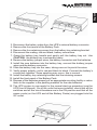
1
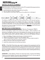
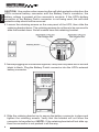
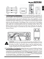
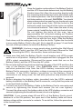
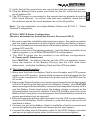
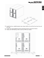
BATTERY PACK
User's Manual
English
TABLE OF CONTENTS
MINUTEMAN BATTERY PACK'S
USER'S MANUAL
1.
2.
Introduction
Installation
Installation Placement
Caster Removal
Installation Procedures
Style: 1 Plug and Play Configuration
Style: 2 Hardwire Configuration
Style: 3 Hardwire & Plug and Play Configuration
Style: 4 Pro Rackmount Configuration
Style: 5 Enterprise Universal Series Configuration
Style: 6 MCP-E Series Configuration
Style: 7 "Daisy Chained" Configuration
2
3
4
4
5
5
7
8
9
11
15
21
3.
Specifications
23
4.
Hot-Swappable Battery Replacement
Safety Precautions
Cautions
Service Policy
25
25
26
28
5.
Limited Product Warranty
29
© Copyright Para Systems, Inc., 2002
1
English
INTRODUCTION
Thank you for purchasing the MINUTEMAN external Battery Pack(s) for your
MINUTEMAN Uninterruptible Power Supply (UPS). It has been designed and
manufactured to provide many years of trouble free service.
The batteries used in the MINUTEMAN series products are sealed,
non-spillable, maintenance-free, lead-acid batteries, with the electrolyte
completely absorbed in the plates and separator material. For maximum
battery life, the Battery Pack(s) should be kept as cool as practical indoors.
Expected average battery life is 3 to 5 years. Replacement batteries and
additional Battery Packs are available from MINUTEMAN, or your local
distributor, and/or dealer.
When the batteries are replaced, dispose of the batteries according to local
regulations or return the batteries to your dealer or distributor for proper
disposal. If you cannot dispose of the old batteries, they may be returned to
MINUTEMAN for proper disposal. Call MINUTEMAN Technical Support for
instructions on returning the batteries.
IMPORTANT SAFETY INSTRUCTIONS
SAVE THESE INSTRUCTIONS !
This symbol indicates "ATTENTION"
This symbol indicates "RISK OF ELECTRICAL SHOCK"
Please read this manual before installing your Battery Pack(s), as it provides
the information to correctly set up your system for maximum safety and
performance. If you experience a problem with the Battery Pack(s), please refer
to the Troubleshooting Guide in the UPS User's Manual to correct the problem
or collect enough information so the MINUTEMAN Technical Support
Department can assist you. If factory service or Technical Support is required,
you can contact the MINUTEMAN Technical Support Department by phone
(1-972-446-7363) or by fax (1-972-446-9011) or visit our web site at
www.minutemanups.com (see Support & Service or Discussion Board).
2
voltages. DO NOT attempt to disassemble the unit. These Battery
Packs contain no user serviceable parts. Repairs and battery
replacement must be performed by AUTHORIZED SERVICE
PERSONNEL ONLY.
RECEIVING INSPECTION
Upon receipt of the Battery Pack(s), check the outer packing for any external
damage that may have been caused by the carrier. After removing the
MINUTEMAN Battery Pack from its carton, inspect the Battery Pack again for
any damages that may have occurred in shipping. If any damage is found,
notify the carrier and the place of purchase immediately. Warranty claims for
damage caused by the carrier will not be honored.
CAUTION: Never install a damaged piece of equipment.
PLEASE SAVE THE PACKING MATERIAL
The packing material in which the Battery Packs are shipped was carefully
designed to minimize any shipping damage. In the unlikely event that the
Battery Pack(s) needs to be returned to MINUTEMAN, please use the original
packing material. Since MINUTEMAN is not responsible for the shipping
damage incurred when the system is returned, the original packing material is
inexpensive insurance.
INSTALLATION
It is recommended that you turn the UPS off and disconnect it from the AC
outlet prior to connecting or disconnecting the battery terminals. If the Battery
Pack(s) must be changed while the UPS is supplying power to the protected
equipment, the Battery Pack(s) can ONLY be changed while the AC LINE
is supplying output power. DO NOT attempt to replace the batteries or the
Battery Pack(s) while the UPS is in the battery backup mode. Be extremely
careful while plugging or unplugging additional Battery Pack(s). Insure that the
battery cable connectors have the proper polarity alignment before plugging
them together. Improper alignment of the battery cable connector may result in
a short circuit that can destroy the Battery Pack(s) and the UPS, as well as
cause a fire and personal injury.
3
English
WARNING: These Battery Packs contain potentially hazardous
English
INSTALLATION PLACEMENT
Select the location of the Battery Pack(s) and the UPS using the following precautions:
1. Avoid locations near heating devices.
2. Avoid locations near water or excessive humidity.
3. Do not expose to direct sunlight.
4. Route power cords where they cannot be walked on or damaged.
The Battery Pack(s) and the UPS must be placed on a level smooth surface.
The Battery Packs cannot be stacked more than 4 units high. The Battery
Packs that weigh 80 lbs or more cannot be stacked more than 2 units high.
Install the UPS either on the side of the Battery Pack(s) with enough spacing
for proper air flow or on top of the Battery Pack(s). DO NOT install the Battery
Pack(s) on top of the UPS.
BATTERY PACK CASTER REMOVAL
(Must be performed by Authorized Service Personnel ONLY)
Some of the Battery Packs have casters for mobility. When mobility is not
desired or the Battery Packs are to be stacked, the casters can be removed
and replaced with rubber feet (provided). Follow the instructions below to
remove the casters and install the rubber feet on the XRT Battery Pack(s):
1. Move the Battery Pack(s) into the area of its final location.
2. Remove the Battery Pack(s) from the wooden skid.
3. With the appropriate support, raise the Battery Pack(s) high enough to
gain access to the bolts securing the casters.
4. Remove the four bolts securing the casters.
5. Install the rubber feet into the holes provided.
NOTE: A Qualified Technician may need to measure the equipment and the
installation site prior to the installation. Each installation should be planned and
reviewed before installing this heavy equipment into its final location. Verify that
the floor strength is sufficient enough to handle this extremely heavy equipment
prior to the actual installation. Use extreme caution when handling these heavy
Battery Packs.
WARNING! These Battery Packs are extremely heavy. Anytime the Battery
Pack(s) must be handled, be sure to use adequate personnel, strong supports
and equipment to safely handle the Battery Pack(s).
4
MINUTEMAN Battery Packs are available in several different configurations.
Some of the Battery Packs are designed for quick connections and others are
designed for hardwiring by Authorized Service Personnel Only. Follow the
correct procedure for the configuration style that you are installing. Use the
appropriate CAUTIONS for the model being installed. If you are unsure of the
configuration style that you have or have a question about the procedure, please
contact the MINUTEMAN Technical Support Department.
STYLE 1: Plug and Play Configuration
STYLE 2: Hardwire Configuration
STYLE 3: Hardwire & Plug and Play Configuration
STYLE 4: PRO Rackmount Configuration
STYLE 5: Enterprise Universal Series Configuration
STYLE 6: MCP-E Series Configuration
STYLE 7: "Daisy Chained" Configuration
STYLE 1: Plug and Play Configuration
(Must be performed by Authorized Service Personnel ONLY)
1. Be sure to read the installation placement procedure, caster removal
procedure, the cautions section and the safety precautions section before
installing the Battery Pack(s).
2. Make sure the UPS's power switch is turned off. If the Battery Pack(s) has
a circuit breaker, be sure that the circuit breaker is turned off.
3. Remove the self-stick protective strip (not required on all units) from the rear
of the UPS and from the Battery Pack's connector.
NOTE: The red connector is the battery positive (+) and the black connector is
the battery negative (-) on all MINUTEMAN Plug and Play configurations.
5
English
INSTALLATION PROCEDURES
English
CAUTION: Use caution when removing the self-stick protective strip from the
UPS's external battery connector and the Battery Pack's connector; the
battery voltage is present at the connector's contacts. If the UPS's battery
connector or the Battery Pack's connector is not being used, the self-stick
protective strip should not be removed.
4. Loosen the retaining screws on the rear panel of the UPS, then slide the
retaining bracket down. The retaining screws do not have to be removed to
slide the bracket down. Not all models have this retaining bracket.
5. Before plugging the connectors together, verify that they mate red to red and
black to black. Plug the Battery Pack's connector into the UPS's external
battery connector.
6. Slide the retaining bracket up to secure the battery connector in place and
tighten the retaining screws. Verify that the bracket will not allow the
connector to be pulled out. NOTE: If the retaining bracket will not slide up,
then the connector is not pushed in all the way.
6
Note: For the installation of multiple Battery Packs see STYLE 7: "Daisy
Chained" Configuration.
STYLE 2: Hardwire Configuration
(Must be performed by Authorized Service Personnel ONLY)
1. Be sure to read the installation placement procedure, caster removal
procedure, the cautions section and the safety precautions section before
installing the Battery Pack(s).
2. Make sure the UPS's power switch is turned off. If the Battery Pack(s) has a
circuit breaker, be sure that the circuit breaker is turned off.
3. Locate the terminal block on the back of the UPS. To properly identify, the
positive connection and the negative connection of the terminal block, refer
to the Installation Section in the UPS's User's Manual.
4. To locate the terminal block on the Battery Pack(s): The terminal block, on
some models of Battery Packs, has an access panel on the rear panel of the
Battery Pack. If the Battery Pack(s) has no access panel, the terminal block
is on the inside of the Battery Pack(s); the top cover will have to be removed.
WARNING: Use extreme CAUTION when the cover of the Battery Pack
is removed. There is a danger of Electrical Shock from the batteries.
7
English
7. The UPS system is now ready for the normal start-up procedure (see the
UPS User's Manual). On all the units that were installed, check that all the
switches and all the circuit breakers are in the ON position.
English
5. Connect a # 8 gauge wire from the UPS's positive (+) terminal to the Battery
Pack's positive (+) terminal. Connect a # 8 gauge wire from the UPS's
negative (-) terminal to the Battery Pack's negative terminal. Verify that the
polarity is correct. Not all of the Battery Packs come with connecting wires.
The minimum wire size for these hardwire connections is a # 8 gauge wire.
A safety earth ground wire may be attached from the UPS's chassis to the
Battery Pack's chassis, but it is not required.
6. Verify that all the connections are secure and that the polarity is correct.
7. Reinstall the cover and the cover plates, on the UPS and the Battery Pack(s).
Be sure that all the cover and cover plate screws are installed.
8. The UPS system is now ready for the normal start-up procedure (see the
UPS User's Manual). On all the units that were installed, check that all the
switches and all the circuit breakers are in the ON position.
Note: For the installation of multiple Battery Packs see STYLE 7: "Daisy
Chained" Configuration.
STYLE 3: Hardwire & Plug and Play Configuration
(Must be performed by Authorized Service Personnel ONLY)
1. Be sure to read the installation placement procedure, caster removal
procedure, the cautions section and the safety precautions section before
installing the Battery Pack(s).
2. Make sure the UPS's power switch is turned off. If the Battery Pack(s) has a
circuit breaker, be sure that the circuit breaker is turned off.
3. Locate the terminal block or the Plug and Play connector on the back of the
UPS. To properly identify the positive connection and the negative
connection of the terminal block or the Plug and Play connector, refer to the
Installation Section in the UPS User's Manual.
4. To locate the terminal block or the Plug and Play connector on the Battery
Pack(s): The terminal block on some models of Battery Packs has an
access panel on the rear panel of the Battery Pack. If the Battery Pack(s)
has no access panel, the terminal block is on the inside of the Battery
Pack(s); the top cover will have to be removed. The Plug and Play connector
cable comes out of the back panel of the Battery Pack. There is a self-stick
protective strip over the contacts of the connector.
NOTE: The red connector is the battery positive (+) and the black connector is
the battery negative (-) on all MINUTEMAN Plug & Play configurations.
WARNING: Use extreme CAUTION when the cover of the Battery
Pack is removed. There is a danger of Electrical Shock from the
batteries.
8
The UPS and the Battery Pack models determine the configuration style. The
drawing below reflects the Plug & Play configuration on the Battery Pack and
a Hardwire configuration on the UPS.
6. Verify that all the connections are secure and that the polarity is correct.
7. Reinstall the cover and the cover plates on the UPS and the Battery Pack(s).
Be sure that all the cover and cover plate screws are installed.
8. The UPS system is now ready for the normal start-up procedure (see the
UPS User's Manual). On all the units that were installed, check that all the
switches and all the circuit breakers are in the ON position.
Note: For the installation of multiple Battery Packs see STYLE 7: "Daisy
Chained" Configuration.
STYLE 4: PRO Rackmount Configuration
(Must be performed by Authorized Service Personnel ONLY)
1. Be sure to read the installation placement procedure, the cautions section
and the safety precautions section before installing the Battery Pack(s).
2. The PRO Rackmount Battery Pack(s) comes with mounting brackets for a
standard 19" (46.5cm) rack. The mounting brackets can also be reversed to
fit a 23" (59.2cm) standard rack. The screws for mounting the Battery Pack
to the rack are not included (screw size varies with rack size).
9
English
5. With this style of configuration, the UPS and the Battery Pack can be
connected using either of the following configurations:
A. The Battery Pack with the Plug & Play configuration and the UPS with
the Hardwire configuration.
B. The Battery Pack with the Hardwire configuration and the UPS with the
Plug & Play configuration.
English
English
3. The Battery Pack(s) has two additional sets of mounting bracket screw holes,
this will allow for a different set back.
WARNING: Use two or more people when installing the Battery
Pack(s) and the UPS into the rack (see the UPS User's Manual for
rack mounting the UPS). Use caution; these units are extremely
heavy. Do not move the rack after the units have been installed.
The rack maybe unstable due to the weight distribution.
4. After mounting the Battery Pack(s) and the UPS into the rack, make sure
the UPS's power switch is turned off.
5. Remove the self-stick protective strip from the rear of the UPS and from the
Battery Pack's connector. Use Caution when removing the self-stick
protective strip from the UPS's external battery connector and the Battery
Pack's connector; the battery voltage is present at the connector's contacts.
If the UPS's battery connector or the Battery Pack's connector is not being
used, the self-stick protective strip should not be removed.
6. Loosen the retaining screws on the rear panel of the UPS, then slide the
retaining bracket down. The retaining screws do not have to be removed to
slide the bracket down.
NOTE: The red connector is the battery positive (+) and the black connector
is the battery negative (-) on all MINUTEMAN Plug & Play configurations.
7. Before plugging the connectors together, verify that they mate red to red and
black to black. Plug the Battery Pack's connector into the UPS's external
battery connector.
10
1. Be sure to read the installation placement procedure, the cautions section
and the safety precautions section before installing the Battery Pack(s).
2. The Enterprise Universal Series Battery Packs have an internal charger in
each Battery Pack. The Battery Packs have a DIP switch on the rear panel
to set the input voltage for the chargers at either 115 VAC or 230 VAC.
WARNING! DAMAGE CAN OCCUR IF THE DIP SWITCH IS NOT SET FOR
THE CORRECT INPUT VOLTAGE. To change the input voltage setting:
unplug the Battery Pack's AC power cord, turn the DC circuit breaker off, set
the DIP switch to the desired voltage setting, turn the DC circuit breaker on
and plug the AC power cord into the AC outlet.
WARNING! DO NOT PLUG THE BATTERY PACK'S POWER CORD INTO
THE UPS's OUTPUT RECEPTACLES, DAMAGE TO THE BATTERY PACK'S
INTERNAL CHARGER MAY OCCUR.
3. The circuit breaker on the back panel turns the battery voltage ON and OFF.
To turn the charger OFF, unplug the Battery Pack's AC power cord from the
AC outlet. To turn the charger ON, plug the Battery Pack's AC power cord
into the AC outlet. NOTE: The AC power cord can be "Daisy Chained" up to
a maximum of ten Battery Packs (see "Daisy Chained" Configuration page 21).
4. On the Tower and Wall Mount Configurations, the face plate can be rotated to
read in the upright position. To do so, pull the front panel off the Battery Pack.
On the backside of the front panel, locate four tabs holding the face plate to
the front panel. Push the four tabs inward and the face plate will pop out.
Reinstall the face plate so that it reads in the upright position. Reinstall the
front panel on the Battery Pack.
5. The Enterprise Universal Series Battery Packs can be installed in
four different configurations: A. Desk Top, B. Tower, C. Rackmount,
D. Wall Mount.
A. The Desk Top Configuration allows the user to install the monitor, the
UPS and the Battery Pack(s) in one single stack. There are four
self- stick rubber feet provided with the Battery Pack(s) and the UPS.
The four rubber feet can be installed on the bottom side of the Battery
Pack(s) and the UPS (see the UPS User's Manual for installation).
11
English
8. Slide the retaining bracket up to secure the battery connector in place and
tighten the retaining screws. Verify that the bracket will not allow the
connector to be pulled out. NOTE: If the retaining bracket will not slide up,
then the connector is not pushed in all the way.
9. Verify that all the connections are secure and that the polarity is correct.
10. The UPS system is now ready for the normal start-up procedure (see the
UPS User's Manual). On all the units that were installed, check that all the
switches and all the circuit breakers are in the ON position.
Note: For the installation of multiple Battery Packs see STYLE 7: "Daisy
Chained" Configuration.
STYLE 5: Enterprise Universal Series Configuration
(Must be performed by Authorized Service Personnel ONLY)
English
Use CAUTION: the Battery Pack(s) are extremely heavy. Once the
location of the Battery Pack(s) and the UPS have been determined, stand
the Battery Pack on its side. Attach the self-stick rubber feet to the bottom
of the Battery Pack, approximately 2" from each corner. Lay the Battery
Pack down on the four rubber feet. Stack the UPS and the monitor on top of
the Battery Pack(s) as shown below.
NOTE: Do not stack the Battery Pack(s) on top of the UPS or any other
equipment. Go to step #6 on page 14 and finish the rest of this procedure to
install the Battery Pack(s).
B. The Tower Configuration allows the user to install the Battery Pack(s)
and the UPS (see the UPS User’s Manual for installation) in the upright
position next to the tower computer. A tower bracket kit is available for both
the Battery Pack(s) and the UPS. Use CAUTION: the Battery Pack(s) and
the UPS are extremely heavy. Once the location of the Battery Pack(s) and
the UPS have been determined, lay the Battery Pack down flat on a desk or
table. Then position the UPS on top of the Battery Pack so that the front
panels are facing in the same direction and the face plates are on the same
end of the units. Position the units so the tower feet brackets will slide on the
units. Locate the mounting screw holes on the side panels of the units. On
each unit there are four mounting screw holes at the front of the unit and four
mounting screw holes at the rear of the unit. Align the tower feet brackets
with the mounting screw holes and attach with the retaining screws. Align
the middle locking brackets with the mounting screw holes and attach with
the retaining screws. This will lock the Battery Pack and the UPS
together. Stand the Battery Pack and the UPS up on the tower feet
brackets. Slide the Battery Pack, the UPS and the tower computer together.
Note: Verify that the Battery Pack and the UPS are stable. The face plates
can be rotated to read in the upright position. To do so, pull the front panels
off the Battery Pack(s) and the UPS. On the backside of the front panel,
locate four tabs holding the face plate to the front panel. Push the four tabs
inward and the face plate will pop out. Position the face plate so that it reads
in the upright position. Reinstall the front panels on the Battery Pack(s) and
the UPS. Go to step #6 on page 14 and finish the rest of this procedure to
install the Battery Pack(s).
12
English
C. The Rackmount Configuration has mounting brackets for a standard 19"
(46.5cm) rack. Mounting brackets to fit a 23" (59.2cm) standard rack are
also available. The screws for mounting the Battery Pack(s) to the rack are
not included (screw size varies with rack size). The installation of the
mounting brackets, is as follows: The Rackmount kit includes two mounting
brackets and eight retaining screws. Locate the mounting bracket screw
holes on the side panels of the Battery Pack, at the front of the Battery
Pack. Align the mounting bracket with the mounting bracket screw holes
and attach the mounting bracket with the retaining screws. Mount the
Battery Pack(s) and the UPS (see the UPS User's Manual) into the rack.
Go to step #6 on page 14 and finish the rest of this procedure to install the
Battery Pack(s).
WARNING: Use two or more people when installing the Battery Pack(s)
and the UPS into the rack (see the UPS User's Manual for rack
mounting the UPS). Use caution; these units are extremely heavy.
Do not move the rack after the units have been installed. The rack
maybe unstable due to the weight distribution.
D. The Wall Mount Configuration allows the user to mount the Battery Pack(s)
and the UPS (see the UPS User's Manual for installation) on the wall. A wall
mount bracket kit available for both the Battery Pack(s) and the UPS. The kit
includes two mounting brackets, twelve retaining screws, four bolts, one drill
bit and the template for the bolt holes. Use CAUTION: the Battery Pack(s)
are extremely heavy. The Battery Pack's side panels have mounting bracket
screw holes for attaching the wall mounting brackets.
13
English
Once the location and position of the Battery Pack(s)
and the UPS have been determined, lay the Battery
Pack(s) down flat. Align the mounting bracket with
the mounting bracket screw holes and attach with
the retaining screws. Use the template to mark the
bolt hole position on the wall. CAUTION: You should
always were protective gear for your hands and eyes
when operating power tools. Drill the holes for the
bolts and make sure that all of the holes are drilled
into structural material. Then clean the area of any
loose material. Install the four bolts into the bolt holes.
Do not tighten the bolts all the way, leave
approximately 3/8" of the bolt sticking out. Position
the Battery Pack so that the mounting bracket keyed
holes line up with the four bolts. Slide the Battery
Pack down until its resting securely on the four bolts. Tighten the four bolts
to secure the Battery Pack to the wall. Go to step #6 on page 14 and finish
the rest of this procedure to install the Battery Pack(s).
WARNING: Use two or more people when installing the Wall Mount
Battery Pack(s) and the UPS (see the UPS User's Manual for Wall
Mounting the UPS). Use caution; these units are heavy.
6. Make sure that both the Battery Pack's circuit breaker and UPS's power
switch are in off position. Unplug all the equipment that is plugged into the
UPS's output receptacles. Disconnect the power cords that are on the
Battery Pack(s) and the UPS from the AC outlet.
7. Remove the self-stick protective strip from the rear of the UPS and from the
rear of the Battery Pack(s). Use CAUTION when removing the
self-stick protective strip from the UPS's battery connector and the
Battery Pack's connector; the battery voltage is present at the connector's
contacts. If the UPS's battery connector or the Battery Pack's
connector is not being used, the self-stick protective strip should not be
removed.
8. Before plugging the battery cable (provided) into the UPS's external
battery connector or the Battery Pack's connector, verify that they mate red
to red and black to black.
9. Connect one end of the Battery Cable to the Battery Pack's connector and
secure by tightening the thumb bolt screws (do not over tighten).
10. Connect the other end of the battery cable to the UPS's battery connector and
secure by tightening the thumb bolt screws (do not over tighten).
CAUTION: If you reverse steps #9 and #10 or if the Battery Pack's circuit
breaker is in the ON position, the open end of the battery cable will have
battery voltage at the connector's contacts. To avoid this, follow the procedure
in the correct order.
14
Note: For the installation of multiple Battery Packs see STYLE 7: "Daisy
Chained" Configuration.
STYLE 6: MCP-E Series Configuration
(Must be performed by Authorized Service Personnel ONLY)
1. Be sure to read the installation placement procedure, the cautions section
and the safety precautions section before installing the Battery Pack(s).
2. The circuit breaker on the back panel of the battery pack(s) turns the battery
voltage OFF and ON.
3. The red connector is the battery positive (+) and the black connector is the
battery negative (-) on all MINUTEMAN MCP-E configurations.
4. The MCP-E series can be installed in two different configurations:
A. Tower and B. Rackmount.
Use CAUTION: the Battery Pack(s) and the UPS are extremely heavy.
Once the location of the Battery Pack(s) and the UPS have been
determined, verify that the Battery Pack and the UPS are stable.
A. The Tower Configuration
1. Make sure that both the Battery Pack's circuit breaker and UPS's power
switch are in OFF position. Unplug all the equipment that is plugged into the
UPS's output receptacles. Disconnect the power cord on the UPS from the
AC outlet.
2. Remove the External battery connector's access panel from the back panel
of the UPS and from the back panel of the Battery Pack(s). Use CAUTION
when removing the External battery connector's access panel from the UPS's
and the Battery Pack's back panel; the battery voltage is present at the
External battery connector's contacts. If the UPS's battery connector or the
Battery Pack's connector is not being used, the External battery connector's
access panel should not be removed.
3. Before plugging the battery cable (provided) into the UPS's external battery
connector or the Battery Pack's connector, verify that they mate red to red
and black to black.
4. Connect one end of the Battery Cable to the Battery Pack's connector and
secure by tightening the strain relief screw (do not over tighten).
5. Connect the other end of the battery cable to the UPS's battery connector
and secure by tightening the strain relief screw (do not over tighten).
15
English
11. Verify that all the connections are secure and that the polarity is correct.
12. Plug the Battery Pack's power cord back into the AC outlet and turn the
circuit breaker ON.
13. The UPS system is now ready for the normal start-up procedure (see the
UPS User's Manual). On all the units that were installed, check that all
the switches and all the circuit breakers are in the ON position.
English
CAUTION: If you reverse steps #4 and #5 or if the Battery Pack's circuit
breaker is in the ON position, the open end of the battery cable will have
battery voltage at the connector's contacts. To avoid this, follow the
procedure in the correct order.
6. Verify that all the connections are secure and that the polarity is correct.
7. The UPS system is now ready for the normal start-up procedure (see the
UPS User's Manual). On all the units that were installed check that all the
switches and all the circuit breakers are in the ON position.
Installation of the mounting tray and the stabilizing feet.
The MCP BP5000 and the MCP BP7000 must be installed into a stationary
position due to the hardwiring of the input and the output of the UPS.
Use CAUTION: the Battery Pack(s) and the UPS are extremely heavy.
1. Move the UPS and the battery pack(s) into the desired location.
2. Lay the mounting trays on the floor next to the UPS and the battery pack(s)
as shown.
3. Attach the two mounting trays together.
4. Roll the UPS onto the mounting tray.
5. Roll the battery pack onto the mounting tray.
6. Align the four screw holes on the mounting tray with the four screw holes on
the bracket at the front and rear of the UPS.
7. Install the four mounting tray retaining screws.
8. Align the four screw holes on the mounting tray with the four screw holes on
the bracket at the front and rear of the UPS.
9. Install the four mounting tray retaining screws.
16
English
10. Install the four stabilizing feet as shown below, two at the front and two at
the rear.
11. Install the eight stabilizing feet retaining screws as shown below.
12. Verify that the Battery Pack and the UPS are stable.
17
English
13. Install the retaining bracket as shown below.
14. Loosen the two cover screws and slide the retaining bracket into place.
15. Retighten the two cover screws.
16. Make sure that, the UPS's and the Battery Pack's circuit breakers are in
OFF position.
17. Make sure that the UPS's power switch is in the OFF position.
18. Make sure that the input circuit breaker (at the breaker panel) is in the
OFF position.
19. Remove the External battery connector's access panel from the back panel
of the UPS and from the back panel of the Battery Pack(s). Use CAUTION
when removing the External battery connector's access panel from the
UPS's and the Battery Pack's back panel; the battery voltage is present at
the External battery connector's contacts. If the UPS's battery connector
or the Battery Pack's connector is not being used, the External battery
connector's access panel should not be removed.
20. Before plugging the battery cable (provided) into the UPS's external battery
connector or the Battery Pack's connector, verify that they mate red to red
and black to black.
21. Connect one end of the Battery Cable to the Battery Pack's connector and
secure by tightening the strain relief screw (do not over tighten).
18
B. The Rackmount Configuration has mounting brackets for a standard 19"
(46.5cm) rack. Mounting brackets to fit a 23" (59.2cm) standard rack are
also available. The screws for mounting the Battery Pack(s) to the rack are
not included (screw size varies with rack size). The installation of the mounting
brackets is as follows:
Locate the mounting bracket screw holes on the side panels of the Battery
Pack, at the front of the Battery Pack. Align the mounting bracket with the
mounting bracket screw holes and attach the mounting bracket with the
retaining screws. Mount the Battery Pack(s) and the UPS (see the UPS
User's Manual) into the rack.
19
English
22. Connect the other end of the battery cable to the UPS's battery connector
and secure by tightening the strain relief screw (do not over tighten).
CAUTION: If you reverse steps #21 and #22 or if the Battery Pack's circuit
breaker is in the ON position, the open end of the battery cable will have
battery voltage at the connector's contacts. To avoid this, follow the
procedure in the correct order.
23. Verify that all the connections are secure and that the polarity is correct.
24. The UPS system is now ready for the normal start-up procedure (see the
UPS User's Manual). On all the units that were installed, check that all the
switches and all the circuit breakers are in the ON position.
English
WARNING: Use two or more people when installing the Battery Pack(s)
and the UPS into the rack (see the UPS User's Manual for rack
mounting the UPS). Use caution; these units are extremely heavy. Do
not move the rack after the units have been installed. The rack may be
unstable due to the weight distribution.
1. Make sure that the circuit breakers on both the UPS and the Battery Pack(s)
are in OFF position.
2. Make sure that the UPS's power switch is in the OFF position.
3. Make sure that the input circuit breaker (at the wall breaker box) is in the
OFF position.
4. Remove the External battery connector's access panel from the back panel
of the UPS and from the back panel of the Battery Pack(s). Use CAUTION
when removing the External battery connector's access panel from the
UPS's and the Battery Pack's back panel; the battery voltage is present
at the External battery connector's contacts. If the UPS's battery connector
or the Battery Pack's connector is not being used, the External battery
connector's access panel should not be removed.
5. Before plugging the battery cable (provided) into the UPS's external battery
connector or the Battery Pack's connector, verify that they mate red to red
and black to black.
6. Connect one end of the Battery Cable to the Battery Pack's connector and
secure by tightening the strain relief screw (do not over tighten).
7. Connect the other end of the battery cable to the UPS's battery connector
and secure by tightening the strain relief screw (do not over tighten).
CAUTION: If you reverse steps #6 and #7 or if the Battery Pack's circuit
breaker is in the ON position, the open end of the battery cable will have
battery voltage at the connector's contacts. To avoid this, follow the
procedure in the correct order.
8. Verify that all the connections are secure and that the polarity is correct.
9. The UPS system is now ready for the normal start-up procedure (see the
UPS User's Manual). On all the units that were installed, check that all the
switches and all the circuit breakers are in the ON position.
Note: For the installation of multiple Battery Packs see STYLE 7: "Daisy
Chained" Configuration.
20
"Daisy Chained" means hooking one Battery Pack to another Battery Pack
to another Battery Pack; this chain could go on indefinitely. Follow the steps
below to Daisy Chain the Battery Packs.
1. Be sure to read the installation placement procedure, the cautions section,
the safety precautions section and the Configuration Style for your Battery
Pack before Daisy Chaining the Battery Pack(s).
2. Make sure that all the Battery Pack's circuit breakers and UPS's power
switch, are in OFF position. Unplug all the equipment that is plugged into the
UPS's output receptacles. Disconnect the power cords that are on the
Battery Packs and the UPS from the AC outlet.
3. Remove the self-stick protective strip from the rear of the UPS and from the
rear of the Battery Packs. Use CAUTION when removing the self-stick
protective strip from the UPS's battery connector and the Battery Pack's
connector; the battery voltage is present at the connector's contacts. If the
UPS's battery connector or the Battery Pack's connector is not being used,
the self-stick protective strip should not be removed.
4. Before plugging the battery cable (provided) into the UPS's external battery
connector/terminal block or the Battery Pack's connector/terminal block, verify
that they mate red (positive) to red (positive) and black (negative) to black
(negative).
5. Connect one end of the Battery Cable to the Battery Pack's connector/
terminal block and secure by tightening the screws (do not over tighten).
6. Connect the other end of the battery cable to the UPS's battery connector/
terminal block and secure by tightening the screws (do not over tighten).
CAUTION: If you reverse steps #5 and #6 or if the Battery Pack's circuit
breaker is in the ON position, the open end of the battery cable will have
battery voltage at the connector's contacts. To avoid this, follow the
procedure in the correct order.
7. Connect the next battery cable to the first Battery Pack's unused battery
connector/terminal block and secure by tightening the screws (do not
overtighten).
8. Connect the other end of the battery cable to the next Battery Pack's battery
connector/terminal block and secure by tightening the screws (do not
over tighten).
9. Connect the next battery cable to the last Battery Pack's unused battery
connector/terminal block and secure by tightening the screws (do not
overtighten).
10. Connect the other end of the battery cable to the next Battery Pack's
battery connector/terminal block and secure by tightening the screws (do
not over tighten).
21
English
STYLE 7: "Daisy Chained" Configuration
(Must be performed by Authorized Service Personnel ONLY)
English
11. After the installation of all the Battery Packs is complete, verify that all the
connections are secure and that the polarity is correct. Verify that all
covers, access panels, retaining brackets and their screws are installed.
12. The UPS system is now ready for the normal start-up procedure (see the
UPS User's Manual). On all the units that were installed, check that all the
switches and all the circuit breakers are in the ON position and that all the
power cords (on the UPS and all the Battery Packs) are plugged into the
AC outlet.
CAUTION: Be careful not to let the open end of the battery cable or wires
short to any exposed metal; the Battery Voltage is at the connector's
contacts or wire's terminals.
22
English
SPECIFICATIONS
!
BATTERY PACK
MODEL #
BPX48V17
BP120V13
BP144V13
BP192V17
BP24V10
BP24V20
BP24V34A
BP48V10
BP48V13
BP48V17
BP48V34
BP60V17A
CP3BP1
CP6BP1
CP6BP4
CPR3BP3
EBP1
EBP2
EBP3
EBP4
EBP3000LT
MCPBP1
MCPBP2
MCPBP3
MCP BP1000
MCP BP2000
MCP BP3000
MCP BP5000
MCP BP7000
MCP BP1000RM
MCP BP2000RM
MCP BP3000RM
PROBPr1
XRTBP1
XRTBP3
BATTERY
TYPE
12V18AH
12V7.2AH
12V7.2AH
12V18AH
6V10AH
6V10AH
12V18AH
6V10AH
12V7.2AH
12V18AH
12V18AH
12V18AH
12V7.2AH
12V25AH
12V7.2AH
12V7.2AH
12V7.2AH
12V12AH
12V7.2AH
12V12AH
12V12AH
12V25AH
12V7.2AH
12V7.2AH
12V7.2AH
12V7.2AH
12V7.2AH
12V7.2AH
12V7.2AH
12V7.2AH
12V7.2AH
12V7.2AH
12V18AH
12V18AH
12V90AH
BATTERY
QUANTITY
4
20
24
16
4
8
4
8
8
4
8
5
20
20
20
20
4
4
8
8
8
20
12
16
6
18
24
40
48
6
12
16
4
4
4
BATTERY
PART #
37000006
37000007
37000007
37000006
37000008
37000008
37000006
37000008
37000007
37000006
37000006
37000006
37000007
37000018
37000007
37000007
37000007
37000009
37000002
37000009
37000009
37000018
37000007
37000007
37000007
37000007
37000007
37000007
37000007
37000007
37000007
37000007
37000006
37000006
37000019
23
English
BATTERY PACK
MODEL #
CK1-2030X-240
CK1-2035X-240
CK1-2050XL-240
CK3-2065-240
CK3-2080X-240
CK3-2090X-240
CK3-20110X-240
CK3-20150X-240
CK4-4065-240
CK4-4080X-240
CK4-4090X-240
CK4-40100X-240
CK4-40110X-240
CK4-40120X-240
CK4-40150X-240
BATTERY
TYPE
12V30AH
12V35AH
12V50AH
12V65AH
12V80AH
12V90AH
12V110AH
12V150AH
12V65AH
12V80AH
12V90AH
12V100AH
12V110AH
12V120AH
12V150AH
BATTERY
QUANTITY
20
20
20
20
20
20
20
20
40
40
40
40
40
40
40
BATTERY
PART #
37000011
37000013
37000014
37000016
XXXXXXXX
37000019
XXXXXXXX
XXXXXXXX
37000016
XXXXXXXX
37000019
37000014
XXXXXXXX
XXXXXXXX
XXXXXXXX
XXXXXXXX - For current prices and availability on all the batteries, visit our Web
site at www.minutemanups.com or call the Technical Support Department
at 972-446-7363.
STORAGE INSTRUCTIONS
When the Battery Pack(s) is to be stored and not used for an extended period
of time, the Battery Pack(s) will need to be charged for 24 hours prior to
storage. The Battery Pack(s) should be kept in a cool, dry location. In
moderate climates, the Battery Pack(s) should be charged for 8 hours every 3
months. In high temperature locations, the Battery Pack(s) should be charged
for 8 hours every 2 months.
24
English
"
HOT-SWAPPABLE BATTERY REPLACEMENT
SAFETY PRECAUTIONS
Read this manual carefully before installing the Battery Pack(s) or replacing the
batteries. All instructions and warnings should be followed during the
installation, operation and the maintenance of the Battery Pack(s). Do not
attempt to disassemble the unit; there are no user serviceable parts.
(Repairs and battery replacement must be performed by Authorized
Service Personnel ONLY)
CAUTION! The battery(s) can present a risk of electrical shock
or burn from high short circuit current.
CAUTION! The batteries in these battery pack(s) are recyclable.
Dispose of the batteries properly. The batteries contain lead and pose
a hazard to the environment and human health if not disposed of
properly. Refer to local codes for proper disposal requirements or
return the batteries to Minuteman.
CAUTION! Do not open or mutilate batteries. Released
electrolyte is harmful to the skin, eyes and may be toxic.
CAUTION! Do not dispose of batteries in a fire. The batteries
may explode.
CAUTION! Avoid installing the battery pack(s) in a location
where there is water, excessive humidity, or direct sunlight.
CAUTION! Do not allow any foreign objects to get inside of the
battery pack(s). Do not put objects containing liquids on or near the
battery pack(s)
25
English
CAUTIONS
When replacing the batteries in the Battery Pack(s), the following precautions
should be followed:
1. Turn off the equipment plugged into the UPS, then turn off the UPS.
2. Before removing the cover screws, disconnect the equipment from the output
receptacles, the power cord from the AC outlet and the battery connectors
from the UPS.
3. Remove watches, rings and any other metallic jewelry before servicing the
Battery Pack(s) or the UPS.
4. Use tools with insulated handles.
5. Wear rubber gloves, boots and protective goggles.
6. Do not lay tools or any other objects on top of the batteries.
7. Do not short the battery terminals together or to the case.
8. Disconnect charging source prior to connecting or disconnecting battery
terminals.
9. Determine if the battery is inadvertently grounded. If inadvertently grounded,
remove source of the ground. Contact with any part of a grounded battery
can result in electrical shock. The likelihood of such shock will be reduced if
such grounds are removed during installation and maintenance.
10. It is recommended that you draw a sketch of the batteries and the battery
connections before you remove the old batteries.
11. Verify the correct placement and the connections of the new batteries.
12. Verify that the battery brackets and the mechanical fittings are installed
correctly.
PLEASE READ THE CAUTIONS AND SAFETY PRECAUTIONS BEFORE
ATTEMPTING TO REPLACE THE BATTERIES
Hot-swappable batteries means that the batteries can be replaced without
powering down the whole UPS system. NOTE: If there is a power
interruption, while replacing the batteries, the runtime will be less than
expected. (Must be performed by Authorized Service Personnel ONLY)
1. Turn the DC circuit breaker on the rear panel of the Battery Pack(s) off.
2. Unplug the AC power cord on the Battery Pack(s) from the AC outlet.
26
English
3. Disconnect the battery cable from the UPS's external battery connector.
4. Remove the front panel of the Battery Pack.
5. Remove the four retaining screws from the battery tray retaining bracket.
6. Disconnect the mating, red and black, battery connectors.
7. Grasp the battery tray handle and gently pull the battery tray out. Use
CAUTION: the battery tray is extremely heavy.
8. Remove the battery jumper wires, the battery connector and the batteries.
9. Install the new batteries into the battery tray, connect the battery jumper
wires and the battery connector.
10. Slide the battery tray into the case, taking care not to pinch the wires.
11. Verify proper polarity, red to red and black to black. Connect the battery's
connectors together. Some sparking may occur; this is normal.
12. Install the battery tray retaining bracket and the retaining screws.
13. Install the front panel of the Battery Pack.
14. Dispose of the batteries properly at an appropriate recycling facility or return
them to the supplier in the packing material for the new batteries.
15. The UPS system is now ready for the normal start-up procedure (see the
UPS User's Manual). On all the units that were installed, check that all the
switches and all the circuit breakers are in the ON position and that all the
power cords (on the UPS and all the Battery Packs) are plugged into the
AC outlet.
27
English
SERVICE POLICY
1. Use the Troubleshooting Guide in the UPS User's Manual to eliminate
obvious causes.
2. Verify there are no circuit breakers tripped and that the Battery Pack's power
cord (not on all models) is plugged into the AC outlet. A tripped circuit breaker
is the most common problem.
3. If you are not getting the expected runtime, charge the Battery Pack(s) for 8
hours then retest.
4. Call your dealer for assistance. If you cannot reach your dealer, or if they
cannot resolve the problem. Call or fax MINUTEMAN Technical Support at
the following numbers: Voice phone (972) 446-7363, Fax line (972) 446-9011
or visit our web site at www.minutemanups.com, the "Discussion Board".
Please have the following information available BEFORE calling the
Technical Support Department.
A. Your Name and address.
B. Where and when the Battery Pack was purchased.
C. All of the model information on the rear panel of your Battery Pack.
D. Any information on the failure.
E. A description of the protected equipment, including model numbers if
possible.
F. A technician will ask you for this information and, if possible, help solve
your problem over the phone. In the event that the unit requires factory
service, the technician will issue you a Return Material Authorization
Number (RMA #).
G. If the Battery Pack(s) is under warranty, the repairs will be done at no
charge. If not, there will be a charge for repair.
5. Pack the Battery Pack(s) in its original packaging. If the original packaging
is no longer available, ask the Technical Support technician about obtaining
a new set. It is important to pack the Battery Pack(s) properly in order to
avoid damage in transit. Never use Styrofoam beads for a packing material.
Include a letter with your name, address, day time phone number, RMA
number, a copy of your original sales receipt, and a brief description of the
problem.
6. Mark the RMA # on the outside of all packages. The factory cannot accept
any package without the RMA # marked on the outside.
7. Return the Battery Pack(s) by insured, prepaid carrier to:
MINUTEMAN
Para Systems Inc.
1455 LeMay Drive
Carrollton, Tx. 75007
28
English
#
LIMITED PRODUCT WARRANTY
Para Systems Inc. (Para Systems) warrants this equipment, when properly
applied and operated within specified conditions, against faulty materials or
workmanship for a period of three years from the date of original purchase by the
end user. For equipment sites within the United States and Canada, this warranty
covers repair or replacement of defective equipment at the discretion of Para
Systems. Repair will be from the nearest authorized service center. Replacement
parts and warranty labor will be borne by Para Systems. For equipment located
outside of the United States and Canada, Para Systems only covers faulty parts.
Para Systems products repaired or replaced pursuant to this warranty shall be
warranted for the unexpired portion of the warranty applying to the original product.
This warranty applies only to the original purchaser who must have properly
registered the product within 10 days of purchase.
The warranty shall be void if (a) the equipment is damaged by the customer, is
improperly used, is subjected to an adverse operating environment, or is operated
outside the limits of its electrical specifications; (b) the equipment is repaired or
modified by anyone other than Para Systems or Para Systems-approved personnel;
or (c) has been used in a manner contrary to the product’s operating manual or other
written instructions.
Any technical advice furnished before or after delivery in regard to use or
application of Para Systems’s equipment is furnished without charge and on the
basis that it represents Para Systems’s best judgment under the circumstances,
but it is used at the recipient’s sole risk.
EXCEPT AS PROVIDED HEREIN, PARA SYSTEMS MAKES NO WARRANTIES,
EXPRESSED OR IMPLIED, INCLUDING WARRANTIES OF MERCHANTABILITY AND
FITNESS FOR A PARTICULAR PURPOSE. Some states do not permit limitation of
implied warranties; therefore, the aforesaid limitation(s) may not apply to the
purchaser.
EXCEPT AS PROVIDED ABOVE, IN NO EVENT WILL PARA SYSTEMS BE
LIABLE FOR DIRECT, INDIRECT, SPECIAL, INCIDENTAL, OR CONSEQUENTIAL
DAMAGES ARISING OUT OF THE USE OF THIS PRODUCT, EVEN IF ADVISED OF
THE POSSIBILITY OF SUCH DAMAGE. Specifically, Para Systems is not liable for
any costs, such as lost profits or revenue, loss of equipment, loss of use of
equipment, loss of software, loss of data, cost of substitutes, claims by third parties,
or otherwise. The sole and exclusive remedy for breach of any warranty, expressed
or implied, concerning Para Systems’s products and the only obligation of Para
Systems hereunder, shall be the repair or replacement of defective equipment,
components, or parts; or, at Para Systems’s option, refund of the purchase price or
substitution with an equivalent replacement product. This warranty gives you
specific legal rights and you may also have other rights which vary from state to state.
Longer term and F.O.B. job site warranties are available at extra cost. Contact
Para Systems (1-972-446-7363) for details.
29
Para Systems, Inc.
1455 LeMay Dr.
Carrollton, TX 75007
Phone: (972) 446-7363
Fax: (972) 446-9011
QuickFax Info System: 1-800-263-3933
Internet: www.minutemanups.com
P/N 34000011-Rev. 2