1
Application Note: Zynq-7000 AP SoC
Boost Software Performance on Zynq-7000
AP SoC with NEON
XAPP1206 v1.1 June 12, 2014
Author: Haoliang Qin
Summary
Xilinx® Zynq®-7000 All Programmable SoC is an architecture that integrates a dual-core ARM®
Cortex™-A9 processor, which is widely used in embedded products. Both ARM Cortex-A9
cores have an advanced single instruction, multiple data (SIMD) engine, also known as NEON.
It is specialized for parallel data computation on large data sets. This document explains how to
use NEON to improve software performance and cache efficiency, thus improving NEON
performance generally.
Introduction
Generally speaking, a CPU executes instructions and processes data one-by-one. Typically,
high performance is achieved using high clock frequencies, but semiconductor technology
imposes limits on this. Parallel computation is the next strategy typically employed to improve
CPU data processing capability. The SIMD technique allows multiple data to be processed in
one or just a few CPU cycles. NEON is the SIMD implementation in ARM v7A processors.
Effective use of NEON can produce significant software performance improvements.
Document Content Overview
Technical information provided in the this document includes:
Before You Begin: Important Concepts
This document provides the following information you need to be more effective when
optimizing your code:
•
Software Optimization Basics
•
NEON Basics
Software Performance Optimization Methods
This document describes four ways to optimize software performance with NEON :
•
Using Using NEON Optimized Libraries
As Cortex-A9 prevails in embedded designs, many software libraries are optimized for
NEON and have performance improvements. This document lists those libraries which are
frequently used by the community.
•
Using Compiler Automatic Vectorization
GCC, the popular open source compiler, can generate NEON instructions with proper
compilation options. However, the C language does not excel at expressing parallel
computations. You might need to modify your C code to add compiler hints. Lab 1 provides
a hands-on example.
•
Using NEON Intrinsics
Usually, the compiler handles simple optimizations well (optimizations such as register
allocation, instruction scheduling, etc.). However, you might need to use NEON intrinsics
when the compiler fails to analyze and optimize more complex algorithms. Moreover, some
NEON instructions have no equivalent C expressions, and intrinsics or assembly are the
© Copyright 2014 Xilinx, Inc. Xilinx, the Xilinx logo, Artix, ISE, Kintex, Spartan, Virtex, Vivado, Zynq, and other designated brands included herein are trademarks of Xilinx in the
United States and other countries. AMBA, AMBA Designer, ARM, ARM1176JZ-S, CoreSight, Cortex, and PrimeCell are trademarks of ARM in the EU and other countries. All
other trademarks are the property of their respective owners.
XAPP1206 v1.1 June 12, 2014
www.xilinx.com
1
Software Examples and Labs
only options. So, in some situations, you might need to re-write time-critical code in NEON
intrinsics to achieve better performance. Lab 2 provides a hands-on example.
•
Optimizing NEON Assembler Code
In some situations, the compiler might be unable to generate the highest performance
binary. When this happens, you must write functions in NEON assembler code, with
everything under developer control. Lab 3 provides a hands-on example.
Boost NEON Performance by Improving Memory Access Efficiency
When discussing NEON performance, there is usually an underlying assumption that the
memory subsystem can follow the pace of the CPU. In practice, this means that all data and
instructions are using L1 cache. This cannot always be true, however, especially when a data
set is very large. This application note discusses three techniques for improving cache
efficiency:
•
Loading and Storing Multiple Data in a Burst
•
Using the Preload Engine to Improve the Cache Hit Rate
•
Using Tiles to Prevent Cache Thrashing
These techniques can benefit not only NEON code, but software code generally.
Prerequisites
This application note assumes that you know how to use Xilinx SDK (Software Development
Kit) to create a new project, import source files, debug, and run standalone applications on
hardware.
Software
Examples and
Labs
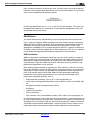
Software examples and labs are available for this application note. You can download a ZIP file
containing these from the following location:
https://secure.xilinx.com/webreg/clickthrough.do?cid=359072.
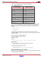
The design matrix is shown in Table 1.
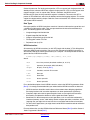
Table 1: Design Matrix
Parameters
Description
General
Targeted devices
All Zynq-7000 devices
Source code provided
Yes
Source code format
C and assembler
Uses code/IP from existing Xilinx application note
reference designs, CORE™ Generator software, or
third-party
No
Verification
XAPP1206 v1.1 June 12, 2014
Verified on hardware
Yes
Software development tools
SDK 2013.4
Hardware platform used for verification
ZC702 evaluation kit
www.xilinx.com
2
Before You Begin: Important Concepts
Before You
Begin:
Important
Concepts
Before addressing specific optimization techniques, it is important to understand some related
concepts. The sections below describe:
•
Software Optimization Basics
•
NEON Basics
Software Optimization Basics
In an embedded system, you often optimize for speed, but you can also optimize for battery life,
code density, or memory footprint. Generally speaking, embedded systems use highly
customized hardware and software systems for specific purposes. Most of time you need to
trade off between code density, speed, debug visibility, and other factors. This application note
explains how to increase software speed. This has the additional benefit of improving
performance and can be crucial to lowering power consumption and conserving battery life. If
a task finishes in fewer cycles, you can turn off the power for longer periods.
There are several methods for optimizing software to boost performance. You can, for example:
•
Change the algorithm computation order to avoid cache thrashing and improve cache
efficiency. Usually you must do this for computation on matrices. This application note
provides an example of this.
•
Develop the algorithm to use the underlying processor architecture more efficiently,
including but not limited to instructions. This application note focuses on how an
understanding of CPU hardware can help to optimize code. This kind of knowledge leads
to better optimization and to higher efficiency in the design algorithm.
The ARM Cortex-A9 processor used in the Zynq-7000 AP SoC has many advanced features
that can increase software performance:
XAPP1206 v1.1 June 12, 2014
•
Superscalar, out-of-order multi-issue with speculation
•
Preload engine to load data in advance
•
Media processing engine and VFPv3 to improve data processing
•
Hit-under-miss behavior to minimize pipeline stalls
•
Physically indexed, physically tagged (PIPT) data caches to speed up context switching
www.xilinx.com
3
Before You Begin: Important Concepts
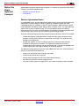
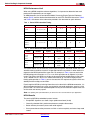
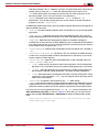
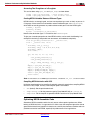
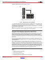
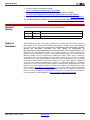
Figure 1 shows the single core Cortex-A9 processor block diagram.
X-Ref Target - Figure 1
3URILOLQJ
0RQLWRU%ORFN
'XDO,QVWUXFWLRQ
'HFRGH6WDJH
,QVWUXFWLRQV
5HJLVWHU
5HQDPH6WDJH
9LUWXDOWR
3K\VLFDO
5HJLVWHU
3RRO
'LVSDWFK6WDJH
$/808/
$/8
,QVWUXFWLRQ
4XHXH
DQG'LVSDWFK
)38RU1(21
%UDQFKHV
2XWRI2UGHU
0XOWL,VVXHZLWK
6SHFXODWLRQ
3UHGLFWLRQV
/RDG6WRUH
$GGUHVV
*HQHUDWLRQ
,QVWUXFWLRQSUHIHWFKVWDJH
0HPRU\6\VWHP
/RDG6WRUH
8QLW
,QVWUXFWLRQ
4XHXH
2XWRIRUGHU:ULWHEDFN6WDJH
&RUH6LJKW
'HEXJ$FFHVV3RUW
%UDQFK
3UHGLFWLRQ
008
7/%
$XWR3UHIHWFKHU
3URJUDP
7UDFH
8QLW
,QVWUXFWLRQ
&DFKH
'DWD&DFKH
;
Figure 1:
Single Core Cortex-A9 Processor Block Diagram
One potential effect of the Cortex-A9 processor is the re-ordering of memory accesses. The
order in which load and store instructions are executed is not necessarily the same as the order
seen in disassembly. Hit-under-miss behaviors in cache mean that a load that goes into (hits)
the cache can complete before a load earlier in the program which missed the cache. Besides
load and store instructions, other instructions can also be executed out-of-order, as long as
there are no dependencies. This makes statically analyzing code sequences very impractical.
For NEON, even though the cycle timing information can be found in the ARM document, it is
difficult to determine how many cycles are needed even for a trivial piece of code. How
instructions move through the pipeline depends not only on the instruction sequence generated
by the compiler but also on the pattern of surrounding instructions. The memory system can
also have a significant effect on the movement of instructions through the pipeline.
Pending memory accesses (such as data loads/store instructions and instruction fetches) that
miss in the cache can stall instructions that are dependent on them for tens of cycles. In
extreme cases, for example, when Dynamic RAM contention or refresh conditions exist, the
latency can increase to hundreds of cycles. Standard data processing instructions usually take
only take one or two cycles, but this can be affected by many factors, and the theoretical
XAPP1206 v1.1 June 12, 2014
www.xilinx.com
4
Before You Begin: Important Concepts
number can be different from the overall performance. The best way to evaluate the
performance of complex application code is to measure it in a real system.
The standard method for improving software performance is to run the software at high speed
for a period of time sufficient for the collection of the performance data. This is accomplished
using profiling tools or the system performance monitor embedded in the Cortex-A9 processor.
With the data collected, you can find which bottleneck or hotspot consumes the most execution
time. Usually, the amount of such code is limited. You can focus on these relatively small pieces
of code and improve the overall performance quickly, with minimal effort.
Profiling tools are usually required for finding bottlenecks. Advanced use of profiling tools is
beyond the scope of this document, but a few solutions are presented to help make you aware
of available options.
Gprof
Gprof is a GNU tool that provides an easy way to profile a C/C++ application. To use it, the
source code must be compiled using GCC with the -pg flag. For line-by-line profiling, the -g
option is also needed. These options add profiling instrumentation to collect data at function
entry and exit at run time. Then you can execute the compiled program and generate profiling
data. After this, gprof analyzes the data and generates meaningful information.
Gprof can only be used to profile code that has been re-built using the -pg option. It cannot be
applied to anything that has not been built for profiling (for example, libc or the kernel). Be
aware that operating system kernel limitations or I/O bottlenecks (such as memory
fragmentation or file accesses) can affect profiling results.
OProfile
OProfile is a Linux whole-system profiling tool that includes the kernel in its metrics. It uses a
statistical sampling method. That is, it examines the system at regular intervals, determines
which code is running, and updates the appropriate counters. Because it uses interrupts, code
that disables interrupts can cause inaccuracies.
OProfile can also be made to trigger on hardware events and record all system activity,
including kernel and library code execution. OProfile does not require code to be recompiled
with any special flags. It can use a Cortex-A9 performance monitor unit (PMU) to provide useful
hardware information, such as clock cycles and cache misses.
ARM DS-5 Streamline
ARM DS-5 Streamline is a GUI-based performance analysis tool for Linux or Android systems.
It is part of ARM DS-5 and consists of a Linux kernel driver, target daemon, and Eclipse-based
UI.
DS-5 Streamline samples the system periodically and reports data visually in a statistical way.
It uses both a hardware performance monitor unit, which has hardware counters for processor
events and Linux kernel metrics to trace application information.
The issue with profiling is that it might require the operating system to be ready. Sometimes, if
you have interest only in a specific algorithm or have a high level of confidence that you know
the location of the bottleneck, you can extract the time-critical codes and run them in
standalone mode. You can try several code sequences to find the one that is most optimal.
Usually, this method requires high-precision timers.
There are some advantages to optimizing code in standalone mode:
•
Easy and convenient
•
No interference from the operating system
•
Fast turn-around
Correctly measuring time is important when using the ARM DS-5 Streamline tool. Usually, highresolution timers are expected. Cortex-A9 processors have one global timer (64-bit) for all
XAPP1206 v1.1 June 12, 2014
www.xilinx.com
5
Before You Begin: Important Concepts
cores, and one private timer (32-bit) for each core. The timers have a pre-scaler to lower the
timer clock rate and to gain longer overflow time, at the cost of timer resolution. The actual timer
clock can be calculated with the following equation:
PERIPHCLK
----------------------------------------------------------------PRESCALERvalue + 1
On the Zynq-7000 AP SoC, the PERIPHCLK is half of CPU clock frequency. This means that
the highest timer resolution is 2 nanoseconds. To make software development easier, Xilinx
also provides APIs for these timers.
NEON Basics
This section examines why and how NEON can be used to improve software performance.
From a software perspective, NEON technology is based on single instruction, multiple data
(SIMD) operations in ARMv7 processors, which implement the advanced SIMD architecture
extensions. This demands a new set of instructions with new functions, and also a new
development methodology. From a hardware perspective, NEON is a separate hardware unit
on Cortex-A series processors, together with a vector floating point (VFP) unit. If an algorithm
can be designed to exploit dedicated hardware, performance can be maximized.
SIMD Introduction
SIMD is a computational technique for processing many data values (generally in powers of
two) in parallel using a single instruction, with the data for the operands packed into special,
wide registers.Therefore, one instruction can do the work of many separate instructions on
single instruction, single data (SISD) architectures. For code that can be parallelized, large
performance improvements can be achieved.
Many software programs operate on large data sets. Each element in a data set can be less
than 32 bits. 8-bit data is common in video, graphics, and image processing, and 16-bit data in
audio codecs. In these contexts, the operations to be performed are simple, repeated many
times, and have little need for control code. SIMD can offer considerable performance
improvements for this type of data processing. It is particularly useful for digital signal
processing or multimedia algorithms, such as:
•
Block-based data processing, such as FFTs, matrix multiplication, etc.
•
Audio, video, and image processing codecs, such as MPEG-4, H.264, On2 VP6/7/8, AVS,
etc.
•
2D graphics based on rectangular blocks of pixels
•
3D graphics
•
Color-space conversion
•
Physics simulations
•
Error correction, such as Reed Solomon codecs, CRCs, elliptic curve cryptography, etc.
On 32-bit microprocessors, such as the Cortex-A series processors, it is relatively inefficient to
run large numbers of 8-bit or 16-bit operations. The processor ALU, registers, and datapath are
designed for 32-bit calculations. If they are used for 8/16-bit operations, additional instructions
are needed to handle overflow. SIMD enables a single instruction to treat a register value as
multiple data elements and to perform multiple, identical operations on those elements.
XAPP1206 v1.1 June 12, 2014
www.xilinx.com
6
Before You Begin: Important Concepts
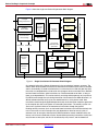
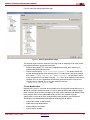
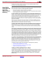
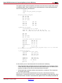
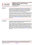
Figure 2 compares SIMD parallel add with 32-bit scalar add.
X-Ref Target - Figure 2
ELW6FDOHU$GG
$
$
%
6,0'3DUDOOHO$GG
&
%
&
$
%
&
$
%
&
$
%
&
$
%
&
$
$
%
&
%
&
;
Figure 2:
Comparing SIMD Parallel ADD with 32-bit Scalar ADD
To achieve four separate additions using scalar operation requires you to use four add
instructions, as shown in Figure 2, and additional instructions to prevent one result from
overflowing into the adjacent byte. SIMD needs only one instruction to do this, and you do not
need to manage the overflow. Moreover, with a dedicated ALU, SIMD instructions generally
require fewer cycles than ARM instructions for the same functions.
Registers
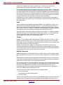
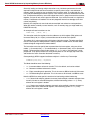
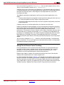
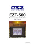
NEON architecture allows for 64-bit or 128-bit parallelism. Its register bank can be viewed as
either sixteen 128-bit registers (Q0-Q15) or as thirty-two 64-bit registers (D0-D31). Each of the
Q0-Q15 registers maps to a pair of D registers.
Figure 3 shows the NEON register bank.
X-Ref Target - Figure 3
'
'
'
'
'
'
4
4
4
;
Figure 3:
NEON Register Bank
NEON and VFP
The Zynq-7000 platform has both NEON and VFP integrated. The key differences between
NEON and VFP are that NEON only works on vectors, but VFP does not, even though it has
“vector” in its name. In fact, calling it a floating-point unit (FPU) can be more appropriate for the
XAPP1206 v1.1 June 12, 2014
www.xilinx.com
7
Before You Begin: Important Concepts
Cortex-A9 processor. For floating-point operation, VFP can support both single-precision and
double-precision, whereas NEON only supports single-precision. VFP can also support more
complex functions, such as square roots, division, and others, but NEON cannot.
NEON and VFP share the thirty-two 64-bit registers in hardware. This means that VFP is
present in VFPv3-D32 form, which has 32 double-precision floating-point registers. This makes
support for context switching simpler. Code that saves and restores VFP contexts also saves
and restores NEON contexts.
Data Types
Data type specifiers in NEON instructions consist of a letter that indicates the type of data and
a number that indicates the width. They are separated from the instruction mnemonic by a
point. The following options are available:
•
Unsigned integer U8 U16 U32 U64
•
Signed integer S8 S16 S32 S64
•
Integer of unspecified type I8 I16 I32 I64
•
Floating-point number F16 F32
•
Polynomial over {0,1} P8
NEON Instruction
All mnemonics for NEON instructions (as with VFP) begin with the letter V. This distinguishes
them from ARM/Thumb instructions. You can use this indicator to find NEON instructions in
disassembly code when checking the efficiency of a compiler. The example below shows the
general format of NEON instructions:
V{<mod>}<op>{<shape>}{<cond>}{.<dt>}(<dest>}, src1, src2
where:
<mod>
One of the previously described modifiers (Q, H, D, R)
<op>
Operation (for example, ADD, SUB, MUL)
<shape>
Shape (L, W or N) [Ref 4]
<cond>
Condition, used with IT instruction
<.dt>
Data type
<dest>
Destination
<src1>
Source operand 1
<src2>
Source operand 2
For a detailed description of each NEON instruction, refer to the NEON Programmers Guide
[Ref 3]. It is strongly recommended that you understand the NEON instruction set because:
•
NEON instructions should be used to the maximum extent when designing algorithms.
Emulating functions with instruction sequences can lower performance significantly.
•
Compilers might not be able to generate optimal code, so you might have to read the
disassembly and determine whether or not the generated code is optimal.
•
Sometimes it is difficult to express certain operations, such as saturation mathematics,
interleaved memory access, table lookup, bitwise multiplex operations, and others, with C
language. So, you might have to use intrinsics or assembler code for these instructions.
•
For time-critical applications, you might have to write NEON assembler code to realize the
best performance.
For more information, see the ARM Architecture Reference Manual [Ref 2] and the Cortex-A
Series Programmer's Guide [Ref 7].
XAPP1206 v1.1 June 12, 2014
www.xilinx.com
8
Before You Begin: Important Concepts
NEON Performance Limit
When using NEON to optimize software algorithms, it is important to determine how much
performance improvement you can expect.
An ARM document, the Cortex-A9 NEON Media Processing Engine Technical Reference
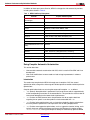
Manual [Ref 4], contains the detailed information for each VFP and NEON instruction. Table 2
and Table 3 are subsets of the information provided in this document for quick reference.
Table 2: Part of VFP Instruction Timing
Name
Format
Cycles
Source
Result
Writeback
VADD
VSUB
.F Sd,Sn,Sm
.D Dd,Dn,Dm
1
-,1,1
4
4
VMUL
.F Sd,Sn,Sm
1
-,1,1
5
5
VNMUL
.D Dd,Dn,Dm
2
-,1,1
6
6
VMLA
.F Sd,Sn,Sm
1
-,1,1
8
8
VMLS
VNMLS
VNMLA
.D Dd,Dn,Dm
2
-,1,1
9
9
Table 3: Part of Advanced SIMD (NEON) Floating-Point Instructions
Name
VADD
VSUB
VABD
VMUL
VMLA
VMLS
Format
Cycles
Source
Result
Writeback
Dd,Dn,Dm
1
-,2,2
5
6
Qd,Qn,Qm
2
-,2,2
-,3,3
5
6
6
7
Dd,Dn,Dm
1
3,2,2
9
10
Qd,Qn,Qm
2
3,2,2
4,3,3
9
10
10
11
The Cycles column lists the number of issued cycles the specific instruction needs and is the
absolute minimum number of cycles if no operand interlocks are present. In other words, this
represents the NEON performance upper limit. For example, in Table 3 you can see that the
NEON floating-point instruction VMUL/VMLA can finish operations on Q registers in just two
cycles. This means that NEON can do four single-precision float multiplications in two cycles.
Thus, if NEON runs at 1 GHz, it can achieve the maximum of 2 GFLOPS single-precision
floating-point operation. In Table 2, you can also see that VFP requires two cycles to finish one
double-precision multiply accumulation.
Even though the NEON cycle timing information can be found in the ARM documentation, it is
difficult to determine how many cycles are required in real-world applications, even for a trivial
piece of code. The actual time required depends not only on the instruction sequence but also
on the cache and memory system.
Note: Use profiling tools (described above) to achieve the most accurate data for your application.
NEON Benefits
The merits of NEON for embedded systems include:
XAPP1206 v1.1 June 12, 2014
•
Simple DSP algorithms can show a larger performance boost (4x-8x)
•
Generally, about 60-150% performance boost on complex video codecs
•
Better efficiency for memory access with wide registers
•
Saves power because the processor can finish a task more quickly and enter sleep mode
sooner
www.xilinx.com
9
Software Performance Optimization Methods
All techniques for programing with NEON listed above are discussed in detail in the following
sections.
Software
Performance
Optimization
Methods
Optimization methods include:
•
Using NEON Optimized Libraries
•
Using Compiler Automatic Vectorization
•
Using NEON Intrinsics
Using NEON Optimized Libraries
The ARM Cortex A9 processor has seen increasing utilization and is one of the most popular
platforms for embedded designs. The processor appears frequently in mobile, tablets, STB,
DTV, telecommunication, industrial control, and other applications. Given the widespread use
of the ARM Cortex A9 processor, a large user community has developed, providing a rich
ecosystem of NEON-optimized software libraries available to software algorithm designers.
Some of related projects are listed in Table 4.
Table 4: NEON Optimized Open Source Libraries
Project Name
Project and Description
Project Ne10
ARM experts optimized vector, matrix, and DSP functions
OpenMAX DL sample
software library released
by ARM
ARMs sample implementation of OpenMAX DL (Development Layer)
software library. It can be used for a wide range of codec and data
computation algorithms
Google WebM
Multimedia codec with NEON assembler optimization.
FFmpeg
A complete, cross-platform solution to record, convert, and stream
audio and video.
x264
A free software library and application for encoding video streams into
the H.264/MPEG-4 AVC compression format.
Android
Components, like Skia library, S32A_D565_Opaque, 5x faster using
NEON.
OpenCV
Library aiming at real-time computer vision
BlueZ
Bluetooth stack for Linux
Pixman
A low-level software library for pixel manipulation. It supports image
compositing, trapezoid rasterization, etc.
Theorarm
An Ogg Theora/Vorbis decoding library optimized for use on ARM
processors. It is based on Theora decoder, as supplied by xiph.org,
and the Tremolo library.
Eigen
C++ template library for linear algebra, including matrices, vectors,
numerical solvers, etc.
FFTW
C library for computing the discrete Fourier transform (DFT) in one or
more dimensions. It supports both real and complex data
Note that this is not an exhaustive list. Table 4 contains only some popular projects because:
XAPP1206 v1.1 June 12, 2014
•
Some projects are meaningful only for special purpose and lack common interest.
•
More and more software projects are moving to NEON optimization. A good example is
OpenCV, which supports NEON in 2.3 (04/07/2011).
•
The software community evolves quickly and new software projects are released
frequently.
www.xilinx.com
10
Software Performance Optimization Methods
In addition to these open source libraries, NEON is also popular with commercial providers,
including those shown in Table 5:
Table 5: NEON 3rd Party Ecosystem
Provider
Project and Description
Sasken Communication
Technologies
H.264, VC1, MPEG-4
Skype
On2 VP6 video, SILK audio (v1.08+)
Ittiam Systems
MPEG-4, MPEG-2, H.263, H.264, WMV9, VC1, DD
Aricent
MPEG-4, H.263, H.264, WMV9, audio
Tata Elxsi
H.264, VC1
SPIRIT DSP
TeamSpirit® Voice and Video Engine
VisualOn
H.264, H.263, S.263, WMV, RealVideo, VC-1
Dolby
Multichannel audio processing, MS10/11
Adobe
Adobe Flash products
Techno Mathematical Co., Ltd.
(TMC)
MPEG-4
drawElements
2D GUI library
ESPICO
Audio: low bitrate and digital theater, consulting
CoreCodec
CoreAVC, CoreMVC, CoreAAC, x264
DSP Concepts
NEON optimized audio and signal processing libraries
Ace Thought Technologies
NEON video and audio
Using Compiler Automatic Vectorization
This section describes:
•
How to enable automatic vectorization with GCC, which is used in Xilinx SDK and Linux
development
•
How small modifications to source code can lead to large improvements in software
performance
Introduction
The easiest way to optimize for NEON is through use of compilers. GCC has several
optimization levels, along with a wide range of individual options to enable or disable particular
optimizations.
Compiler optimization levels are set using the command line option -On, as follows:
XAPP1206 v1.1 June 12, 2014
•
-O0. (default). No optimization is performed. Each line of source code is mapped directly
to the corresponding instructions in the executable file. This provides the clearest view for
source level debugging but the lowest level of performance.
•
-O1. Enables the most common forms of optimization that do not require decisions
regarding size or speed. It can often produce a faster executable than -O0.
•
-O2. Enables further optimizations, such as instruction scheduling. Again, optimizations
that have potential speed versus size implications are not being employed here.
•
-O3. Enables more aggressive optimizations, such as aggressive function inlining, and it
typically increases speed at the expense of image size. Moreover, this option enables
-ftree-vectorize, causing the compiler to attempt to automatically generate NEON
www.xilinx.com
11
Software Performance Optimization Methods
code from standard C or C++. However, in practice, this optimization level cannot always
produce binaries faster than -O2. Check the software performance case-by-case.
•
-Os. Selects optimizations that attempt to minimize the size of the image, even at the
expense of speed. (This is not a point of focus in this document.)
•
-Ofast. Disregards strict standards compliance. '-Ofast' enables all '-O3'
optimizations. It also enables optimizations that are not valid for all standard compliant
programs. It turns on '-ffast-math'.
In addition to the optimization levels, you must set other compiler options to tell the compiler to
generate NEON instructions:
•
-std=c99. The C99 standard introduces some new features that can be used for NEON
optimization.
•
-mcpu=cortex-a9. Specifies the name of the target ARM processor. GCC uses this
name to determine what kind of instructions it can issue when generating assembly code.
•
-mfpu=neon. Specifies which floating-point hardware (or hardware emulation) is
available on the target. Because the Zynq-7000 device has an integrated NEON hardware
unit, and because you plan to use it to accelerate software, you must specify your intention
to the compiler clearly, using the name 'neon'.
•
-ftree-vectorize. Performs loop vectorization on trees. By default, this is enabled at
'-O3'.
•
-mvectorize-with-neon-quad. By default, GCC 4.4 vectorizes for double-word only.
In most cases, using quad-word can better code performance and density, at the cost of
smaller numbers of usable registers.
•
-mfloat-abi=name. Specifies which floating-point ABI is used. Permitted values are:
'soft', 'softfp', and 'hard'.
•
•
'soft' causes the GCC to generate output containing library calls for floating-point
operations. This is used when there are no hardware floating-point units in the system.
•
'softfp' allows the generation of instructions using a hardware floating-point unit,
but still uses the soft-float calling conventions. This results in better compatibility.
•
'hard' allows generation of floating-point instructions and uses FPU-specific calling
conventions. If using the option 'hard', you must compile and link the entire source
code with the same setting.
-ffast-math. This option is not turned on by any '-O' option except
'-Ofast'because it can result in incorrect output for programs that depend on an exact
implementation of IEEE or ISO rules/specifications for math functions. It might, however,
yield faster code for programs that do not require the guarantees of these specifications.
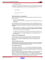
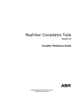
In practice, you can set the optimization level to '-O2' or '-O3' and use the options in the
other optimization flags field, as shown in Figure 4. In Xilinx SDK, you can right-click the
project and click C/C++ Build Settings > Optimization to display the optimization-related
fields.
-mcpu=cortex-a9 -mfpu=neon -ftree-vectorize -mvectorize-with-neon-quad
-mfloat-abi=softfp -ffast-math
XAPP1206 v1.1 June 12, 2014
www.xilinx.com
12
Software Performance Optimization Methods
Figure 4 shows the setting optimization flags.
X-Ref Target - Figure 4
Figure 4:
Setting Optimization Flags
The compiler might not always vectorize C language code as expected, so you must ensure
that compilers generate appropriate instructions:
•
Read the disassembly. This is the most straightforward method, but it requires a full
understanding of NEON instructions.
•
Use the compiler option -ftree-vectorizer-verbose=n. This option controls the
amount of debugging output the vectorizer prints. This information is written to standard
error, unless '-fdump-tree-all' or '-fdump-tree-vect' are specified, in which
case it is output to the usual dump listing file, .vect. For n=0, no diagnostic information is
reported. For n=9, all the information the vectorizer generated during its analysis and
transformation is reported. This is the same verbosity level that
'-fdump-tree-vect-details' uses.
C Code Modifications
Because the C and C++ standards do not provide syntax that specifies parallel behavior, it is
difficult for compilers to determine when it is safe to generate NEON code. Without enough
proof, compilers do not vectorize the code, so you must modify code to provide additional hints
to the compiler. Such source code modifications are within the standard language
specifications, so they do not affect code portability across platforms and architectures.
The following are recommended techniques for modifying code for NEON:
XAPP1206 v1.1 June 12, 2014
•
Indicate the number of loop iterations
•
Avoid loop-carried dependencies
•
Avoid conditions inside loops
•
Use the restrict keyword
www.xilinx.com
13
Software Performance Optimization Methods
•
Use suitable data types
An example of a standard dot product algorithm is used here. The following function calculates
the dot product of two float vectors, with each vector having len number of float type elements.
float dot_product(float * pa, float *
{
float sum=0.0;
unsigned int i;
pb, unsigned int len)
for( i = 0; i < len; i++ )
sum += pa[i] *pb[i];
return sum;
}
Indicate the Number of Loop Iterations
You can write code to permit the compiler to perform otherwise unsafe operations under the
following conditions:
•
A loop has a fixed iteration count
•
The iteration count can be decided as a multiple of N (register length/data type size) at the
coding stage
For the example above: if you know that the value of len is always a multiple of four, you can
indicate this to compiler by masking off the bottom two bits when comparing the loop counter to
len. Because this loop now always executes a multiple of four, the compiler knows it is safe to
vectorize it.
Note: the iteration count as a multiple of four is only an example. In fact, it should be a multiple of the
number of lanes in a vector. For example, if you plan to use the NEON Quad-word register and the
data type is 32-bit float, an iteration count with a multiple of 4 is desired, as indicated by masking off
the 2 low bits as shown in the next code snippet (page 15).
The requirement to have fixed iteration count or iteration count decided at the coding stage is not a
must. When the iteration count can only be decided at run time, you can split the loop into two loops.
One has the iteration count as a multiple of the number of lanes, and another processes the
remaining iterations.
Avoid Loop-Carried Dependencies
If the code contains a loop in which the result of one iteration is affected by the result of
previous iterations, the compiler will be unable to vectorize it. Re-structuring the code, if
possible, to remove any loop-carried dependencies is necessary for the compiler to do
vectorization.
Avoid Conditions Inside Loops
If possible, process data only inside a loop. Generally speaking, it is difficult for the compiler to
vectorize loops containing conditional sequences. In the best of cases, it duplicates the loop,
but in many cases, this kind of code cannot be vectorized at all.
Use the Restrict Keyword
C99 introduced a new keyword, restrict, which can inform the compiler that the location
accessed through a specific pointer is not to be accessed through any other pointer within the
current scope. In other words, the memory regions targeted by the pointers in the current scope
do not overlap with each other.
Without this keyword, the compiler might assume that pointer pa refers to the same location as
pointer pb. This implies the possibility of a loop-carried dependency, which prevents the
compiler from vectorizing the sequence. With the restrict keyword, you inform the compiler
that memory to which pa and pb point does not overlap. The compiler ignores the possibility of
aliasing and assumes that it can vectorize the sequence without creating errors.
XAPP1206 v1.1 June 12, 2014
www.xilinx.com
14
Software Performance Optimization Methods
Using the techniques above, you can modify the C source code to the following style to help the
compiler do automatic vectorization.
float dot_product(float * restrict pa, float *
len)
{
float sum=0.0;
unsigned int i;
restrict pb, unsigned int
for( i = 0; i < ( len & ~3); i++ )
sum += pa[i] *pb[i];
return sum;
}
GCC also supports the alternative forms __restrict__ and __restrict when not
compiling for C99. You can specify the standard used in coding the compiler with the option
-std=C99. Possible standards are c90, gnu99, and others.
Some publications state that manually unrolling the loop, as shown in the example below,
makes automatic vectorization by the compiler easier. However, recent GCC compilers are
better at recognizing and automatically vectorizing the above codes than the manually unrolled
codes. In practice, compilers might not vectorize the manually unrolled loop.
float dot_product(float * restrict pa, float *
len )
{
float sum[4]={0.0,0.0,0.0,0.0};
unsigned int i;
for(i = 0; i < ( len & ~3); i+=4)
{
sum[0] += pa[i] *pb[i];
sum[1] += pa[i+1] *pb[i+1];
sum[2] += pa[i+2] *pb[i+2];
sum[3] += pa[i+3] *pb[i+3];
}
return sum[0]+sum[1]+sum[2]+sum[3];
}
restrict pb, unsigned int
Use Suitable Data Types
When optimizing algorithms operating on 16-bit or 8-bit data without SIMD, treating the data as
32-bit variables can sometimes yield better performance. This is because the compiler must
generate additional instructions to ensure the result does not overflow by a half-word or byte.
However, when targeting automatic vectorization with NEON, using the smallest data type that
can hold the required values is always the best choice. In a given time period, the NEON engine
can process twice as many 8-bit values as 16-bit values. Also, some NEON instructions do not
support some data types, and some only support certain operations. For example, NEON does
not support double-precision floating-point data types, so using a double-precision where a
single-precision float is adequate can prevent the compiler from vectorizing code. NEON
supports 64-bit integers only for certain operations, so avoid use of long variables where
possible.
NEON includes a group of instructions that can perform structured load and store operations.
These instructions can only be used for vectorized access to data structures where all
members are of the same size. Accessing 2/3/4-channel interleaved data with these
instructions can also accelerate NEON memory access performance.
Deviation of NEON Computation Results
For integers, the order of computation does not matter. For example, summing an array of
integers forward or backward always produces the same result. However, this is not true for
floating-point numbers because of the coding precision. Thus, the NEON-optimized code might
XAPP1206 v1.1 June 12, 2014
www.xilinx.com
15
Software Performance Optimization Methods
produce a result different from non-NEON optimized code for floating-point numbers. Typically,
however, the difference is not significant. When you need to validate the code by comparing the
computational result, be aware that the term “equal” for a data type of float or double does not
mean exactly the same thing, but the difference is acceptable.
Lab 1
1. Create a new project in SDK.
2. Import lab1 source files.
3. Run the application on hardware, and check the output on the console.
4. Open the generated ELF file to check how the instructions are being generated.
5. Observe the following:
-
The manually unrolled loop is vectorized and takes more time.
-
The execution time of the automatic vectorized codes is about 10.8 s, even when the
optimization level is set to -O3, and NEON automatic vectorization is enabled.
-
When optimization levels are set to -O3, PLD instructions are inserted. (This is
discussed later.)
Using NEON Intrinsics
NEON C/C++ intrinsics are available for armcc, GCC/g++, and llvm. Because they use the
same syntax, source code that uses intrinsics can be compiled by any of these compilers and
provide excellent code portability.
Essentially, NEON intrinsics are a C function wrapper of NEON assembler instructions. They
provide a way to write NEON code that is easier to maintain than NEON assembler code, while
preserving fine-granularity control of the generated NEON instructions. In addition, there are
new data type definitions that correspond to NEON registers (both D-registers and Q-registers)
containing different sized elements, allowing C variables to be created that map directly onto
NEON registers. These variables can be passed to NEON intrinsic functions directly. The
compiler then generates NEON instructions instead of incurring an actual subroutine call.
NEON intrinsics provide low-level access to NEON instructions but with the compiler doing
some of the hard work normally associated with writing assembly language, such as:
•
Register allocation.
•
Code scheduling or re-ordering instructions to achieve the highest performance. The C
compilers can be told which processor is being targeted, and they can reorder code to
ensure the CPU pipeline is running in an optimized way.
The main disadvantage with intrinsics is that you cannot force the compiler to output exactly the
code you want. So in some cases, there is still a possibility of further improvement by using
NEON assembler code.
For details about NEON intrinsics, see the following:
•
RealView Compilation Tools Compiler Reference Guide [Ref 9]
•
GCC documentation [Ref 10]
NEON Types in C
The ARM C Language Extensions [Ref 9] contains a full list of NEON types. The format is:
<basic type>x<number of elements>_t
To use NEON types and intrinsics, a header file, arm_neon.h, must be included.
XAPP1206 v1.1 June 12, 2014
www.xilinx.com
16
Software Performance Optimization Methods
Table 6 can give developers some basic ideas about NEON types.
Table 6: NEON Type Definitions
64-bit type (D-register)
128-bit type (Q-register)
int8x8_t
int8x16_t
int16x4_t
int16x8_t
int32x2_t
int32x4_t
int64x1_t
int64x2_t
uint8x8_t
uint8x16_t
uint16x4_t
uint16x8_t
uint32x2_t
uint32x4_t
uint64x1_t
uint64x2_t
float16x4_t
float16x8_t
float32x2_t
float32x4_t
poly8x8_t
poly8x16_t
poly16x4_t
poly16x8_t
There are also combination types, which include two, three, or four of each of the above in a
larger ‘struct’ type. These types are used to map the registers accessed by NEON
load/store operations, which can load/store up to four registers in a single instruction. For
example:
struct int16x4x2_t
{
int16x4_t val[2];
}<var_name>;
These types are only used by loads, stores, transpose, interleave, and de-interleave
instructions. To perform operations on the actual data, select the individual registers using the
syntax shown below:
<var_name>.val[0] and <var_name>.val[1]
Techniques Specific to NEON Intrinsics
Declaring a Variable
Example:
uint32x2_t vec64a, vec64b; // create two D-register variables
Using Constants
The following code replicates a constant into each element of a vector:
uint8x8 start_value = vdup_n_u8(0);
To load a general 64-bit constant into a vector:
uint8x8 start_value =
vreinterpret_u8_u64(vcreate_u64(0x123456789ABCDEFULL));
Moving Results Back to Normal C Variables
To access a result from a NEON register, you can store it to memory using VST or move it back
to ARM using a get lane type operation:
result = vget_lane_u32(vec64a, 0); // extract lane 0
XAPP1206 v1.1 June 12, 2014
www.xilinx.com
17
Software Performance Optimization Methods
Accessing Two D-registers of a Q-register
This can be done using vget_low and vget_high, as shown below:
vec64a = vget_low_u32(vec128); // split 128 bit vector
vec64b = vget_high_u32(vec128); // into 2x 64 bit vectors
Casting NEON Variables Between Different Types
NEON intrinsics are strongly typed, and you cannot perform type casts as freely as you can in
C language. If there must be casts between vectors of different types, use vreinterpret,
which does not actually generate any code but does enable you to cast the NEON types:
uint8x8_t byteval;
uint32x2_t wordval;
byteval = vreinterpret_u8_u32(wordval);
Note that the destination type u8 is listed first after vreinterpret.
To give you a broader perspective on how NEON intrinsics can be used, the following is an
example of calculating a dot product from two vectors, with moderate complexity:
float dot_product_intrinsic(float * __restrict vec1,
float * __restrict vec2, int n)
{
float32x4_t vec1_q, vec2_q;
float32x4_t sum_q = {0.0, 0.0, 0.0, 0.0};
float32x2_t tmp[2];
float result;
for( int i=0; i<( n & ~3); i+=4 )
{
vec1_q=vld1q_f32(&vec1[i]);
vec2_q=vld1q_f32(&vec2[i]);
sum_q = vmlaq_f32(sum_q, vec1_q, vec2_q );
}
tmp[0] = vget_high_f32(sum_q);
tmp[1] = vget_low_f32 (sum_q);
tmp[0] = vpadd_f32(tmp[0], tmp[1]);
tmp[0] = vpadd_f32(tmp[0], tmp[0]);
result = vget_lane_f32(tmp[0], 0);
return result;
}
Note: As stated above, to use NEON types and intrinsics, a header file, arm_neon.h, must be included.
Compiling NEON Intrinsics with GCC
Unlike the complex options for compiling C code with automatic vectorization, compiling NEON
intrinsics is fairly simple, and only a few compiler options are needed:
•
-On. (default). Set the optimization levels.
•
-mcpu=cortex-a9. Set the processor type for Zynq-7000 AP SoC as 'cortex-a9'
•
-mfpu=neon. Tell the compiler to generate NEON instructions for Zynq-7000 AP SoC.
Optimizing NEON Assembler Code
Sometimes NEON assembler code is the only way to achieve optimal performance. When
looking at NEON intrinsics, it is apparent that in some cases the compiler might not be able to
generate the fastest binary possible. In these cases, carefully hand-written assembler code can
yield the best results from NEON, especially for performance-critical applications.
XAPP1206 v1.1 June 12, 2014
www.xilinx.com
18
Software Performance Optimization Methods
The disadvantage is obvious. First, it is difficult to maintain assembler code. Even though all
Cortex-A series processors support NEON instructions, the hardware implementations are
different, so instruction timing and movement in the pipeline are different. This means that
NEON optimization is processor-dependent. Code running faster on one Cortex-A series
processor might not work as well on another Cortex-A series processor. Second, it is difficult to
write assembler code. To be successful, you must know the details of the underlying hardware
features, such as pipelining, scheduling issues, memory access behavior, and scheduling
hazards. These factors are briefly described below.
Memory Access Optimizations
Typically, NEON is used to process large amounts of data. One crucial optimization is to ensure
that the algorithm uses cache in the most efficient way possible. It is also important to consider
the number of active memory locations. A typical optimization is one in which you design the
algorithm to process small memory regions called tiles, one by one, to maximize the cache and
translation lookaside buffer (TLB) hit rate, and to minimize memory access to external Dynamic
RAM.
NEON includes instructions that support interleaving and de-interleaving, and can provide
significant performance improvements in some scenarios, if used properly. VLD1/VST1
loads/stores multiple registers to/from memory, with no de-interleaving. Other VLDn/VSTn
instructions allow you to interleave and de-interleave structures containing two, three, or four
equally sized elements.
Alignment
Even though NEON architecture provides full unaligned support for NEON data access,
instruction opcode contains an alignment hint which permits implementations to be faster when
the address is aligned and a hint is specified.
The base address specified as [<Rn>:<align>]
In practice, it is also useful to arrange the data as cache line aligned. Otherwise, when the data
crosses cache line boundaries, additional cache line fill might be incurred, and the overall
system performance drops.
Instruction Scheduling
To write faster code for NEON, you must be aware of how to schedule code for the specific ARM
processor. For the Zynq-7000 AP SoC, this would be the Cortex-A9.
Result-use scheduling is the main performance optimization when writing NEON code. NEON
instructions typically issue in one or two cycles, but the result is not always ready in the next
cycle (except when the simplest NEON instructions are issued, such as VADD and VMOV).
Some instructions have considerable latency, for example the VMLA multiply-accumulate
instruction (five cycles for an integer; seven cycles for a floating-point). To prevent a stall, take
into consideration the amount of time between the current instruction and the next one using its
result. Despite having a few cycles result latency, these instructions are fully pipelined, so
several operations can be in flight at once.
Another typical scheduling issue is interlock. Without adequate hardware knowledge, it is
possible to load the data from memory to registers, then process them immediately. If the
memory access receives a cache hit, there is no problem. However, if a cache hit is missed, the
CPU must wait tens of cycles to load data from external memory into the cache before
proceeding. Thus, you usually need to place instructions that are not dependent upon the VLD
instruction between the VLD and the instruction using its result. Using the Cortex-A9 preload
engine can improve the cache hit rate. This is discussed later.
Also be aware that external memory is slow and has a long latency compared to on-chip
memory. The CPU uses cache and write buffers to alleviate this issue. Sometimes, if there are
long bursts of memory write, the write buffer fills up, and the next VST instruction stalls.
XAPP1206 v1.1 June 12, 2014
www.xilinx.com
19
Boost NEON Performance by Improving Memory Access Efficiency
Therefore, when writing assembly instructions, it is best to distribute memory access
instructions with data processing instructions.
Boost NEON
Performance by
Improving
Memory Access
Efficiency
When talking about processor core performance, developers typically make some assumptions
that are not always accurate in real-world applications, specifically:
•
The processor pipeline is optimal and there is no interlock.
•
The memory subsystem is ideal (zero wait state), that is, the processor does not need to
wait for memory to return data or instructions.
On-chip static RAM is very fast, but too costly, and you cannot integrate large RAM sizes into
the SoC. To lower the bill of materials (BOM) cost, dynamic RAM is often used as the main
memory. In the past decade, processor clock frequencies have evolved at a much faster pace
than dynamic RAM. The slower dynamic RAM can make the high clock frequency of a
processor less meaningful. Another issue with dynamic RAM is that it normally has a long
latency to return data. For a CPU, this is a serious issue because a CPU is more sensitive to
latency than throughput.
When the memory subsystem cannot return the data or instructions needed by processor
cores immediately, processors have nothing to do but wait. The out-of-order execution of an
ARM Cortex-A9 core can alleviate this issue, but it still exists.
To reduce the gap between processor and memory subsystems, engineers introduced cache
into modern SoCs. Cache is made up of fast on-chip static RAM and a cache controller to
determine when data can be moved in or out. But cache is not a panacea for embedded
systems. To use it efficiently, you need to know some details about the underlying hardware
system.
Cache improves system performance by temporal and spatial locality. Temporal locality means
that a resource accessed now will be accessed again in the near future. Spatial locality means
that the likelihood of accessing a resource is higher if a resource near it was just referenced.
When the data needed by the CPU can be found in cache, it is called a cache hit. Cache can
return the data with low latency. When the data is not in cache, it is called a cache miss, and the
cache controller must fetch the data into cache first and then return it to the CPU. This results
in much longer latency, and thus lower actual CPU performance. Preloading data into cache
before actually using it can improve the cache hit rate, thus improving system performance. The
ARM Cortex-A9 implements a preload engine and provides instructions to do this.
In a real SoC, cache is implemented as a trade-off between performance and complexity. Direct
mapped cache is simple but low efficiency. Fully associative cache has the highest efficiency, at
the cost of very complicated hardware design. In practice, N-way set associative cache is
frequently used. There is one potential issue with this. If the code is not well written, cache
thrashing can occur, and that can lower system performance significantly. In this case, you
must access data as tiles to improve the cache hit rate.
The following sections introduce some techniques for improving memory efficiency:
•
Loading and Storing Multiple Data in a Burst
•
Using the Preload Engine to Improve the Cache Hit Rate
•
Using Tiles to Prevent Cache Thrashing
Loading and Storing Multiple Data in a Burst
Loading and storing multiple instructions allows successive words to be read from or written to
memory. These are extremely useful for stack push/pop and for memory copying. Only word
values can be operated in this way on a word aligned address. The operands are a base
register (with an optional denoting write-back of the base register) with a list of registers
between braces.
XAPP1206 v1.1 June 12, 2014
www.xilinx.com
20
Boost NEON Performance by Improving Memory Access Efficiency
Generally, loading and storing multiple instructions can yield better performance than the
equivalent multiple load-and-store instructions, especially when cache is not enabled or a
memory region is marked as non-cacheable in the translation table. To understand this, you
must study the AMBA® specification carefully. Each memory access has overhead on the AXI
bus. To improve bus efficiency, use an AXI support burst; that is, group N consecutive accesses
together, and you will only need a one-time overhead. If you access N words in a single-beat
manner, N overheads are needed. This not only degrades internal bus throughput, but also
causes long latency.
Normally, the compiler only uses load-and-store multiple instructions for stack operations.
When the routine is memory-access intensive, such as memory copy, you might need to try
LDM/STM manually.
An example of these instructions can be:
LDMIA R10!, { R0-R3, R12 }
This instruction reads five registers from the addresses at which register (R10) points and
increases R10 by 20 (5 × 4 bytes) at the end because of the write-back specifier.
The register list is comma separated, with hyphens indicating ranges. The order specified in
this list is not important. ARM processors always proceed in a fixed fashion, with the lowest
numbered register mapped to the lowest address.
The instruction must also specify how to proceed from the base register, using one of four
modes: IA (increment after), IB (increment before), DA (decrement after), and DB (decrement
before). These specifiers also have four aliases (FD, FA, ED and EA) that work from a stack
perspective. They specify whether the stack pointer points to a full or empty top of the stack,
and whether the stack ascends or descends in memory.
Correspondingly, NEON supports load/store multiple in a similar way. For example:
VLDMmode{cond} Rn{!}, Registers
VSTMmode{cond} Rn{!}, Registers
The Mode should be one of the following:
•
IA - Increment address after each transfer. This is the default, and can be omitted.
•
DB - Decrement address before each transfer.
•
EA - Empty ascending stack operation. This is the same as DB for loads and IA for saves.
•
FD - Full descending stack operation. This is the same as IA for loads, and DB for saves.
Note that NEON has some special instructions for interleaving and de-interleaving:
XAPP1206 v1.1 June 12, 2014
•
VLDn (Vector load multiple n-element structures) loads multiple n-element structures from
memory into one or more NEON registers, with de-interleaving (unless n == 1). Every
element of each register is loaded.
•
VSTn (Vector store multiple n-element structures) writes multiple n-element structures to
memory from one or more NEON registers, with interleaving (unless n == 1). Every
element of each register is stored.
www.xilinx.com
21
Boost NEON Performance by Improving Memory Access Efficiency
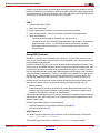
A graphical demonstration of VST3 is shown in Figure 5.
X-Ref Target - Figure 5
>5@
[
\
]
[
\
]
[
\
]
[
[
[
[
'
\
\
\
\
'
]
]
]
]
'
967^'''`>5@
;
Figure 5:
Demonstration of VST3 Operation
VLD2 loads two or four registers, de-interleaving even and odd elements. This could be used,
for example, to split left and right channel stereo audio data. Similarly, VLD3 could be used to
split RGB pixels or XYZ coordinates into separate channels. Correspondingly, VLD4 could be
used with ARGB or CMYK images.
Note: These special NEON instructions cannot be expressed by pure C language. You must use NEON
intrinsics or assembler code to have the compiler generate machine instructions.
Using the Preload Engine to Improve the Cache Hit Rate
ARM Cortex-A9 processors support speculation and out-of-order execution, which can hide
latencies associated with memory accesses. However, accesses to the external memory
system are usually so slow that there is still some penalty. If you can pre-fetch instructions or
data into the cache before you need them, you can minimize CPU stall time and maximize CPU
performance.
From a hardware perspective, all preload instructions are handled by a dedicated unit in the
Cortex-A9 processor with dedicated resources. This avoids using resources in the integer core
or the load store unit.
From a software perspective, cache preloading means three instructions, PLD (data cache
preload), PLI (instruction cache preload) and PLDW (preload data with intent to write). The PLD
instruction might generate a cache line-fill on a data cache miss, while the processor continues
to execute other instructions. If used correctly, PLD can significantly improve performance by
hiding memory access latencies. There is also a PLI instruction that enables you to give the
processor hints that an instruction load from a particular address is likely to happen soon. This
can cause the processor to preload the instructions to its instruction cache.
Lab 2
1. Create a new project in Xilinx SDK.
2. Import the lab 2 source files.
3. Run the source files on hardware.
4. Observe the performance improvement you have obtained.
XAPP1206 v1.1 June 12, 2014
www.xilinx.com
22
Boost NEON Performance by Improving Memory Access Efficiency
The algorithm used is still the dot product calculation on two float vectors (length=1024), written
in assembler codes. There are two versions: preload optimized, and non-preload optimized
with all PLD instructions commented out.
.align 4
.global neon_dot_product_vec16_pld
.arm
neon_dot_product_vec16_pld:
pld [r0, #0]
pld [r1, #0]
pld [r0, #32]
pld [r1, #32]
vmov.i32
vmov.i32
vmov.i32
vmov.i32
q10,
q11,
q12,
q13,
#0
#0
#0
#0
.L_mainloop_vec_16_pld:
@ load current set of values
vldm r0!, {d0, d1, d2, d3, d4, d5, d6, d7}
vldm r1!, {d10, d11, d12, d13, d14, d15, d16, d17}
pld
pld
pld
pld
[r0]
[r1]
[r0, #32]
[r1, #32]
@ calculate values for current set
vmla.f32
q10, q0, q5
vmla.f32
q11, q1, q6
vmla.f32
q12, q2, q7
vmla.f32
q13, q3, q8
@ loop control
subs
r2, r2, #16
bgt
.L_mainloop_vec_16_pld @ loop if r2 > 0, if we have
more elements to process
.L_return_vec_16_pld:
@ calculate the
vadd.f32
vadd.f32
vadd.f32
vpadd.f32
vpadd.f32
vmov.32
@ return
bx
final result
q15, q10, q11
q15, q15, q12
q15, q15, q13
d30, d30, d31
d30, d30, d30
r0, d30[0]
lr
On the console, you can see the execution time and observe the following:
•
Non-preload optimized assembler functions take approximately 11.8 s to execute. This is
a little slower than compiler optimization because the above example is for demonstration
purposes and does not use other low-level optimization techniques.
•
Preload optimized assembler functions take around 9.5 s to execute. This is better than
the compiler optimization.
Now you can check the software performance on hot cache. Lab2 focuses on testing
performance in a conservative way, that is, it makes the assumption of using cold cache. Cold
cache means there is no data in cache when the algorithm starts. The coding associated with
XAPP1206 v1.1 June 12, 2014
www.xilinx.com
23
Boost NEON Performance by Improving Memory Access Efficiency
this is at line 67 of the source file benchmarking.c. You can see that before each run, the L1
and L2 cache is flushed by function call Xil_DCacheFlush().
Comment out this line to see the hot cache performance. The execution drops to around 2.67
s, demonstrating that cache can improve performance significantly. In this example, because
the latency for PLD instructions is much longer than the computation time, not all PLD
instructions take effect.
Two additional methods for improving the cache hit rate and system performance are as
follows:
•
Create a preload routine for the algorithm to load some of the leading data into cache and
run it some time before the actual algorithm computation routine.
•
Increase the preload advancement steps in the actual algorithm computation to make the
preload continuous.
If properly tuned, you can achieve performance very close to that of hot cache.
However, to efficiently use data preloading, you must consider what the lead time should be. If
preload is done too early, the preloaded data might be ejected because of other code. If it is too
late, the data might not be available in cache when needed and thus lower system
performance. The key factor is the main memory access latency. Fortunately, you do not need
to write code to test it. The open source project lmbench already has test code identify this
parameter in an embedded system. For a typical Zynq device configuration (CPU runs at 667
MHz, DDR3 runs at 533 MHz), the latency is about 60 to 80 CPU cycles. This provides
adequate information about where to insert the preload routine before the actual computation
routine.
You can also try to optimize memcpy(), written by C with data preloading. The performance
boost is around 25%. This is not as significant as the above because there is no computation
to compensate the data preload latency.
Using Tiles to Prevent Cache Thrashing
For Zynq-7000 devices, each of the two Cortex-A9 processors has separate 32 KB level-1
instruction and data caches, and both caches are 4-way set-associative. The L2 cache is
designed as an 8-way set-associative 512 KB cache for dual Cortex-A9 cores. These
parameters are critical to predicting when cache thrashing will occur.
Before trying to identify a solution, you need to know why the issue occurs. Start with the
simplest cache implementation first, a direct mapped cache.
In a direct-mapped cache (shown in Figure 6 ), each location in main memory maps to a single
location in the cache. The following figure shows a simplified small cache (64 bytes) example,
with four words per line and four lines. In this example, address bits [3:2] act as the offset to
select a word within a cache line, and address bits [5:4] act as the index to select one of the four
available cache lines. Address bits [31:6] are used as a tag value for each cache line.
XAPP1206 v1.1 June 12, 2014
www.xilinx.com
24
Boost NEON Performance by Improving Memory Access Efficiency
X-Ref Target - Figure 6
0DLQ0HPRU\
&DFKH
[
[
[
[
[
[
ELW$GGUHVV
[
7DJ
,QGH[2IIVHW%\WH
[
/LQHV,QGH[
[
[
'DWD
+LW
;
Figure 6:
Direct Mapped Cache
In Figure 6, you can see the 16-byte arrays with starting addresses 0x0, 0x40 and 0x80 share
the same cache line. This means that at any given time, only one of those lines can be in the
cache.
Consider a loop similar to the following, with pointers result, data1, and data2 pointing to
0x00, 0x40 and 0x80 respectively.
void add_array(int *data1, int *data2, int *result, int size)
{
int i;
for (i=0 ; i<size ; i++) {
result[i] = data1[i] + data2[i];
}
When the code starts running, something similar to the following occurs:
•
Address 0x40 is read first. As it is not in cache, a line-fill takes place by putting the data
from 0x40 to 0x4F into the cache.
•
Then, address 0x80 is read. It is not in cache and so a line-fill takes place by putting the
data from 0x80 to 0x8F into the cache and evicting the data from addresses 0x40 to
0x4F out of the cache.
•
The result is written to 0x00. Depending on the cache allocation policy, this might cause
another line fill. The data from 0x80 to 0x8F might be evicted out of the cache.
•
The same thing can happen again and again on each iteration of the loop. You can see
that the cache content re-use is almost nothing and the software performance could be
very poor.
This issue is called cache thrashing. It is very easy for cache thrashing to occur on
direct-mapped cache, so it is seldom used in real designs.
XAPP1206 v1.1 June 12, 2014
www.xilinx.com
25
Boost NEON Performance by Improving Memory Access Efficiency
Fully associative cache can solve this issue. With this solution, any specific location in main
memory can be stored in any cache line. However, building such a cache is impractical unless
it is very small. The control hardware can be complex and the power consumption high.
In practice, N-way set associative cache is more widely used to balance complexity and
performance. In this solution, cache is divided into N pages and each location in main memory
can be stored in N possible locations in the cache.
In fact, fully associative cache can be regarded as N-way set associative, where N is the
quotient of cache size divided by cache line size. Studies on the choice of N show performance
improvements are minimal for level 1 caches above 4-way associativity, and 8-way or 16-way
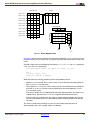
associativity are appropriate for larger level 2 caches. Figure 7 is a simple diagram showing the
structure of a 4-way set associative cache.
X-Ref Target - Figure 7
2IIVHW
/LQH
'DWD5$0
7DJ5$0
,QGH[
6HW
:D\
7DJ
;
Figure 7:
Structure of a 4-way Set Associative Cache
But even for the fully associative cache, the cache thrashing issue, though alleviated, still exists
in extreme conditions. For example, with the above code example running on a 4-way set
associative cache, when the number of source vectors exceeds four (even three, depending on
the cache allocation policy), cache thrashing occurs.
A typical scenario for this issue is accessing elements in the same column sequentially within
a two-dimensional array. The document Cortex-A Series Programmer's Guide [Ref 7] provides
an example of matrix multiplication. Below is a straightforward code example for matrix
multiplication:
for(i=0;i<N;i++)
for(j=0;j<N;j++)
for(k=0;k<N;k++)
result[i][j] += a[i][k]*b[k][j];
In this case, the contents of matrix a are accessed sequentially, but accessing matrix b
advances by row. Therefore, cache misses are likely while accessing each element in matrix b
because matrix sizes are so large that the cache cannot contain them.
To solve this issue, divide the large matrix into smaller partitions and confine the computations
within these smaller partitions. The partitions are also known as tiles. Here you assume the
data type for matrix is int. For Cortex-A9 processors, the L1 cache line is 32 bytes, so one L1
cache line can hold eight elements. In this case you can rewrite the code using 8*8 tiles to
improve cache hit rates. Below is an example of optimized code:
for (io = 0; io < N; io += 8)
for (jo = 0; jo < N; jo += 8)
for (ko = 0; ko < N; ko += 8)
for (ii = 0, rresult = &result[io][jo], ra = &a[io][ko];
XAPP1206 v1.1 June 12, 2014
www.xilinx.com
26
Summary
ii < 8; ii++, rresult += N, ra += N)
for (ki = 0, rb = &b[ko][jo];ki < 8; ki++, rb += N)
for (ji = 0; ji < 8; ji++)
rresult[ji] += ra[ki] * rb[ji];
Lab 3
1. Create a new project, import lab 3 source files.
2. Run the standalone application on board.
3. In the code provided, set the matrix size to 512*512, so that the execution does not take too
long.
Note: Because the focus is on how tiling can improve performance, you do not enable compiler
automatic vectorization for NEON in this lab.
The optimization level is set to -O2, and the optimization flags are set to -std=c99.
4. After executing lab3, you can see that:
-
The non-tiling implementation takes approximately 7.9 seconds.
-
The tiling implementation only takes about 2.1 seconds.
-
The performance improvement is significant.
Because NEON is often used to process large data sets, properly changing an algorithm with
the tiling technique can produce higher cache hit rates, thus much better performance. You can
also try using compiler automatic vectorization in your projects to achieve additional (more
modest) improvements. As demonstrated in lab1, compilers are not good at automatic
vectorization on complex loops. If more performance gain is needed, you must perform manual
optimization on computations within tiles.
Summary
This application note introduces four methods for improving software performance using NEON
on a Cortex-A9 processor core. Because NEON is typically used on large data sets, cache
performance is critical to system performance. Also discussed are three ways to improve data
exchanges between the CPU, cache, and main memory. Software optimization is a complex
topic. To realize optimal performance from hardware, you must apply all these techniques
together and properly balance them.
References
This application note uses the following references:
1. Zynq-7000 All Programmable SoC: Concepts, Tools, and Techniques (UG873)
www.xilinx.com/support/documentation/sw_manuals/xilinx14_7/ug873-zynq-ctt.pdf
2. ARM® Architecture Reference Manual, ARMv7-A and ARMv7-R edition
silver.arm.com/download/download.tm?pv=1299246
3. NEON Programmer’s Guide
http://infocenter.arm.com/help/index.jsp?topic=/com.arm.doc.den0018a/index.html
4. Cortex™-A9 NEON™ Media Processing Engine Technical Reference Manual
infocenter.arm.com/help/topic/com.arm.doc.ddi0409g/DDI0409G_cortex_a9_neon_mpe_
r3p0_trm.pdf
5. Cortex™-A9 Technical Reference Manual
infocenter.arm.com/help/topic/com.arm.doc.ddi0388g/DDI0388G_cortex_a9_r3p0_trm.pd
f
6. Cortex™-A9 MPCore® Technical Reference Manual
infocenter.arm.com/help/topic/com.arm.doc.ddi0407g/DDI0407G_cortex_a9_mpcore_r3p
0_trm.pdf
XAPP1206 v1.1 June 12, 2014
www.xilinx.com
27
Revision History
7. Cortex™-A Series Programmer's Guide
silver.arm.com/download/download.tm?pv=1296010
8. Zynq-7000 All Programmable SoC Technical Reference Manual (UG585)
www.xilinx.com/support/documentation/user_guides/ug585-Zynq-7000-TRM.pdf
9. RealView Compilation Tools Compiler Reference Guide, available at infocenter.arm.com.
10. GCC documentation, available at gcc.gnu.org/onlinedocs/gcc/ARM-NEON-Intrinsics.html
Revision
History
Notice of
Disclaimer
XAPP1206 v1.1 June 12, 2014
The following table shows the revision history for this document.
Date
Version
Description of Revisions
05/28/2014
1.0
Initial Xilinx release.
06/12/2014
1.1
Editorial changes to Table 4 and Table 5.
The information disclosed to you hereunder (the “Materials”) is provided solely for the selection and use of
Xilinx products. To the maximum extent permitted by applicable law: (1) Materials are made available "AS
IS" and with all faults, Xilinx hereby DISCLAIMS ALL WARRANTIES AND CONDITIONS, EXPRESS,
IMPLIED, OR STATUTORY, INCLUDING BUT NOT LIMITED TO WARRANTIES OF
MERCHANTABILITY, NON-INFRINGEMENT, OR FITNESS FOR ANY PARTICULAR PURPOSE; and (2)
Xilinx shall not be liable (whether in contract or tort, including negligence, or under any other theory of
liability) for any loss or damage of any kind or nature related to, arising under, or in connection with, the
Materials (including your use of the Materials), including for any direct, indirect, special, incidental, or
consequential loss or damage (including loss of data, profits, goodwill, or any type of loss or damage
suffered as a result of any action brought by a third party) even if such damage or loss was reasonably
foreseeable or Xilinx had been advised of the possibility of the same. Xilinx assumes no obligation to
correct any errors contained in the Materials or to notify you of updates to the Materials or to product
specifications. You may not reproduce, modify, distribute, or publicly display the Materials without prior
written consent. Certain products are subject to the terms and conditions of the Limited Warranties which
can be viewed at http://www.xilinx.com/warranty.htm; IP cores may be subject to warranty and support
terms contained in a license issued to you by Xilinx. Xilinx products are not designed or intended to be
fail-safe or for use in any application requiring fail-safe performance; you assume sole risk and liability for
use of Xilinx products in Critical Applications: http://www.xilinx.com/warranty.htm#critapps.
www.xilinx.com
28