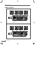
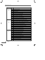
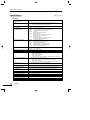
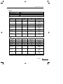
1
PX-1650_E 2003.9.8 10:42 AM 페이지2
PX-1650
Stereo Built In X-OVER
PX-1650_E 2003.9.8 10:42 AM 페이지3
Contents
1. Introduction/Unpacking and Installation .................................................................................1
2. Features ................................................................................................................................2
3. Precautions............................................................................................................................3
4. Front Panel Controls...............................................................................................................4
5. Top Panel Controls .................................................................................................................9
6. Rear Panel Controls .............................................................................................................12
7. Speaker Connections............................................................................................................14
8. Operating Tips.....................................................................................................................17
9. Applications ........................................................................................................................26
10. Block Diagram...................................................................................................................27
11. Specifications.....................................................................................................................28
OFFICE :
226-9 DUGJUNG - LI, HOE CHUN - EUB,
YANGJU - KUN, KYUNGKI - DO, KOREA
TEL : 82-351-860-7041~5, FAX : 82-351-858-1907
Home Page : http://www.inter-m.co.kr, http://www.inter-m.com
E-mail : [email protected]
PX-1650_E 2003.9.8 10:42 AM 페이지4
STEREO BUILT IN X-OVER
Introduction
Thank you for purchasing a PX-1650 Stereo Quad Powered Mixer Built in X-OVER. The PX-1650 Series
provides an excellent balance of operability, functionally and ease of use. In order to take full advantage of
the PX-1650 Series capabilities and enjoy years of trouble-free use, please read this manual carefully.
Unpacking and Installation
Although it is neither complicated to install nor difficult to operate your set, a few minutes of your time is
required to read this manual for a properly wired installation and becoming familiar with its many features
and how to use them. Please take a great care in unpacking your set and do not discard the carton and
other packing materials. They may be needed when moving your set and are required if it ever becomes
necessary to return your set for service.
Never place the unit near radiators, in front of heating vents, to direct sun light, in excessive humid or dusty
location to avoid early damage and for your years of quality entertainment. Connect your complementary
components as illustrated in the following page.
CAUTION
RISK OF ELECTRIC SHOCK
DO NOT OPEN
CAUTION: TO REDUCE THE RISK OF ELECTRIC SHOCK.
DO NOT REMOVE COVER (OR BACK).
This symbol is intended to alert the user to the
presence of uninsulated “dangerous voltage”
within the product’s enclosure that may be of sufficient magnitude to constitute a risk of electric
shock to persons.
This symbol is intended to alert the user to the
presence of important operation and maintenance (servicing) instructions in the literature
accompanying the appliance.
NO USER-SERVICEABLE PARTS INSIDE.
REFER SERVICING TO QUALIFIED SERVICE PERSONNEL.
WARNING
To prevent fire or shock hazard, do not
expose the unit to rain or moisture.
Caution: To prevent electric shock do not use this (polarized) plug
with an extension cord, receptacle or other outlet unless
the blades can be fully inserted to prevent blade exposure.
Attentions: Pour prévenir les chocs électriques ne pas utiliser cette
fiche polarisée avec un prolongateur, une prise de
courant on une autre sortie de courant, sauf si les
lames peuvent étre insérées à fond sans en laisser
aucune partie à découvert.
PX-1650
1
PX-1650_E 2003.9.8 10:42 AM 페이지5
STEREO BUILT IN X-OVER
Features
- PX-1650 MONO INPUTS CHANNELS
The PX-1650 stereo quad powered mixer built in x-over provides 8, 12 channels of mono input that can be
mixed down to a stereo, 2 monitor, 2 EFFECT SEND output.
- XLR type connectors are provided for MIC jacks and 1/4” TRS connectors are provided for the LINE jacks.
- 2 STEREO CHANNELS
These mixing consoles provide 2 channels of stereo channel input that can be mixed down to a Stereo, 2
Monitor, 2 EFFECT sends out (MONITOR 1, 2 Per/EFFECT Send 1, 2 Post).
- 2 STEREO AUX RETURN
- 3 BAND EQ WITH SWEEPABLE MID-RANGE BAND
All mono input channels include 3 band EQ with sweepable mid-range frequency.
- INPUT CH INSERT I/O JACK
INPUT CH INSERT I/O jack is provided on each channel, allowing you to connect effect devices independently for each channel.
- 7 BAND STEREO GRAPHIC EQUALIZER
Frequency Band: 63, 160, 400, 1k, 2.5k, 6.4k, 15kHz.
- 16 x 16 PROGRAMMABLE DSP
- 4 CHANNEL STEREO POWER AMP
250W×4, 4Ω at THD 0.1%.
2
PX-1650
PX-1650_E 2003.9.8 10:42 AM 페이지6
STEREO BUILT IN X-OVER
Precautions
- AVOID EXCESSIVE HEAT, HUMIDITY, DUST AND VIBRATION
Keep the unit away from locations where it is likely to be exposed to high temperatures or humidity-such as
near radiators, stoves, etc. Also avoid locations which are subject to excessive dust accumulation or vibration which could cause mechanical damage.
- VENTILATION
The unit has ventilation slots on the side and bottom panels. Do not block these vents.
- AVOID PHYSICAL SHOCKS
Strong physical shocks to the unit can cause damage. Handle it with care.
- DO NOT OPEN THE CASE OR ATTEMPT REPAIRS OR MODIFICATIONS YOURSELF
This product contains no user-serviceable parts. Refer all maintenance to qualified Inter-M service personnel. Opening the case and/or tampering with internal circuitry voids the warranty.
- ALWAYS POWER OFF BEFORE MAKING CONNECTIONS
Always turn the power OFF before connecting or disconnecting cables. This is important to prevent damage
to the unit itself as well as other connected equipment.
- HANDLE CABLES CAREFULLY
Always plug and unplug cables-including the AC power cord-by gripping the connector, not the cord.
- CLEAN WITH A SOFT DRY CLOTH
Never use solvents such as benzine or thinner to clean the unit. Wipe clean with a soft, dry cloth.
PX-1650
3
PX-1650_E 2003.9.8 10:42 AM 페이지7
STEREO BUILT IN X-OVER
Front Panel Controls
1. MONO INPUT SECTION
1
PEAK
16
14
60
30
TRIM
15
HIGH
250
FREQ
15
MID
15
15
LOW
15
2
15
5
3
4
0
MON
0
0
EFX
MON 1
MON 2
EFX 1
0
10
10
10
5
10
EFX 2/REV
L
PAN
R
6
1. PEAK LED INDICATORS
This LED indicators let you check the level of the signal
input to the channel.
The peak indicator lights when the input signal reaches
3dB below the channel’s clipping point.
This indicator show the level of the post-EQ/pre-fader
signal. If the PEAK indicator lights more than briefly on
high-level transients, you should use the GAIN control to
decrease the input sensitivity of the channel. If this dose
not work, reduce the output level of the connected source.
2. GAIN CONTROL
This control adjusts the channel’s mic input sensitivity
between -60dB and -16dB and the line input sensitivity
between -30dB and +14dB. Continuously variable gain
control allows optimum adjustment to virtually any microphone or line source.
3. EQUALIZER CONTROLS
This set of four controls allows you to individually modify
the channel’s response. Each channel of the PX-1650 is
equipped with a 3 band equalizer (EQ) that has shelving
HIGH and LOW controls, and a peaking MID control
with a sweepable center frequency (which is adjusted by
the MID FREQ control). Refer to “Using the Channel
Equalizers” on page 14 for details on the use of these
controls.
HIGH: 12kHz, ±15dB shelving type
MID: 250Hz~5kHz, ±15dB peaking type
LOW: 80Hz, ±15dB shelving type
+20
RESPONSE (dB)
5
10
15
20
25
30
35
40
250
+15
7
0
MID FREQ
5k
+10
+5
0
-5
-10
-15
1
4
PX-1650
8
-20
20
50
100
200
500 1k
2k
FREQUENCY (Hz)
5k
10k
20k
PX-1650_E 2003.9.8 10:42 AM 페이지8
STEREO BUILT IN X-OVER
4. MONITOR 1 AND 2 CONTROL
These control determines the level of the post-EQ/pre-fader signal that is sent from the channel to the
monitor mixing buses. All signal sent to the Monitor bus are mixed, then fed to the Monitor 1 and 2
Jacks on the top panel after their final output levels have been set by the Monitor 1 and 2 controls in the
Master control section.
5. EFFECT 1 CONTROL
This control determines the level of the post-EQ/post-fader signal that is sent from the channel to the
Effect 1 mixing bus. The channel signals mixed by this bus have their overall level set by the EFFECT
SEND 1 Control. Then are sent to the EFFECT SEND 1 jack. The output from this jack can be
processed by an external effect device.
6. EFFECT 2 CONTROL
This control determines the level of the post-EQ/post-fader signal that is sent from the channel to the
Effect 2 mixing bus. The channel signals mixed by this bus are sent via the EFFECT SEND 2 Control to
the EFFECT SEND 2 jack on the top panel. The output signal is also fed into the PX-1650 internal
digital signal processor. Thus, a signal fed to the Effect 2 bus using this control can be processed
externally or internally.
7. PAN CONTROL
This control pans the channel signal across the master L and R buses, thus determining the perceived
position of the sound from that channel in the output stereo sound field. If a PAN control is set all the
way to the left, for example, the sound from that channel will be heard from the left speaker system only.
If it is set all the way to the right, the sound will be heard from the right speaker system only.
Intermediate settings will cause the sound to appear at corresponding locations in the stereo sound field.
8. CHANNEL FADER
This is the channel’s main level control. It determines the level of the signal that is sent from the channel
to the master mixing and effect buses. It is the settings of the input channel faders that determine the
“mix”, or the balance of sound levels between the instruments or other sources connected to the inputs.
When a channel is not being used, its fader should be set at the minimum position to prevent the
addition of unwanted noise to the main program signal.
PX-1650
5
PX-1650_E 2003.9.8 10:42 AM 페이지9
STEREO BUILT IN X-OVER
2. STEREO INPUT SECTION
1
PEAK
20
TRIM
15
2
15
HIG
3
15
MID
15
15
LOW
15
4
0
MON
0
0
EFX
MON 1
MON 2
EFX 1
0
10
10
1
5
10
EFX 2/REV
L
BALANC
R
2. GAIN CONTROL
This control adjusts the stereo channel’s input sensitivity
between -20dB and +14dB. Continuously variable gain
control allows optimum adjustment to virtually any line
source.
3. EQUALIZER CONTROLS
This set of three controls allows you to individually
modify the stereo input response. Stereo channel of the
PX-1650 is equipped with the 3 band equalizer (EQ) that
has shelving HIGH, LOW, and Peaking MID controls.
Frequency response will be flat when the knob is center
position.
Will be flat when the knob is center position.
HIGH: 12kHz, ±15dB shelving type
MID: 2.5kHz, ±15dB peaking type
LOW: 80Hz, ±15dB shelving type
+20
6
+15
7
0
5
10
RESPONSE (dB)
14
1. PEAK LED INDICATORS
This LED indicators let you check the level of the signal
input to the channel.
The peak indicator lights when the input signal reaches
3dB below the channel’s clipping point.
This indicator show the level of the post-EQ/pre-fader
signal. If the PEAK indicator lights more than briefly on
high-level transients, you should use the GAIN control to
decrease the input sensitivity of the channel. If this dose
not work, reduce the output level of the connected source.
+10
+5
0
-5
-10
15
-15
20
25
30
-20
20
35
40
13/14
6
PX-1650
8
50
100
200
500 1k
2k
FREQUENCY (Hz)
5k
4~8. Please refer to Mono Input Section No. 4~8.
10k
20k
PX-1650_E 2003.9.8 10:42 AM 페이지10
STEREO BUILT IN X-OVER
3. MASTER SECTION
1. OUTPUT LEVEL METER
A vertical row of ten LED show the continuous output level of main Output L/R or monitor 1/2 by signal select
switch. This type of display is free from over shoot problem of mechanical meters and is highly visible under
poor lighting conditions.
The 0 LED means an output level of +4dB for +4dB output (that’s the rated level).
2. SIGNAL SELECT SWITCH
This switch is used to select which signals are displayed
the following table shows how they work.
Meters
L/Monitor 1
R/Monitor 2
Switch Up
Main L Output
Main R Output
Output
Amp & Headphone
Switch Up
Main L/R
Switch Down
Monitor 1 Output
Monitor 2 Output
Switch Down
Monitor 1/2
You can select main L/R or monitor 1/2 signal to Amp
Output and Headphone Output.
3. DIGITAL EFFECT SECTION
This section lets you control the PX-1650 Series internal
digital signal processor (DSP).
The bank of LED indicators at the top of the section show
the current DSP program selection, which is changed
using the PROGRAM control.
Determines the application parameter of the selected program for each program 16 different parameter
are available. Refer to “Using the Digital Signal Processor” on page 15 for details on the use of this section.
4. STEREO GRAPHIC EQUALIZER SECTION
The PX-1650 Series internal stereo graphic equalizer (GEQ) allows the fine response shaping of the
main program output. This section has seven linear controls, corresponding to center frequencies of
63Hz, 160Hz, 400Hz, 1kHz, 2.5kHz, 6.4kHz, 15kHz. Each control permits a maximum boost or cut of
12dB. When a control is set to the center or “0” position, the response in the corresponding band is
unaffected. The EQ switch turns the graphic equalizer on and off.
5. EFFECT RETURN CONTROLS
These controls adjust the levels of the signals that are received at the corresponding EFFECT RETURN jacks
on the top panel (or from the internal digital signal processor, when the DSP is used in place of external
input to the EFFECT RETURN 2 jacks). Each effect return circuit has two controls. The EFX 1, EFX 2 level
control adjusts the level of the signal that is mixed into the main program on the master mixing bus. The
EFX 1 to MON 1 control set the level of the signal that is mixed into monitor 1 bus, where it is mixed
with other signal for output by the monitor/out jacks on the top panel. The EFX 2 to MON 2 control used
same function as EFX 1 to MON 1 control but this control offer to DSP output signal, when you turn on
the DSP.
PX-1650
7
PX-1650_E 2003.9.8 10:42 AM 페이지11
STEREO BUILT IN X-OVER
6. MONITOR 1, 2 OUTPUT CONTROL
These controls adjust the overall output levels of the monitor mix that are setup using the monitor control
of each channel. The Monitor 1 or Monitor 2 mix signal are sent to the monitor output 1 and monitor out
2 jacks on the top panel. These controls should be used to optimally match the monitor mix output levels
to the input sensitivities of the power amplifiers used.
7. EFFECT SEND CONTROLS
These Control, adjust the overall output levels of the effect mixes that are set up using the EFFECT 1 and
EFFECT 2 controls of each input channel. The EFFECT SEND 1 Control sets the overall level of the signal
that appears at the EFFECT SEND 1 jack on the top panel. The EFFECT SEND 2 Control sets the overall
level of the Effect 2 mix signal, which is sent to both the EFFECT SEND 2 jack on the top panel and the
internal digital signal processor. These Control should be used to optimally match the effect mix output
levels to the input sensitivities of the effect signal processors used.
8. REC OUT AND TAPE IN CONTROLS
These controls adjust the levels of the stereo signals to and from a connected tape deck. The REC OUT
control sets the level of the unequalized pre-fader master mix signal that is sent for recording by the tape
deck via the REC OUT jacks on the top panel. The TAPE IN control adjusts the level of the playback
signal that is inserted to the master mixing bus from the TAPE IN jacks on the top panel. This playback
signal is added to the bus in front of GEQ, allowing the PX-1650 to equalizer the signal from the tape
deck before output.
9. PHONES CONTROL
This control adjusts the level of the stereo signal delivered from the PHONES jack located directly below
it on the front panel. Since this level adjustment is made after the GEQ, the volume of sound heard from
the headphones will be affected by both the master stereo faders and the PHONES control.
10. PHONES JACK
This jack delivers the main program signal to a pair of 40Ω stereo monitor headphones. The volume of
the output signal is adjusted by both the PHONES control and the master stereo faders.
11. MONO OUTPUT FADER
This fader adjusts the final level of the combined stereo signal and send the mono output jacks.
12. MASTER STEREO FADERS
These are the main volume controls for the overall program mix. They independently adjust the levels of
the right and left channels of the stereo signal that is sent to both the rear-panel SPEAKER jacks and the
GEQ PHONES jack on the front panel.
8
PX-1650
PX-1650_E 2003.9.8 10:42 AM 페이지12
STEREO BUILT IN X-OVER
Top Panel Controls
1
1
2
3
4
5
6
2
MIC
MIC
MIC
MIC
MIC
MIC
LINE
LINE
LINE
LINE
LINE
LINE
INSERT
INSERT
INSERT
INSERT I 0
RETURN
SEND
3
INSERT
INSERT
INSERT
INSERT
* Phantom Power Warning
To prevent hazard or damage, connect only microphanes and cables that conform to the IEC268-15A
standard.
1. 2. CHANNEL INPUT CONNECTORS
Each of the PX-1650 input channel is provided with both a balance XLR connector (1) and a balance
tip-ring-sleeve 1/4” phone jack (2). The channel’s input signal is used to select between these input connectors signal sources that don’t require phantom power should be connected to the phone jack (2)
when the phantom power on/off switch is turned on.
Line
XLR
Phone jack
GROUND
Pin 1
Sleeve
HOT (+)
Pin 2
Tip
COLD (-)
Pin 3
Ring
3. CHANNEL INSERT I/O JACK
Each input channel has a tip-ring-sleeve 1/4” phone jack that serves as an insert patch point for the
connection of external signal processing devices or other equipment between the channel’s head
amplifier (the first amplifier stage after input) and the EQ stage. The channel insertion point is ideal for
the insertion of a compressors, noise gate, equalizer, or other effect that needs to be applied to a
specific channel only. This jack accommodates both the send (output) and receive (input) lines required
by the insert point. The signals are sent and received at a nominal level of +0dB.
Tip : Output (Send to external device)
Sleeve : Ground
Ring : Input (Return from external device)
PX-1650
9
PX-1650_E 2003.9.8 10:42 AM 페이지13
STEREO BUILT IN X-OVER
8
4
EFFECT RETURN
5
1L
MONO
2L
MONO
R
R
+4dB REC OUT
10dBV
L
L
R
R
9
ON
STEREO
13/14
L
MONO
OFF
15/16
L
MONO
STEREO INSERT
L/R
MONO+4dB
R
10
EFFECT
SEND MONITOR OUT
+4dB
+4dB
L
6
PHANTOM
POWER
TAPE IN
10dBV
1
1
2
2
R
PRE
GEQ
7
R
POST
GEQ
11
4. EFFECT RETURN JACKS
The output from external effect units fed by the EFFECT SEND jacks can be returned to the main program
mix via these 1/4” phone jacks. Note that both effect circuits have stereo EFFECT RETURN jacks,
allowing the PX-1650 to accommodate effect devices with stereo output. To return a monophonic effect
signal to both channels of the master stereo mixing bus, use the EFFECT RETURN jack (The R jack should
be left open). The levels of the signals input by these jacks are adjusted by the corresponding EFFECT
RETURN controls on the front panel. The nominal input level for these jacks is +4dB.
5. STEREO CHANNEL INPUT CONNECTORS
Each of the PX-1650 stereo input channel’s is provided with both a unbalanced 1/4” phone jack.
To return a monophonic signal to both channels of the master stereo mixing bus, use the stereo input L
jack (The R jack should be left open).
The nominal input level for these jacks is -20dB~+14dB.
6. MONO OUT JACKS
This phone jacks send the combined stereo signal.
The nominal output level for these jacks is +4dB.
7. LINE INSERT I/O JACKS
These tip-ring-sleeve 1/4” phone jacks serve as insert patch points for the connection of external signal
processing devices or other equipment to the master stereo mixing bus. These are two pairs of jacks,
allowing the devices to be connected both in front of and behind the GEQ. The line insertion points
are ideal for the insertion of stereo effects that need to be applied to the entire mix. These jacks
accommodate both send (output) and receive (input) lines required by the insert points. The signals are
sent and received at a nominal level of +4dB.
8. REC OUT AND TAPE IN JACKS
These phone jacks are used to send stereo signals (-10dBV) to and from a connected tape deck. The REC
OUT jacks send the unequalized pre-fader signal from the master bus for recording by the tape deck.
The TAPE IN jacks connect the playback signal from the tape deck to the master mixing bus in front of
the GEQ. The levels of these signals are adjusted by the REC OUT and TAPE IN controls on the front
panel.
10
PX-1650
PX-1650_E 2003.9.8 10:42 AM 페이지14
STEREO BUILT IN X-OVER
9. PHANTOM POWER ON/OFF SWITCH
The PHANTOM ON/OFF switch turns the phantom power feature on and off. When turned on, this
function supplies +48V power to the positive and negative terminals of the balanced XLR connectors via
6.8kΩ current-limiting/isolation resistors for use by phantom-powered condenser microphones. Signal
sources that don’t require phantom power should be connected to the phone jack when phantom power
is used. The PHANTOM LED indicator lights when phantom power is on.
10. EFFECT SEND JACKS
These 1/4” phone jacks deliver the corresponding effect mix signals to feed external effect devices. Note
that the EFFECT SEND 2 output is active even when the internal digital signal processor is turned on. The
levels of the signals output by these jacks are adjusted by the corresponding EFFECT SEND controls on
the front panel. The nominal output level for these jacks is +4dB.
11. MONITOR OUT JACKS
These 1/4” phone jacks deliver the signal form the monitor mixing bus to feed external monitor speaker
systems driven by external amplifiers. Although both these jacks output the same monitor mix signal,
their output levels can be adjusted individually using the corresponding MONITOR output level controls
on the front panel. These jacks have a nominal output level of +4dB.
PX-1650
11
PX-1650_E 2003.9.8 10:42 AM 페이지15
STEREO BUILT IN X-OVER
Rear Panel Controls
1
3
4
4Ω MIN FOR EACH CHANNEL
POWER
PUSH TO RESET
10A/250V
AMP 4
AMP OUTPUT
AMP 3
AMP 2
X1
OFF
130
190
X1
130
220
60Hz
3/4
AMP 4
AMP 3
BRIDGED MONO
AMP 2
1/2
5
X-OVER
BYPASS
BRIDGED MONO
AMP 1
ON
250Hz
190
220
60Hz
250Hz
X-OVER FREQUENCY X-OVER FREQUENCY
AMP 3/4
AMP 1/2
AMP 1
AMP 4 TRIM
AMP 2 TRIM
~AC INPUT
2
230V 50Hz
760W
LOW
HIGH
LOW
X-OVER OUTPUT
HIGH
6dB
6dB
6dB
6dB
6
1. POWER SWITCH
This switch turns the PX-1650 power supply on and off. The power LED on the front panel will light when
the power is on.
2. SPEAKER OUTPUT JACKS
These standard 1/4” phone jacks and speaker connect jacks are main speaker level output from the
PX-1650 power amplifier.
The PX-1650 Series provides four pairs of stereo speaker output jack, labeled 1, 2, 3 and 4. If you
connect a speaker system to only one of the jacks (SPEAKER 1 or SPEAKER 2 and SPEAKER 3 or
SPEAKER 4), the total load impedance of the speaker system may be as low as 4Ω. If you plug speakers
into both the phone jack and speaker connect jack of either channel, the minimum load impedance of
each speaker system is 8Ω.
3. MODE SELECTOR
X-over, By-pass or Bridge mono operation is chosen by the mode selector.
X-over: AMP 1 Output-High, AMP 2 Output-Low,
AMP 3 Output-High, AMP 4 Output-Low
You can use this mode when you accept the bi-amp method.
AMP 1 & 3 are used for high frequency and AMP 2 & 4 for low
frequency.
Bypass: Each channel signal does not pass through and operate independently (typical guard amplifier).
The AMP 1 output level and AMP 2 output level are adjusted by main left output fader. The AMP
3 output level and AMP 4 output level are adjusted by main right output fader in this mode. The
minimum speaker impedance per channel is 4Ω.
Bridge Mono: AMP 1 (AMP 1 + AMP 2), AMP 3 (AMP 3 + AMP 4)
In this mode, channels 1, 2 or 3, 4 are bridged together and work as one mono amplifier. You
can use 250 watt 4 channel as 500 watt 2 channel in this mode. The minimum speaker
impedance is 8Ω.
※ CAUTION: When you change this mode, you must turn off the power switch for protecting speakers
from being damaged.
X-OVER
BYPASS
BRIDGED MONO
12
PX-1650
PX-1650_E 2003.9.8 10:42 AM 페이지16
STEREO BUILT IN X-OVER
4. FREQUENCY RANGE SELECTOR
Crossover frequencies from 60Hz to 250Hz or 600Hz to 2.5kHz respectively are chosen by the range
switch.
X1: 60Hz to 250Hz
X10: 600Hz to 2.5kHz
5. CROSS FREQUENCY CONTROL
130
190
Crossover frequencies are set by adjusting the X-over frequency control.
The PX-1650 Processes 24dB/octave Roll-Off.
220
60Hz
250Hz
6. GAIN CONTROL
The Low-Output gain levels are selected by this control (-6dB to +6dB).
PX-1650
13
PX-1650_E 2003.9.8 10:42 AM 페이지17
STEREO BUILT IN X-OVER
Speaker Connections
BY-PASS 1
X-OVER
BYPASS
BRIDGED MONO
4Ω MIN FOR EACH CHANNEL
POWER
PUSH TO RESET
10A/250
AMP 4
AMP OUTPUT
AMP 3
AMP 2
X-OVER
BYPASS
BRIDGED MONO
AMP 1
ON
X1
OFF
130
190
X1
130
190
220
60Hz
3/4
BRIDGED MONO
AMP 4
AMP 3
AMP 2
LOW
HIGH
LOW
X-OVER OUTPUT
1/2
250Hz
220
60Hz
X-OVER FREQUENCY X-OVER FREQUENCY
AMP 3/4
AMP 1/2
AMP 1
AMP 4 TRIM
AC
INPUT
230V 50Hz
250Hz
HIGH
6dB
AMP 2 TRIM
6dB
6dB
6dB
※ CAUTION: You must set the X-over switch to By-pass Mode.
BY-PASS 2
X-OVER
BYPASS
BRIDGED MONO
4Ω MIN FOR EACH CHANNEL
POWER
PUSH TO RESET
10A/250
AMP 4
AMP OUTPUT
AMP 3
AMP 2
X-OVER
BYPASS
BRIDGED MONO
AMP 1
ON
X1
OFF
130
190
X1
130
220
60Hz
3/4
BRIDGED MONO
AMP 4
AMP 3
AMP 2
LOW
HIGH
LOW
X-OVER OUTPUT
1/2
250Hz
250Hz
X-OVER FREQUENCY X-OVER FREQUENCY
AMP 3/4
AMP 1/2
AMP 1
AMP 4 TRIM
AC
INPUT
230V 50Hz
190
220
60Hz
HIGH
6dB
6dB
AMP 2 TRIM
6dB
6dB
※ CAUTION: You must set the X-over switch to By-pass Mode.
14
PX-1650
PX-1650_E 2003.9.8 10:42 AM 페이지18
STEREO BUILT IN X-OVER
X-OVER 1
X-OVER
BYPASS
BRIDGED MONO
4Ω MIN FOR EACH CHANNEL
POWER
PUSH TO RESET
10A/250
AMP 4
AMP OUTPUT
AMP 3
AMP 2
X-OVER
BYPASS
BRIDGED MONO
AMP 1
ON
X1
OFF
130
190
X1
130
190
220
60Hz
3/4
BRIDGED MONO
AMP 4
AMP 3
AMP 2
LOW
HIGH
LOW
X-OVER OUTPUT
1/2
250Hz
220
60Hz
AMP 3/4
AMP 1/2
AMP 1
AMP 4 TRIM
AC
INPUT
230V 50Hz
250Hz
X-OVER FREQUENCY X-OVER FREQUENCY
HIGH
6dB
6dB
AMP 2 TRIM
6dB
6dB
※ CAUTION: When you apply to X-OVER MODE, you must connect correctly for protecting speakers from
being damaged. First, confirm output terminal on the rear panel of PX-1650, and then connect
tweeter speakers to CH1 & CH3 output and woofer speakers to CH2 & CH4 output.
X-OVER 2
X-OVER
BYPASS
BRIDGED MONO
4Ω MIN FOR EACH CHANNEL
POWER
PUSH TO RESET
10A/250
AMP 4
AMP OUTPUT
AMP 3
AMP 2
X-OVER
BYPASS
BRIDGED MONO
AMP 1
ON
X1
OFF
130
190
X1
130
220
60Hz
3/4
AMP 4
AMP 3
BRIDGED MONO
AMP 2
1/2
250Hz
LOW
HIGH
LOW
X-OVER OUTPUT
220
60Hz
250Hz
X-OVER FREQUENCY X-OVER FREQUENCY
AMP 3/4
AMP 1/2
AMP 1
AMP 4 TRIM
AC
INPUT
230V 50Hz
190
HIGH
6dB
6dB
AMP 2 TRIM
6dB
6dB
※ CAUTION: When you apply to X-OVER MODE, you must connect correctly for protecting speakers from
being damaged. First, confirm output terminal on the rear panel of PX-1650, and then connect
tweeter speakers to CH1 & CH3 output and woofer speakers to CH2 & CH4 output.
PX-1650
15
PX-1650_E 2003.9.8 11:38 AM 페이지19
STEREO BUILT IN X-OVER
BRIDGED MONO 1
SPEAKON CONNECTION
STEREO MODE
BRIDGED MONO MODE
NOT CONNECTED
AMP OUTPUT CH 1, CH 2(4‰)
1
1
1
2
2
(COLD)2
NOT CONNECTED
1
(HOT)
AMP OUTPUT CH 1 OR CH 3(8‰)
4‰ MIN FOR EACH CHANNEL
POWER
PUSH TO RESET
12A/250V
X-OVER
BYPASS
BRIDGED MONO
2
AMP 4
AMP OUTPUT
AMP 3
AMP 2
X-OVER
BYPASS
BRIDGED MONO
AMP 1
ON
X1
OFF
130
X1
190
130
220
60Hz
3/4
AMP 4
BRIDGED MONO
AMP 3
AMP 2
1/2
250Hz
HIGH
LOW
X-OVER OUTPUT
220
60Hz
250Hz
X-OVER FREQUENCY X-OVER FREQUENCY
AMP 3/4
AMP 1/2
AMP 1
AMP 4 TRIM
LOW
190
HIGH
6dB
AMP 2 TRIM
6dB
6dB
6dB
※ CAUTION: You must set the X-over switch to Bridged Mono and apply input to CH1, CH3.
BRIDGED MONO 2
SPEAKON CONNECTION
STEREO MODE
BRIDGED MONO
NOT
AMP OUTPUT CH 1, CH 2(4‰)
1
1
2
2
NOT CONNECTED
2
AMP 4
AMP OUTPUT
AMP 3
AMP 2
X-OVER
BYPASS
BRIDGED MONO
AMP 1
ON
X1
OFF
130
190
X1
130
220
60Hz
3/4
AMP 4
AMP 3
BRIDGED MONO
AMP 2
1/2
250Hz
LOW
HIGH
LOW
X-OVER OUTPUT
250Hz
X-OVER FREQUENCY X-OVER FREQUENCY
AMP 3/4
AMP 1/2
AMP 1
AMP 4 TRIM
AC
INPUT
230V 50Hz
190
220
60Hz
HIGH
6dB
6dB
AMP 2 TRIM
6dB
6dB
※ CAUTION: You must set the X-over switch to Bridged Mono and apply input to CH1, CH3.
16
PX-1650
2
1
AMP OUTPUT CH 1 OR CH 3(8‰)
4Ω MIN FOR EACH CHANNEL
POWER
PUSH TO RESET
10A/250
X-OVER
BYPASS
BRIDGED MONO
1
PX-1650_E 2003.9.8 10:42 AM 페이지20
STEREO BUILT IN X-OVER
Operating Tips
※ CAUTIONS FOR CONNECTED SOURCES
Please observe the following cautions when connecting sound sources to the PX-1650.
- TURN THE POWER OFF FIRST
Always make sure that the mixer’s POWER switch is turned off before connecting or disconnecting any
cables. Failure to do so can damage the PX-1650 or connected equipment.
- TURN THE MIXER ON LAST
Always turn the mixer’s POWER switch on after first turning on connected sound sources such as electronic instruments or audio equipment.
- DO NOT CONNECT AMPLIFIED INPUT
Never connect the speaker-level output of any amplifier to the mixer’s inputs unless you use a suitable
high-level attenuation pad or “direct box” to lower the signal’s level.
※ MATCHING INPUT LEVELS
When matching input levels, it is a good idea to first make sure that the speaker systems are disconnected
from the mixer’s speaker outputs (This must be done with the mixer’s POWER switch turned off.). The sound
can be monitored using a pair of headphones plugged into the front-panel PHONES jack-but make sure
that the master stereo faders are set to their minimum levels as first, then raise them just enough to produce
a comfortable sound level when you actually begin monitoring input signals and matching levels.
Once all your sources are connected and the entire system is turned on, it is important to accurately match
the input sensitivity of each input channel with the source signal it will receive. Do this one channel at a
time. Begin by setting the lowest possible sensitivity for the input. Set the GAIN control to -16, and slide the
channel fader to between “10” and “5” on its scale.
Now apply a signal to the input. Play the connected source instrument at the loudest level it will produce in
actual use-or if the source is a microphone, have the vocalist sing his or her loudest note into it-and watch
the channel’s PEAK indicator carefully. If it lights at this point, the output level of the source must be reduced.
Normally, however, you will have to increase the input sensitivity to achieve optimum matching.
Gradually increase the setting of the GAIN control until the PEAK indicator just barely flashes on the loudest peaks. If you turn the GAIN control up all the way and the PEAK indicator still does not light, then
reduce the GAIN control setting to minimum, and gradually increase the GAIN setting again. This time the
PEAK indicator should light somewhere in the GAIN control range. If it does not, check that the source is
functioning properly and that it is properly connected to the appropriate input of the mixer. You may also
want to check the connecting cable for faults.
Since the PEAK indicator lights when the channel signal is 3dB below the clipping level, it is okay if it flashes briefly on loud peaks. In fact, this is about the optimum input sensitivity setting. When you’ve matched
the first channel, set its fader to minimum and begin matching the next channel. Repeat this procedure for
each channel you will use in the mix.
Once the input level of each channel has been matched, set the master stereo faders to their minimum positions and turn the POWER switch off. Reconnect the speaker systems, then turn the power back on. The
master faders can now be gradually raised to their operating levels.
PX-1650
17
PX-1650_E 2003.9.8 10:42 AM 페이지21
STEREO BUILT IN X-OVER
※ SETTING CHANNEL AND MASTER FADERS
The final positions of the channel faders will naturally depend on the overall mix you set up. However,
there are two important points you should keep in mind when setting channel levels.
The channel faders have an optimum range that provides the maximum control margin with minimum noise
and distortion. The optimum range for the channel faders on the PX-1650 is between about “5” and “15”
on their scales. There is no rule that says you must avoid higher or lower settings, but remember that the
best sound quality can be achieved within this range. Settings in this range also provide sufficient leeway
for later adjustments.
Remember, too, that changing the setting of any single input channel fader will affect the overall output
level. This is way it is important to watch the level meters when setting the input channel and master stereo
faders. These meters should never read levels higher than about 0 VU. If they do, then the mixer levels are
too high and the power amplifier may be overloaded, causing distortion.
It is generally best to use the master stereo faders when making small adjustments to the overall output
level. But if these faders must be set to extremely low or high positions (lower than about “20” or higher
than “5” on their scales), then the overall mix should be re-adjusted using the input channel faders so that
the level meters show a proper level when the master stereos are set within the range described above.
※ USING THE CHANNEL EQUALIZERS
Each of the PX-1650 input channels has four equalizer (EQ) controls that make it possible to independently
equalize the channel’s signal to some degree. The rule of thumb, however, is that equalization should not
be used unless it is absolutely necessary. Always put some effort into proper microphone selection, careful
microphone placement, and fine adjustment of source instrument controls before resorting to equalization.
Settle for this option only if you have set everything up as best you can and are still not satisfied with the
sound.
Channel equalization can be most useful in tonally separating on sound from another, or from a group of
sounds, Slightly boosting the high frequency of a guitar sound, for example, can give it the extra bite it
needs to stand out more clearly from the background. Vocals tend to stand out better if given a bit of boost
in the middle range. Speech generally benefits from a reduction in the low frequencies, to prevent the
“boomy” sound that occurs when the speaker gets too close to the microphone. Experimentation and
experience will tell you how much of what type of equalization is appropriate for different sound sources.
Also keep in mind the fact that the channel’s PEAK LED indicator is post-EQ. Excessive boosting of a signal
frequency may cause the PEAK LED to light more than briefly, indicating that you need to either reduce the
input gain or reduce the amount of boost being applied.
18
PX-1650
PX-1650_E 2003.9.8 10:42 AM 페이지22
STEREO BUILT IN X-OVER
※ USING THE DIGITAL SIGNAL PROCESSOR
The PX-1650 provides 16 preset effect programs, and 16 parameter variations for each preset, making for
a grand total of 256 different reverbs, delays, echoes, flanging, and chorusing effects. For each program,
parameter 1 provides a “standard” setting, that is, a variation that is deemed as being most characteristic
of that program type. To quickly audition the PX-1650 effects, set the parameter at “1” and change the
program through its 16 different positions.
The chart below lists each program as well as describing the sonic variation caused by the different
parameter settings.
DESCRIPTION
Para
Delays+Delays
1
2
3
4
5
6
7
8
9
10
11
12
13
14
15
16
2-tap 25ms/65ms Slap + 2-tap 185ms/225ms 50% regen
2-tap 55ms/70ms Slap + 2-tap 200ms/265ms 50% regen
2-tap 65ms/85ms Slap + 2-tap 185ms/235ms 50% regen
2-tap 100ms/120ms Slap + 2-tap 280ms/325ms 50% regen
1-tap 25ms, 50% regen + 1-tap 50ms 40% regen
1-tap 45ms, 50% regen + 1-tap 90ms 35% regen
1-tap 75ms, 50% regen + 1-tap 150ms 35% regen
1-tap 100ms, 50% regen + 1-tap 200ms 35% regen
1-tap 125ms, 50% regen + 1-tap 250ms 35% regen
1-tap 165ms, 50% regen + 1-tap 330ms 35% regen
1-tap 250ms, 50% regen + 1-tap 125ms 50% regen
1-tap 350ms, 50% regen + 1-tap 150ms 50% regen
1-tap 450ms, 50% regen + 1-tap 50ms 50% regen
3-tap 175ms Flat 0% regen + 3-tap 325ms Flat 0% regen
3-tap 125ms Flat 0% regen + 3-tap 200ms Flat 0% regen
3-tap 80ms Flat 0% regen + 3-tap 120ms Flat 0% regen
1
2
3
4
5
6
7
8
9
10
11
12
13
14
15
16
50ms Flat Dark
50ms Flat Bright
50ms Sloped Bright
50ms Reverse Bright
100ms Flat Bright
100ms Sloped Dark
100ms Sloped Bright
100ms Reverse Medium
150ms Flat Bright
150ms Sloped Dark
150ms Sloped Bright
150ms Reverse Medium
200ms Flat Bright
200ms Sloped Dark
200ms Sloped Bright
200ms Reverse Medium
BANK 1
Gates+Reverse
BANK 2
EFFECT
PX-1650
19
PX-1650_E 2003.9.8 10:42 AM 페이지23
STEREO BUILT IN X-OVER
DESCRIPTION
Para
Delays/Flanger
1
2
3
4
5
6
7
8
9
10
11
12
13
14
15
16
1
2
3
4
5
6
7
8
9
10
11
12
13
14
15
16
1
2
3
4
5
6
7
8
9
10
11
12
13
14
15
16
BANK 3
Flanger/Chorus
+
Flanger/Chorus
BANK 4
Gated Reverb
BANK 5
20
PX-1650
EFFECT
Slow wide Flange, 33% regen
Medium Flange, 33% regen
Tremolo Flange, 25% regen
Slow wide Chorus
Medium wide chorus
Tremolo chorus
Slow wide Flange w/150ms 20% regen DDL
Medium Flange w/125ms 40% regen DDL
Tremolo Flange w/100ms 20% DDL
Slow wide Flange w/200ms 33% regen DDL
Medium wide Flange w/75ms slap DDL
Slow wide chorus w/50ms 33% regen DDL
Medium wide chorus w/75ms 30% regen DDL
Medium wide chorus w/125ms 25% slap DDL
Tremolo chorus w/70ms slap DDL
Tremolo chorus w/200ms 33% regen DDL
Slow wide flange 50% regen + Slow wide flange 50% regen
Slow wide flange 75% regen + slow wide flange 75% regen
Medium wide flange 50% regen + Medium wide flange 50% regen
Medium wide flange 75% regen + Medium wide flange 75% regen
Tremolo Flange 33% regen + Tremolo Flange 33% regen
Tremolo Flange 50% regen + Tremolo Flange 50% regen
Slow wide 20ms chorus + Slow wide 20ms chorus
Slow wide 10ms chorus + Slow wide 10ms chorus
Medium wide 20ms chorus + Medium wide 20ms chorus
Medium wide 10ms chorus + Medium wide 10ms chorus
Tremolo 20ms chorus + Tremolo 20ms chorus
Tremolo 10ms chorus + Tremolo 10ms chorus
Very slow panner + Very slow panner
Medium slow panner + Medium slow panner
Medium fast panner + Medium fast panner
Ultra fast panner + Ultra fast panner
Medium-Slow wide chorus/50ms Bright Gate
Medium-Fast wide chorus/50ms Dark Gate
Medium-Slow wide flange/50ms Bright Gate
Medium-Fast wide flange/50ms Dark Gate
Slow wide chorus/100ms Bright Gate
Tremolo chorus/100ms Dark Gate
Slow wide flange/100ms Bright Gate
Fast flange/100ms Dark Gate
Medium-slow wide chorus/150ms Bright Gate
Medium-slow wide chorus/150ms Dark Gate
Medium-slow wide flange/150ms Bright Gate
Medium-slow wide flange/150ms Dark Gate
Medium-slow wide chorus/200ms Bright Gate
Tremolo chorus/200ms Dark Gate
Medium-Slow wide flange/200ms Bright Gate
Fast flange/200ms Dark Gate
PX-1650_E 2003.9.8 10:42 AM 페이지24
STEREO BUILT IN X-OVER
DESCRIPTION
Para
Reverb/Delays
1
2
3
4
5
6
7
8
9
10
11
12
13
14
15
16
1
2
3
4
5
6
7
8
9
10
11
12
13
14
15
16
1
2
3
4
5
6
7
8
9
10
11
12
13
14
15
16
BANK 6
Delays/Reverb
/Flanger
BANK 7
Reverb+Flanger
BANK 8
EFFECT
0.5s Room Bright w/100ms Slap DDL
0.8s Room Bright w/125ms Slap DDL
1.2s Room Bright w/175ms 33% regen DDL
1.5s Room Bright w/200ms 50% regen DDL
2.0s Hall Warm w/50ms double DDL
2.5s Hall Bright w/100ms double DDL
3.5s Hall Warm w/175ms 33% regen DDL
5.0s Hall Bright w/200ms 50% regen DDL
1.5s Chamber Bright w/100ms Slap DDL
2.0s Chamber Warm w/150ms Slap DDL
2.5s Chamber Warm w/175ms 33% regen DDL
5.0s Chamber Warm w/225ms 50% regen DDL
0.5s Plate Bright w/75ms double DDL
1.0s Plate Bright w/125ms double DDL
2.5s Plate Bright w/75ms double DDL
3.5s Plate Bright w/125ms double DDL
0.8s Bright Room, L=175ms/R=200ms, 40% regen DDL, wide chorus
1.5s Warm Room, L=45ms/R=55ms, Slap DDL, medium-wide chorus
2.5s Warm Room, L=80ms/R=120ms, 30% regen DDL, slow chorus
3.0s Sizzle Plate, L=45ms/R=55ms, Slap DDL, Tremolo chorus
0.5s Bright Plate, L=200ms/R=175ms, 40% regen DDL, med wide flange
1.5s Warm Room, L=45ms/R=55ms, Slap DDL, medium-wide flange
2.5s Warm Room, L=80ms/R=120ms, 30% regen DDL, slow flange
3.0s Sizzle Plate, L=45ms/R=55ms, Slap DDL, Tremolo flange
Slow panner
Medium panner
Fast panner
1.5s Bright Hall reverb w/slow panner
1.5s Bright Hall reverb w/medium panner
1.5s Bright Hall reverb w/fast panner
2.5s Bright Hall reverb + 200ms DDL + medium panner
2.5s Warm Hall w.55ms DDL + Fast panner
1.8s Warm Room, Slow wide flange, 33% regen
1.2s Bright Room, Medium flange, 33% regen
1.8s Warm Room, Tremolo flange, 25% regen
1.8s Bright Plate, Slow wide chorus
1.8s Warm Chamber, Medium wide chorus
2.5s Bright Hall, Tremolo chorus
2.5s Bright Plate, Slow wide flange w/150ms 20% regen DDL
1.8s Warm Hall, Medium flange w/125ms 40% regen DDL
1.8s Bright Plate, Tremolo flange w/100ms 20% regen DDL
1.2s Warm Room, Slow wide flange w/200ms 33% regen DDL
1.2s Bright Plate, Medium wide flange w/75ms Slap DDL
2.5s Warm Chamber, Chorus w/50ms 33% regen DDL
1.8s Bright Hall, Medium wide chorus w/75ms 30% regen DDL
1.2s Warm Room, Medium wide chorus w/125ms 25% regen DDL
1.2s Bright Plate, Tremolo chorus w/70ms Slap DDL
2.5s Bright Plate, Slow wide chorus w/125ms Slap DDL
PX-1650
21
PX-1650_E 2003.9.8 10:42 AM 페이지25
STEREO BUILT IN X-OVER
DESCRIPTION
Para
Reverb/Delay
+
Flanger/Chorus
1
2
3
4
5
6
7
8
9
10
11
12
13
14
15
16
1
2
3
4
5
6
7
8
9
10
11
12
13
14
15
16
1
2
3
4
5
6
7
8
9
10
11
12
13
14
15
16
BANK 9
Reverbs/Flanger
BANK 10
Reverbs 1
BANK 11
22
PX-1650
EFFECT
0.5s Bright Room w/100ms Slap DDL
0.8s Bright Room w/125ms Slap DDL
1.2s Bright Room w/175ms 33% regen DDL
1.5s Bright Room w/200ms 50% regen DDL
3.5s Bright Plate w/125ms double DDL
2.0s Hall Bright w/100ms double DDL
2.5s Warm Hall w/175ms 33% regen DDL
3.5s Warm Hall w/200ms 50% regen DDL
1.5s Bright Chamber w/100ms Slap DDL
2.0s Warm Chamber w/150ms Slap DDL
2.5s Warm Chamber w/175ms 33% regen DDL
5.0 Warm Chamber w/225ms 50% regen DDL
0.5s Bright Plate w/75ms double DDL
1.0s Bright Plate w/125ms double DDL
2.5s Bright Plate w/75ms double DDL
3.5s Bright Plate w/125ms double DDL
0.8s Medium Bright Chamber, Slow wide flange
0.8s Medium Bright Plate, Medium-slow wide flange
0.8s Medium Bright Plate, Medium wide flange
0.8s Medium Bright Room, Tremolo flange
0.8s Medium Bright Room, Slow wide chorus
1.0s Medium Bright Hall, Medium-slow wide chorus
1.5s Medium Bright Hall, Medium wide chorus
0.8s Medium Bright Plate, Tremolo chorus
2.0s Medium Warm Room, Slow wide flange
1.5s Medium Warm Room, Medium-slow wide flange
1.0s Medium Warm Room, Medium wide flange
0.5s Small Warm Room, Tremolo flange
1.5s Medium Warm Room, Slow wide chorus
2.0s Medium Warm Hall, Medium-slow wide chorus
2.0s Medium Bright Hall, Medium wide chorus
1.0s Medium Warm Room, Tremolo chorus
Bright 0.5s Small Room
Warm 0.5s Small Room
Bright 0.8s Small Room
Bright 1.2s Medium Room
Warm 1.2s Medium Room
Warm 1.5s Medium Room
Bright 1.5s Medium Room
Dark 1.5s Medium Room
Warm 2.0s Large Room
Bright 2.0s Large Room
Warm 2.5s Large Room
Bright 2.5s Large Room
Dark 2.0s Medium Hall
Bright 2.0s Medium Hall
Dark 3.5s Medium Hall
Warm 3.5s Medium Hall
PX-1650_E 2003.9.8 10:42 AM 페이지26
STEREO BUILT IN X-OVER
DESCRIPTION
Para
Reverbs 2
+
Reverbs 2
1
2
3
4
5
6
7
8
9
10
11
12
13
14
15
16
1
2
3
4
5
6
7
8
9
10
11
12
13
14
15
16
1
2
3
4
5
6
7
8
9
10
11
12
13
14
15
16
BANK 12
Reverb+Reverb
BANK 13
Reverb 2
BANK 14
EFFECT
1.8s Dark Plate + 0.8s Bright Plate
1.8s Dark Room + 1.2s Bright Room
1.8s Dark Chamber + 1.8s Bright Chamber
1.8s Dark Hall + 2.5s Bright Hall
2.5s Dark Plate + 0.5s Bright Plate
2.5s Dark Room + 1.2s Bright Room
2.5s Dark Chamber + 1.8s Bright Chamber
2.5s Dark Hall + 3.5s Bright Hall
3.5s Dark Plate + 0.8s Bright Plate
3.5s Dark Room + 1.2s Bright Room
3.5s Dark Chamber + 1.8s Bright Chamber
3.5s Dark Hall + 2.5s Bright Hall
5.0s Dark Room + 1.8s Bright Room
5.0s Dark Plate + 3.5s Bright Hall
10.0s Dark Hall + 1.8s Bright Chamber
10.0s Warm Hall + 3.5s Bright Hall
0.5s Dark Plate + 0.5s Bright Plate
0.5s Dark Room + 0.8s Bright Room
0.5s Dark Chamber + 1.2s Bright Chamber
0.5s Dark Plate + 1.8s Bright Plate
0.8s Dark Room + 0.5s Bright Room
0.5s Dark Chamber + 0.8s Bright Chamber
0.5s Dark Plate + 1.2s Bright Plate
0.5s Dark Room + 1.8s Bright Room
1.2s Dark Chamber + 0.8s Bright Chamber
0.8s Dark Plate + 0.8s Bright Plate
0.8s Dark Room + 1.8s Bright Room
0.8s Dark Chamber + 2.5s Bright Chamber
1.2s Dark Plate + 0.8s Bright Plate
1.2s Dark Room + 1.2s Bright Room
1.2s Dark Chamber + 1.8s Bright Chamber
1.2s Dark Hall + 2.5s Bright Hall
Bright 3.5s Large Hall
Warm 3.5s Large Hall
Bright 5.0s Large Hall
Warm 5.0s Large Hall
Warm 10.0s Large Hall
Bright 10.0s Large Hall
Bright 1.2s Chamber
Warm 0.8s Chamber
Bright 1.5s Chamber
Bright 2.5s Chamber
Bright 0.5s Soft Attack Plate
Bright 0.5s Hard Attack Plate
Warm 0.8s Hard Attack Plate
Warm 1.5s Soft Attack Plate
Warm 2.5s Soft Attack Plate
Warm 2.5s Hard Attack Plate
PX-1650
23
PX-1650_E 2003.9.8 10:42 AM 페이지27
STEREO BUILT IN X-OVER
DESCRIPTION
Para
Delays
1
2
3
4
5
6
7
8
9
10
11
12
13
14
15
16
L=50ms/R=100ms 50% regen
L=75ms/R=150ms 50% regen
L=120ms/R=190ms 50% regen
L=180ms/R=320ms 50% regen
50ms 5-tap. Sloped multitap L/R/L/R/L
75ms 3-tap. Flat R/L/R
100ms 3-tap. Sloped L/R/L
125ms 3-tap. Sloped L/R/L
L=25ms/R=35ms Slap
L=35ms/R=50ms Slap
L=65ms/R=80ms Slap
L=100ms/R=120ms Slap
80ms Ping-Pong delay, L/R/L 60% regen
120ms Ping-Pong delay, L/R/L 60% regen
160ms Ping-Pong delay, L/R/L 60% regen
175ms Ping-Pong delay, L/R/L 60% regen
1
2
3
4
5
6
7
8
9
10
11
12
13
14
15
16
2-tap 185ms/200ms 33% regen DDL + 50ms Bright Gate
2-tap 165ms/190ms 33% regen DDL + 50ms Dark Gate
2-tap 150ms/180ms 33% regen DDL + 100ms Bright Gate
2-tap 125ms/150ms 33% regen DDL + 100ms Dark Gate
2-tap 185ms/200ms 33% regen DDL + 150ms Bright Gate
2-tap 165ms/190ms 33% regen DDL + 150ms Dark Gate
2-tap 150ms/180ms 33% regen DDL + 200ms Bright Gate
2-tap 125ms/150ms 33% regen DDL + 200ms Dark Gate
2-tap 25ms/35ms 0% regen DDL + 50ms Bright Gate
2-tap 45ms/90ms 40% regen DDL + 50ms Dark Gate
2-tap 45ms/65ms 0% regen DDL + 100ms Bright Gate
2-tap 60ms/120ms 40% regen DDL + 100ms Dark Gate
2-tap 65ms/75ms 0% regen DDL + 150ms Bright Gate
2-tap 75ms/150ms 40% regen DDL + 150ms Dark Gate
2-tap 85ms/100ms 0% regen DDL + 200ms Bright Gate
2-tap 100ms/200ms 40% regen DDL + 200ms Dark Gate
BANK 15
Delays
+
Gated Reverb
BANK 16
EFFECT
Use the ON switch in the DIGITAL EFFECT section to turn the internal DSP on and off. The EFFECT RETURN
2 controls will adjust the level of the signal output by the internal DSP, and any input signals to the EFFECT
RETURN 2 jacks will be ignored.
The current program selection is indicated by the bank of LED indicators at the top of the DIGITAL EFFECT
section. To change the program or parameter selection, simply turn the program control.
24
PX-1650
PX-1650_E 2003.9.8 10:42 AM 페이지28
STEREO BUILT IN X-OVER
※ USING THE GRAPHIC EQUALIZER
The PX-1650 built-in graphic equalizer (GEQ) has two main uses: compensation for acoustic deficiencies in
the listening area, and feedback control. Like the channel equalizers, the GEQ should not be used unless it
is absolutely necessary. The more equalization you use, the more phase deviation you introduce into the
program signal-and the greater the chance that the phase deviation can result in an unnatural, distorted
sound.
There are many instances, however, in which the acoustic characteristics of the listening area cause
response anomalies. Large areas of uncovered glass or tiled floors, for example, are extremely effective
reflectors of high-frequency sound. Amplified sound produced in such environments can seem painfully
sharp, in which case some reduction in the high-frequency rang may be called for.
Smaller symmetrical rooms (a square room being the worst case) can actually have resonant frequencies
within the audible low-frequency range. In such rooms, a slight reduction in the low frequencies can help to
clarify the sound. Please note that in almost all cases, good equalization demands a cut in the offending
frequency range rather than a boost in ranges where response is lacking.
The GEQ can also be used-although to a limited degree-to control feedback. Proper microphone placement
is the primary means of preventing feedback, but this can be extremely difficult if you’re working in a tight
stage area. To get around this problem, try cutting response in the frequency range where the feedback is
occurring (You may have to experiment a bit to find this range.). This solution will compromise the overall
frequency response of the program, but it is better than running the risk of squealing feedback in the middle of an important performance.
※ CONNECTING SPEAKERS
The PX-1650 Powered Mixer has two 1/4” phone jack and two speaker connect jack speaker outputs per
channel. The outputs for each channel are connected in parallel internally. This places some restrictions on
their use, as described below;
- If you connect speakers to only one of the output jacks (SPEAKER 1 or SPEAKER 2), on either channel (R
or L), the total impedance of the speaker system connected to that channel may be no less than 4Ω.
- If you plug speakers to both the SPEAKER 1 and SPEAKER 2 or SPEAKER 3 and SPEAKER 4 jacks of
either channel (R or L), the total load impedance of the speaker systems connected to each output of that
channel must be no less than 8Ω (Note that two 8Ω speaker systems connected in parallel from a 4Ω
load).
- The maximum total impedance of speakers connected to the speaker outputs of each channel should be
16Ω.
- The maximum speakers allowable per channel are: one 4Ω speaker, two 8Ω speakers, or four 16Ω
speakers.
Although a higher total load impedance than the recommended 16Ω will only result in a loss of power output, a total load impedance that is too low can actually damage the PX-1650 Series.
- PX-1650 maximum output power
250 watt per channel with a total load impedance of 4Ω or 330 watt per channel with a total load
impedance of 8Ω.
- Never connect or disconnect speakers while the mixer’s power supply is turned on!
- Solid phone plugs can overheat when inserted in the rear-panel SPEAKER jacks of the PX-1650, causing
a potential fire hazard. Make a habit of checking the metal tips of your speaker plugs, and cleaning
them if necessary, before connecting them to the PX-1650.
PX-1650
25
PX-1650_E 2003.9.8 10:42 AM 페이지29
STEREO BUILT IN X-OVER
Applications
Front of House
Main Speakers
HIGH
LOW
X-OVER OUTPUT
LOW
AMP 3
AMP 4
6dB
HIGH
6dB
6dB
6dB
AMP 2 TRIM
AMP 4 TRIM
AMP 2
AMP 1
AMP 3/4
BRIDGED MONO
3/4
1/2
AMP 1/2
X-OVER FREQUENCY X-OVER FREQUENCY
250Hz
60Hz
250Hz
60Hz
220
OFF
130
220
190
130
190
X1
ON
AMP 4
PUSH TO RESET
10A/250
AMP 3
AMP 2
AMP OUTPUT
POWER
X1
X-OVER
BYPASS
BRIDGED MONO
AMP 1
4‰ MIN FOR EACH CHANNEL
Multi-effect Processor
Reverberator
Tape Recorder
ON
Cassette Deck or CD Player
Microphones
ON
EFFECT SEND 1
EFFECT SEND 2
EFFECT RETURN 2 L/R
EFFECT RETURN 1 L/R
REC OUT L/R
Microphones
LINE IN L/R
TAPE IN L/R
2
3
4
5
6
7
8
9
10
11
12
1L
MONO
LINE IN
MIC
LINE
MIC
MIC
MIC
MIC
MIC
MIC
MIC
MIC
MIC
MIC
LINE
LINE
LINE
LINE
LINE
LINE
LINE
LINE
LINE
LINE
MIC
L
L
R
R
PHANTOM
POWER
R
OFF
STEREO INSERT L/R
MONO +4dB
LINE
INSERT I 0
EFFECT SEND MONITOR OUT
+4dB
+4dB
1
1
L
INSERT I 0
RETURN
SEND
INSERT
R
15/16
L
MONO
L
MONO
2L
MONO
ON
STEREO
13/14
TAPE IN
10dBV
REC OUT
10dBV
EFFECT RETURN +4dB
1
MIC IN
INSERT
INSERT
INSERT
INSERT
INSERT
INSERT
INSERT
INSERT
INSERT
R
R
RETURN
SEND
INSERT
PRE
GEQ
INSERT
POST
GEQ
R
2
2
INSERT
Keyboard (Rhythm Programer,
Electric Drums)
PEAK
PEAK
PEAK
PEAK
PEAK
PEAK
PEAK
PEAK
PEAK
PEAK
PEAK
PEAK
PEAK
PX 1650
PEAK
15
Effector(Compressor Limiter, Etc)
EFX
RETURN
STEREO POWERED MIXER
L/MON 1
16
14
I/O
TRIM 30
60
16
14
15
15
HIGH
TRI
HIGH
60
30
16
14
15
15
TRIM 30
60
16
14
15
15
HIGH
TRI
HIGH
60
30
16
14
15
15
TRIM 30
60
16
14
15
15
HIGH
TRIM 30
60
16
14
15
15
HIGH
TRIM 30
60
16
14
15
15
HIGH
TRI
HIGH
60
30
16
14
15
15
TRIM 30
60
16
14
15
15
HIGH
TRIM 30
60
16
14
15
15
HIGH
TRIM 30
60
16
14
15
15
HIGH
60
14
TRIM 30
20
TRIM
14
20
TRIM
15
HIGH
15
HIGH
15
MID
15
15
HIGH
15
MID
15
R/MON 2
PROGRAM
4
DELAYS+DELAYS
11
2
GATES+REVERSE
12
REVERBS 2
+REVERBS 2
13
REVERB
+REVERB
FLANGER/CHORUS
+FLANGER/CHORUS
14
REVERB 2
4
GATED REVERB
15
DELAYS
7
REVERB/DELAYS
16
DELAYS
+GATED REVERB
0
DELAYS/FLANGER
2
10
MI
5K
250
FREQ
15
MI
5K
250
FREQ
15
MI
5K
250
FREQ
15
MI
5K
250
FREQ
15
MI
5K
250
FREQ
15
MI
5K
250
FREQ
15
MI
5K
250
FREQ
15
MI
5K
250
FREQ
15
MI
5K
250
FREQ
15
MI
5K
250
FREQ
15
MI
5K
250
FREQ
15
MI
5K
23
15
15
15
15
15
15
15
15
15
15
15
15
10
15
LOW
15
15
LOW
15
15
LOW
15
15
LOW
15
15
LOW
15
15
LOW
15
15
LOW
15
15
LOW
15
15
LOW
15
15
LOW
15
15
LOW
15
15
LOW
15
OUTPUT
15
LOW
DSP
0
MON
MON
1
0
MON
MON
1
0
MON
MON
1
0
MON
MON
1
MON
MON
1
MON
MON
1
MON
MON
1
0
MON
MON
1
0
MON
MON
1
0
MON
MON
1
MON
MON
1
0
MON
10
0
MON
10
0
MON
10
0
MON
10
0
MON
10
0
MON
10
0
MON
10
0
MON
10
0
MON
10
0
MON
10
0
MON
10
0
0
EFX 1
10
0
EFX
EFX 1
10
0
EFX
EFX 1
10
0
EFX
EFX 1
10
0
EFX
EFX 1
10
0
EFX
EFX 1
10
0
EFX 1
EFX
10
0
EFX
EFX 1
10
0
EFX
EFX 1
10
0
EFX
EFX 1
10
0
EFX 1
EFX
10
0
EFX 1
EFX
PHANTOM
0
MON
MON
10
1
16 1
2
10 9
8
15
3
4
5
6
11
16
2
10 9
8
3
4
5
6
14
13
12
11
7
1
EFX 2 TO
MON 2
MONITOR
BANK
PARAMETER
14
13
12
MON
10
0
10
0
MON
7
0
0
10
GRAPHIC EQUALIZER
MON 1
EFX
10
EFX 1
EFX
EFX 1
AMP
L
10
MON 2
10
0
EFX 2/REV
10
0
EFX 2/REV
10
0
EFX 2/REV
10
10
EFX 2/REV
10
EFX 2/REV
10
EFX 2/REV
0
EFX 2/REV
10
0
EFX 2/REV
10
0
EFX 2/REV
10
10
EFX 2/REV
EFX 1
12dB
63Hz
0
EFX 2/REV
10
10
0
160Hz
400Hz
1KHz
EFX 2/REV
L
L
1
2.5KHz 6.4KHz 15KHz
1
10
EFX 2/REV
1
0dB
12dB
0
0
1
EFX
SEND
12dB
0
EFX
10
10
MON
POWER
REVERBS/FLANGER
EQ
0
0
MON
1
MON
MON
REVERB/DELAY
+FLANGER/CHORUS
MONITOR
OUT
2
EFX 2/REV
15
LOW
MON
0
1
0
15
15
1
EFX 1 TO
MON 1
L R
MON 1, 2
15
15
CN-9102
15
EFX 1
0
REVERB+FLANGER
18
FREQ
15
0
DELAY/REVERB/FLANGER
13
250
REVERBS 1
EFX 2/REV
AMP
0dB
EFX 2/REV
12dB
L
PAN
L
PAN
PAN
R
PAN
R
L
PAN
R
L
PAN
PAN
PAN
R
L
PAN
R
R
PAN
L
PAN
PAN
BALANCE
R
BALANCE
TAPE IN
1
1
REC OUT
0
0
0
0
0
0
5
5
5
5
5
5
10
10
10
10
1
10
0
0
0
5
5
10
1
1
10
0
0
0
5
5
5
5
5
1
1
10
1
10
0
10
0
0
10
15
15
15
1
1
15
1
1
15
15
1
1
15
1
15
15
15
20
25
30
2
2
3
20
25
30
2
2
3
20
25
30
20
25
30
20
25
30
2
2
3
20
25
30
20
25
30
20
25
30
20
25
30
20
25
30
2
2
3
2
2
3
20
25
30
20
25
30
35
40
3
4
35
40
3
4
35
40
35
40
35
40
3
4
35
40
35
40
35
40
35
40
35
40
3
4
3
4
35
40
35
40
LEVEL
1
PHONES
PHONES
AMP 1/2
10
11
12
13/14
15/16
L
AMP 3/4
STEREO
R
MONO
Reference Amplifier
Stage Monitors
12
CHANNEL 1
11 10
9
8
13
12
6
8
CHANNEL 2
7
5
22
3
1
54
SIG
OFF
2
29
CLIP
ON
4
19
PROT
POWER
6
17
4
3
2
1
54
9
15
5
22
29
11 10
13
7
15
17
19
0
PRO
CLIP
SIG
POWER
0
R-150/300
Graphic Equalizer
PEAK
12
LO-CUT
12
ON
0
0
OFF
LEFT
EQ
12
12
ON
20
25
32
40
50
63
80
100
125
160
200
250
315
400
500
630
800
1K
1.25K 1.6K
2K
2.5K 3.15K
4K
5K
6.3K
8K
10K 12.5K 16K
20K
POWER
OFF
LEVEL
PEAK
12
LO-CUT
ON
12
ON
0
0
12
12
OFF
RIGHT
OFF
EQ
ON
20
25
32
40
50
63
80
100
125
160
200
250
315
400
500
630
800
1K
1.25K 1.6K
2K
2.5K 3.15K
4K
5K
6.3K
8K
10K 12.5K 16K
20K
OFF
LEVEL
EQ-9231
26
PX-1650
Headphones
1
PX-1650_E 2003.9.8 10:42 AM 페이지30
STEREO BUILT IN X-OVER
Block Diagram
PX-1650
27
PX-1650_E 2003.9.8 10:42 AM 페이지31
STEREO BUILT IN X-OVER
Specifications ..........................................................0dB=0.775Vrms
- ELECTRICAL
Maximum Output Power
(0.5% THD at 1kHz)
T.H.D
(20Hz~20kHz)
Frequency Response
Hum and Noise
(Average, Rs=150Ω)
(w/BPF 20Hz~20kHz)
Maximum Voltage Gain
Crosstalk (at 1kHz)
Mono Input Channel Gain Control
ST Input Channel Gain Control
Mono Input Channel Equalization
ST Input Channel Equalization
Graphic Equalizer
Level Meters
Channel Peak Indicators
Phantom Power
Digital Effect
CROSSOVER MODE
CROSSOVER FREQUENCY
CROSSOVER FREQUENCY×10
CROSSOVER CUTOFF SLOPE
SUBWOOFER FREQUENCY
HIGH PASS FILTER
28
PX-1650
PX-1650: 250W + 250W + 250W + 250W/4Ω
Channel Input to Post-GEQ OUT: Less than 0.1%, +4dB output
Post-GEQ IN to SPEAKER OUT:
PX-1650: Less than 0.1%, 250W Output into 4Ω
20Hz~20kHz, +1dB/-2dB, 1W into 4Ω
-127dB Equivalent Input Noise
-96dB
Residual Output Noise (Pre-GEQ Out)
-96dB
Residual Output Noise (Effect Send, Monitor Out)
-73dB
Residual Output Noise (Speaker Out)
-83dB
(Pre-GEQ)
Master fader at maximum level
-83dB
(EFFECT SEND)
Master VR at maximum level and all channel
EFFECT controls at minimum level.
-83dB
(MONITOR OUT)
Master VR at maximum level and all channel
MONITOR controls at minimum level.
64dB
CH IN to Pre-GEQ OUT
64dB
CH IN to MONITOR OUT A, B
34dB
STEREO CH IN to pre-GEQ OUT
64dB
CH IN to EFFECT SEND 1~2
0dB
EFFECT RETURN 1, 2 to Pre-GEQ OUT
0dB
EFFECT RETURN 1, 2 to MONITOR OUT
11.8dB TAPE IN 1, 2 to Pre-GEQ OUT
70dB
Adjacent Input Channels
70dB
Input to Output
44dB Variable (-60dB ~ -16dB)
34dB Variable (+14dB ~ -20dB)
±15dB Maximum boost or cut in each band
HIGH: 12kHz shelving
MID: 250Hz~5kHz peaking
LOW: 80Hz shelving
* Turnover/roll off frequency of Shelving: 3dB below maximum variable level
±15dB Maximum boost or cut in each band
HIGH: 12kHz shelving
MID: 2.5kHz (ST CH), 250Hz~5kHz (MONO CH) peaking
LOW: 80Hz shelving
* Turnover/roll off frequency of Shelving: 3dB below maximum variable level
±12dB Maximum boost or cut in each of nine bands
: 63, 160, 400, 1k, 2.5k, 6.4k, 15kHz
10 Dot LED level meter (PX-1650: 0 VU=1000W/4Ω)
Red LED on each channel turns ON when post-EQ signal reaches the level
3dB below clipping.
+48V is supplied to electrically balanced inputs to power condenser
microphones via 6.8kΩ current limiting/isolation resistors.
16 program selection
Quad Stereo/2 Way Mono
60Hz to 250Hz (Sweepable)
600Hz to 2.5kHz (Sweepable)
24dB/oct.
4Ω
35Hz, 18dB/oct.
PX-1650_E 2003.9.8 10:42 AM 페이지32
STEREO BUILT IN X-OVER
- GENERAL
Power Source
AC 110V – 240V, 50/60Hz
Power Consumption
760W
Weight
35kg/13.8lb
702(W) x 175(H) x 510(D) mm/27.6(W)x6.9(H)x20(D)in
Dimensions
- INPUT
Input
Connector
CH Mic
Input
Impedance
4kΩ
Nominal
Impedance
50-600Ω
Input
Nominal Level
- 60dB
CH Line
4kΩ
600Ω
-30dB
Stereo Input
5kΩ
600Ω
-20dB
EFX Return 1,2
10kΩ
600Ω
+4dB
Mono Input
Insert In
10kΩ
600Ω
0dB
Tape In
Line Insert In
(Pre-GEQ)
10kΩ
10kΩ
600Ω
600Ω
-10dBV
4dB (1.23V)
Line Insert In
(Post-GEQ)
10kΩ
600Ω
4dB (1.23V)
Output
Impedance
Nominal
Impedance
4Ω or 8Ω
Input
Nominal Level
1000W/4Ω
75Ω
600Ω
+4dB
Monitor 1, 2
75Ω
600Ω
+4dB
REC OUT L/R
Mono Input
Insert Out
600Ω
600Ω
10kΩ
10kΩ
-10dBV
0dB
Line Insert Out
(Pre-GEQ)
600Ω
10kΩ
4dB
Line Insert Out
(Post-GEQ)
600Ω
10kΩ
4dB
Phones Out
100Ω
40Ω
3mW
Connector Type
XLR 3-31 Type
Balanced
Phone Jack (TRS)
T=Hot
R=Cold
S=GND
Unbalanced
Phone Jack
Unbalanced
Phone Jack
Phone Jack
T=Out
R=In
S=GND
RCA Pin Jack
Phone Jack
T=Out
R=In
S=GND
Phone Jack
T=Out
R=In
S=GND
- OUTPUT
Output
Connector
Speaker Out 1,2
(L,R)
EFX Send 1, 2
Connector Type
Phone Jack
Speaker Connect Jack
Unbalanced
Phone Jack
Unbalanced
Phone Jack
RCA Pin Jack
Phone Jack (TRS)
T=Out
R=In
S=GND
Phone Jack (TRS)
T=Out
R=In
S=GND
Phone Jack (TRS)
T=Out
R=In
S=GND
Stereo phone jack
* Specifications and design subject to change without notice for improvements.
PX-1650
29
PX-1650_E 2003.9.8 10:42 AM 페이지1
MADE IN KOREA
9007907610