1
612547-207
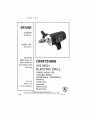
OWNERS
MANUAL
MODEL NOr
315,1041-1
CAUTION:
Read Rules for
Safe Operation
and Instructions
Carefully
3/8 INCH
ELECTRIC DRILL
DOUBLE
INSULATED
VARIABLE
SAVE THIS
MANUAL
FOR
FUTURE REFERENCE
ADJUSTABLE
Warranty
Introduction
SPEED
- REVERSIBLE
Operation
Maintenance
Repair
Dest ned exclusively for and sold only by
SEARS, ROEBUCK AND CO, Dept 698/73tA, Sears Tower. Chicago,
el_$17,2gY
t,4_e
®
Parts
IL 60884
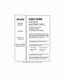
FULL ONE YEAR WARRANTY
ON CRAFTSMAN
ELECTRIC
DRILL
If this Etectdc Drill fat_s to give complete satisfaction w_thtn one year from the date of purchase
RETURN tT TO THE NEAREST SEARS SERVtCE CENTER/DEPARTMENT
THROUGHOUT THE UNITED
STATES and Sears will repair It, free of charge,
If this electric drill Is used for commercial or rental purposes this warJ:antyapptlas for only 90 days from
the date of purchase.
This warranty gives you specific tegat rights, end you may atso have other rights which vary from state
to state_
SEARS, ROEBUCK AND CO,
DEPT. 731CR,W
SEARS TOWER
CHICAGO. IL 60684
INTRODUCTION
IMPORTANT -- Servicing of a tool with double fnsu_ation requires extreme care and knowledge of the
system and should be performed cnty by e qualified
service technician. For service we suggest you
return the tool to your nearest Sears Store for repair,
Always use original factory replacement parts whoa
servicing.
DOUBLE INSULATION is a concept In safety, In elec,
trio power tools, which eliminates the need for the
usual three wire grounded power cord and grounded
supply system. Wherever there is electric current In
the tool there are two complete sets of insulation to
protect the user. Alt exposed metai parts are lsotated
Item the Internal metal motor components with pro..
tectlng InsuIatlon
RULES
FOR
SAFE
OPERATION
READ ALL INSTRUCTIONS
1_ KNOW YOUR POWER T'OOL -- Read owner's manual carefully. Learn its applications
and limitations
as weft as the specific potential hazards related to
this tool.,
2, GUARD AGAINST ELECTRICAL SHOCK BY PREVENTING BODY CONTACT
WITH GROUNDED SURFACES_ For example: Pipes, radiators, ranges, refrigerator enclosures.
3, KEEP GUARDS IN PLACE and in working order.
4 KEEP WORK AREA CLEAN, Cluttered areas and benches Invite accidents.
5, AVOID DANGEROUS
ENVIRONMENT.
Don't use power tool in damp or wet
locations or expose to rain_ Keep work area well lit.
6_ KEEP CHILDREN AWAY. Atl visitors should wear safety glasses and be kept
a safe distance from work area. Do not let visitors contact tool or extension
cord.
7_ STORE IDLE TOOLS. When not in use, tools should be stored In a dry, high or
locked-up place -- out of the reach of children,
8 DON'T FORCE TOOL It will do the Job better and safer at the rate for which it
was designed.
9 USE RiGRT TOOL. Don't force small tool or attachment to do the job of a heavy
duty tool Don't use toot for purpose not intended - for example - Don t use
a clrcutar saw for cutting tree limbs or logs=
10 WEAR PROPER APPAREL. No loose clothing or Jeweiry to get caught In moving
parts. Rubber gloves and non.skid footwear are recommended
when working
outdoors, AJso, wear protective hair covering to contain long hair
11, USE SAFETY GLASSES with all toots. Also face or dust mask if operation Is
dusty_
Page 2
RULES FOR SAFE OPERATION
12
13.
!4,
t5,
16
17
18,
19,
20_
21+
22_
23+
24
25+
26
27,
28+
29
30.
3t
32
33
(Continued)
DON'T ABUSE CORD, Never carry tool by cord or yank it to disconnect from
receptacle.
Keep cord from heat, oi!, and sharp edges.
SECURE WORK+ Use clamps or a vise to hold work, Both hands are needed to
operate the tool
DON'T OVERREACH. Keep proper footing and balance at all times+ Do not use
on a ladder or unstable support,
•
MAINTAIN TOOLS WITH CARE,, Keep tools sharp at all ttmes, and clean for best
and safest performance
Fotlow instructions
for lubricating and chang+rig accessories,
DISCONNECT TOOLS. When not in use, before servicing, or when changing attachments, blades, bits, cutters, etc, all tools should be disconnected
from
ower supply.
REMOVE ADJUSTING KEYS AND WRENCHES. Form habit of checking to see
that keys and adjusting wrenches are removed from toot before turning it on
AVOID ACCIDENTAL STARTING,, Don't carry plugged+in toots with f_nger on
switch. Be sure switch is off when plugging in+
OUTDOOR USE EXTENSION CORDS, When tool is used outdoors, use only
extension cords suitable for use outdoors
Outdoor approved cords are marked
wtth the suffix W.A for example -- SJTW-A or SJOW+A+
KEEP BITS CLEAN AND SHARP+ Sharp bits minimize stalling and klckbac_
KEEP HANDS AWAY FROM DRILLING AREA,, Keep hands away from bits Do
not reach underneath
work white b_t is rotating- Do not attempt to remove
material while bit is rotating,
NEVER USE IN AN EXPLOSIVE ATMOSPHERE.
Normal sparking of the motor
could tgnlte fumes.
INSPECT TOOL CORDS PERIODICALLY
and if damaged, have repaired at your
nearest Sears Repair Center.
INSPECT EXTENSION CORDS PERIODICALLY and replace tf damaged,
KEEP HANDLES DRY, CLEAN, AND FREE FROM OIL AND GREASE. Always
use a clean cloth when cleaning. Never use brake fluids, gasoline, petroleumbased products or any strong solvents to clean your toot,
STAY ALERT. Watch what you are doing and use common sense Do not op,
erate tool when you are tired,, Do not rush
CHECK DAMAGED PARTS,, Before further use of the toot, a guard or other part
that ts damaged should be carefully checked to determine that It witl operate
properly and perform its intended function,
Check for alignment of moving
parts, binding of moving parts, breakage of parts, mounting, and any other
conditions
that may affect its operation
A guard or other part that is damaged
should beproperly
repaired or replaced by an authorized service center,
DO NOT USE TOOL IF SWITCH DOES NOTTURN IT ON AND OFF,, Have defect,
ire switches replaced by an authorized service center.
DRILLING INTO ELECTRICAL WIRING IN WALLS CAN CAUSE DRILL BIT AND
CHUCK TO BECOME ELECTRICALLY
LIVE. Do not touch the chuck or metal
houslng when drilling into a wail; grasp only the Insulated handle(s) provided on
the tool.,
Inspect for and remove al! naits from lumber before drilling.
DRUGS, ALCOHOL, MEDICATION,
Do not operate tool while under the influence of drugs atcohol, or any medication
WEAR HEARING PROTECT ON DUR NG EXTENDED PERIODS OF OPERA.
TION.
SAVE THESE INSTRUCTIONS,
Refer to them frequently
and use them to
instruct third party users ff you loan someone this toot, loan them these
Instructions also,
PagB 3
OPERATION
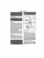
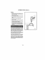
KNOW YOUR DRILL
Before attempting
to use your drill,
familiarize
yourself with all operat ng leatures and safety re
quirements. See Figure 1.
AUXILIARY HANDLE
CHUCK
"XX"x4
CAP SCREW
Make sure power supply is t10o120 veils, 60 Hz, AC
only.
REVERSIBLE
Your ddit has the feature of being reversible, The
direction of chuck rotafion Is controlled by a lever
located above the trigger sw_loh, See Figure 1. With
drill held In normal operating position, the direction
of rotatton lever should be positioned to the right of
the switch for drilling The dd}l direction fe reversed
When the iever ts to the left of the switch, THE
DESIGN OF THE SWITCH WILL NOT PERMIT
CHANGING
DIRECTION
OF ROTATION WHILE
DRILL IS RUNNING. RELEASE THE SWITCH TRIGGER AND ALLOW THE DRILL TO STOP BEFORE
CHANGING iTS DIRECTION, NOTE: YOUR DRILL
WILL NOT RUN UNLESS THE SWITCH LEVER IS
PUSHED FULLY TO LEFT TO RIGHT.
INSTALLING AUXIUARY HANDLE
An auxtUary handle is packed with your drill for ease
of operation and to help prevent loss of control To
Instal_, Insert the hex head cap screw through the
handle, Using a screwdriver, push on the head of the
cap screw in order to seat tt Into the molded portion
of the handie. Next, start the threads Into the thread..
ed hole In the gear housing and tighten securely See
Figure I,
LOCK-ON SWITCH
The switch of your drUl is equipped w_th a "lock.on"
feature for added ut]ltty and convenience when drill,,
lng In soft woods or soft metaSs, To lock-on, depress
the trigger of the switch, push in the lock button
located on the side of the hendte, then while h01dlng
the look button pushed in, release the trigger. To
release the took, depress the tdgger and release tt
LOCK-ON
VARIABLE SPEED
CONTROL SELECTOR
DECREASE SPEED
TO INCREASE
SPEED
Fig. 1
VARIABLE SPEED
Your drill has a variable speed control, selector
deslgned to allow operator central of speed and torque tlmits See Figure 1, To Increase the speed and
torque of your drift, hold your dill! tn normal
operating position and turn the variable speed conh
trol seteotor clockwfee. Turn counterclockwise
to
decrease the speed and torque of your drill If you
desire to lock the switch on at a given speed, pull the
trigger of the.switch, push In the lock button located
on the side of the handle, then while holding the Iock
button pushed In release the Irlgger, Next, adjust the
varlabte speed control selector until the desired
speed is reached. NOTE: IF THE VARIABLE SPEED
CONTROL SELECTOR IS FULLY TURNED IN THE
COUNTERCLOCKWISE
DIRECTION
{ZERO SET.
TTNG), YOUR DRILL MAY NOT RUN.
IF YOU DESIRE NOT TO USE THE VARIABLE SPEED
CONTROL
SELECTOR, TURN IT IN THE FULL
CLOCKWISE DIRECTION, THIS WILL ALLOW THE
SPEED OF YOUR DRtLL TO BE FULLY CONTROLL.
ED BY THE AMOUNT
OF SWITCH TRIGGER
DEPRESSION=
Page 4
OPERATION
The following
guidelines
may be used in determining
LOW speed Is ideal when minimum
punching, mixing paint, and drltllng
MEDIUM speed }s suitable
(Cont.)
correct
speed !or varioes applications:
speed and power is required
in ceramics
For example:
starting
holes withe_t
center
for drilling hard metals, plastfcs, and laminates
HIGH speed produces best results when maximum power is required For example: drllttng in wood; soft metals
such as aluminum, brass, and copper; and when using driving accessories
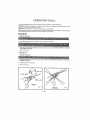
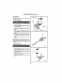
INSTALLING BITS
See Figures 2 & 3
1 UNPLUG YOUR DRILL,
2, loser
di'tll bit into chuck the lull length ol the jaws as shown in Figure 2,
3 Using the chuck key provided, tighten chuck jaws secureiy on drill bit, DO NOT USE A WRENCH TO TIGHTEN
OR LOOSEN THE CHUCK.
4
Remove chuck key
REMOVING
BITS
1 UNPLUG YOUR DRILL
_i..
;_ I _
,J I _o
I
_i
2 {tslr_g the chuck key provided, loosen
LOOSEN THE CHUCK,
= "
..........'W:_[HI,
IliI=I_IIIL,_ -l'llr:_tltll_'| ''. ' ' !
chuck Jev,,e from drill bll
DO NOT USE A WRENCH
'
TO TIGHTEN OR
3 Remove drill b!f lrom chuck jaws
4 Remove chuck key
DRILL
BIT
CHUCK
CHUCK JAWS
RIGHT
Fig 2
WRONG
Page 5
Fig 3
OPERATION
(Cont.)
DRILLING
See Ftgure 4
1
Depress and release the sWitch trigger to be sure
your drill Is in the "Off" posttton before connec
ring it to power supply
2.
Check the direction of rotation
setting (forward or reverse}
3
Secure the material to be drtlted in a vlse or with
clamps to keep It from turning as the ddtl btt
rotates
4
P_ug your drill into power supply source
5
Hold your drlil firmly
point to be drilled
6
Depress the switch trtgger to start your drill. Do
not lock the switch "On" for Jobs where the drltl
may need to be stopped suddenly,
7
Move the drltr bit into lhe workp{ece applying on..
ty enough pressure to keep the bit cutting, Do
not force your drill or apply side pressure to
elongate a hole Let your drill
and bit do the work
See Figure 4
lever for correct
and piece (he bit at the
When drilling hard smooth surfaces use a center
punch to mark the desired hole legation. This wit]
prevent the drtl! bit from slipping off center as the
hole Is started, However, the variable speed feature
allows starting
holes without center punching
if
desired. To accomplish
this, simply operate your
ddtl at a low speed until the hote _s started
When drtltlng metals use a light oil on the drill bit to
keep it from overheating. The ofl will prolong the life
of the bit and increase the drtIilng action
If the bit Jams In the workplace or If your drill stalls,
stop the tool Immediately. Remove the bit from the
workplace and determine the reason for Jamming
Avoid running your drill at low speeds for extended
periods of time At lower speeds under constant
usage, your dritt may become overheated. If this oc.,
curs, operate dr_ll without a load and at full speed to
cool It mote qulckty
Page 6
Ftg 4
OPERATION
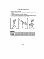
CHUCK REMOVAL
See Figures 5, 6 & 7
(Cont.)
PiN OR NAIL
The chuck must be removed in order to use some accessories To remove:
!
UNPLUG YOUR DRILL,
CHUCK
2
Cfose the chuck Jaws
3.
Line up hole in spindle with hole In gear housing
and insert s 1t8 Inch diameter nail or pin into
hole tn spindle shaft
4.
Insert chuck key into chuck and tap sharply with
a mailer In a clockwise direction as shown In
Figure 5
5.
Open the chuck laws and remove the chuck
screw by turning tl In a clockwise direction. See
Figure 6. NOTE: The chuck screw has left hand
threads
6.
Insert chuck key in chuck and tap sharply In a
counterclockwise direction to loosen it on spin,.
die, It can now be unscrewed by hand See
F/gum Z
7
Unlock spindle by removing
housing
MALLET
CHUCK KEY
Fig 5
nail or pln from gear
The chuck may at tlmes become loose on the spin..
die and develop a wobble, Also, the chuck screw
may become loose causing the chuck jaws to bind
and prevent them from clostng To tighten, follow
these steps;
t
UNPLUG YOUR DRILL
Fig 6
2
Open the chuck Jaws.
3
Line up ho!e in spindle with hole In gear houslng
and insert s 1/B Inch diameter halt or pin Into
hole In spindle shaft
4
insert chuck key in chuck and tap with a matlet In
a clockwtse direction
5. Tighten the chuck screw. NOTE: The chuck
screw has left hand threads
6
Unlock sp]ndte by removing nail or p_n from gear
houstng
Fig 7
Page 7
OPERATION
CRAFTSMAN
CHUCK
KEY
by forcing
HOLDER
1
Form
a loop
Figure 8,
2,
Place
the
3.
Mount
in the
the chuck
key by insetting
larger
hote, smaller
keys
loop
over
the
(Cont.)
end
with
round
cord
and
putl
holes
it tight.
the geared
in the small
through
See
Figure
slotted
hole
or_ opposite
end
See
Large
keys
9
end through
the hole
hole. See Figure
10,
in the holder,
CORD
CHUCK KEY
HOLDER
Fig. 8
Fig 9
0
CHUCK KEY
The operation of any Dtlll can result in foreign objects being thrown Into your eyes, which
can result tn severe eye damage. Before commencing power tool operation, always wear
safety goggles or safety glasses with side shields and e lust lace shield when needed. We
recommend Wide Vision Safety Mask for use over spectacles or standard salary glasses
with side shields, evaltebEe at Sears Catalog Order or Retail Stores.
Page 8
MAINTENANCE
GENERAL
Only the parts shown on parts list, page eleven, are
Intended to be repaired or replaced by the customer_
All other parts represent an Important pad of the
double Insulation system and should be serviced on.,
ty by a qualified aervtce technician
Avoid using solvenla when cleaning pIasllc parts.
Most plastics are susceptible to various types of
commercial solvents and may be damaged by their
use Use clean cloths to remove did, carbon dust,
etc
When etectr$c toots are used On fiberglass boats,
sports cars, etc., it has been found that they are subJect to accelerated wear and possible premature
failure as the fiberglass chips and grlndlnga are
highly abrasive to bearings, brushes, commutator,
etc. Consequently 11Is not recommended that this
toot be used for extended work on any fiberglass
materiel. During any usa on fiberglass tt Is extremely
important that the tool is cleaned frequently by blow..
Ing with an air Jet. ALWAYS WEAR SAFETY' COG.
GLES OR SAFETY GLASSES WITH SIDE SHIELDS
BEFORE BEGINNING POWER TOOL OPERATION
OR BLOWING DUST.
EXTENSION CORDS
The use of any extension cord wtll cause some loss
of power_ To keep the toss to a mfntmum and to pro,
vent tool overheating, foIlow the recommended cord
sizes on the chart below. When tool Is used out,,
doors, use only extension cords sultabte for outdoor
Use and so marked, Extension cords are available at
Sears Catalog Order or Reiall Stores
Extension Cord Lenglh
25..50 Feet
50-75 Feet
75-100 Feet
THE FOLLOWING RECOMMENDED
MANUAL WAS PRINTED..
Wire Size AW.G.
lB
16
14
LUBRICATION
All the bearings in this tooi are lubricated with a suf.
tlctent amount of high grade lubricant for the life of
the unit
under
normal
operating
condit!ons,
therefore, no further lubrication ls required
ACCESSORIES ARE CURRENT AND WERE AVAILABLE AT THE TIME THiS
High Speed Bits (For wood or metaI)
Masonry Bits
Wood Boring Bffs
Hole Saws
Hole Square (99 2595)
Carrying Case (9 1477}
The use of attachments
3/8"
1 t2"
!-1t4'
lq/2'"
Max
Max.
Max
Max
Drill Stand (9 25989)
Dowe_lng Jig {9 4186)
Cord Lock (9. 2595)
Chuck Key Holder (99 2978)
Portallgn OrilI Guide (9 11227)
Wood Boring Pilot Set {9 2588)
or accessories not listed above might be hazardous
Page 9
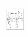
CRAFTSMAN
3/8 INCH ELECTRIC
DRILL -- MODEL NUMBER
3!5.10411
1
10
NOTE "'A"PAGE 11
4
2
\
5
3
12
19 18
\
\
20
17
16
15
11
CRA_
._IAN
3/8
INCH
ELECTRIC
DRILL
--
MODEL
NUMBER
315.10411
1
Always mention the Model Number in all correspondence
regarding your
The
Number willDRILL
be found
on aofdaring
pla_,eattached
the Motor Housm 9. t
3/8 Model
INCH ELECTRIC
or when
repair to
parts.
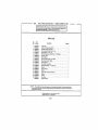
PARTS LIST
Key
No.
PaH
Number
1
6t2121-001
2
3
989490.001
98946_064
4
989479-095
5
617966.017
6
7
621635-061
829994-000
8
614927-003
9
622943-000
10
623262-600
11
616476-003
12
8t7515-001
t3
!4
617595-004
612909-001
15
623338-000
16
931655-814
17
98948_Q01
t8
19
931055-802
607122-002
20
990108-001
612547-207
Description
Quantity
Logo Plate ..................................................
SIeeve and Bearing Assembly .................................
Spindle and Gear Assembty ...................................
Gear Housing (includes Key No, 15).............................
*Screws (#8-10 x 1-1/4" T.F.) ....................................
Ball Bearing (Hoover 77R6M1AC4) "*STD315065 ..................
Retaining Rtng ..............................................
Chuck Spacer ...............................................
Chuck Key Holder(Cat.
No. 9 2978) .............................
Chuck Key (Cat, No. 9 205B) ....................................
*Screw (Special) ..............................................
Chuck (Cat, No. 9 29?5) .......................................
* Cap Screw (//3/824 x 1-1t2 He× Hd,) ............................
Handle .....................................................
Sleeve Bearing ..............................................
Washer ....................................................
Cluster Gear and Shaft Assembty ..............................
Washer ....................................................
Bee_ing ....................................................
Date Plate ..................................................
Owner's Manuel
NOTE: "A"
-- Thu _esembly
shown
cation or dam=go Io Ihe System,
Calelog
Offfe_r or _ole|]
Store.
represents
_n |mportanl
pa_l at Iho Double Insulated
serv_
_,h_uld be performed
by your nesrest
Seers
"St=ndl_'d
"*Ayaltable
Hlrdwttra
Item -- MI_/ee
Purche_ed
F_'om Qhr, S8 -- S_urCe 9BO, CO
Page
tt
SV_IOm, TO _vcrld the
Rept=It _n_r,
Conl_tcl
Lo_-_lly
1
1
1
1
4
1
1
t
I
1
1
1
!
1
t
1
I
1
t
t
po_s|bll|ly
o| o||erYour nee_'eet S_rs
3/8 INCH
ELECTRIC DRILL
OWNERS
MANUAL
DOUBLE
INSULATED
VARIABLE
SPEED
ADJ USTABLE- REVESl BLE
SERVICE
MODEL NO.
315.10411
Now that you have purchased your Eleatrlc Drfll0
should a need ever exist for repair parts or service,
.simply contact any Sears Service Center and most
Sears, Roebuck and Co. stores. Be sure to provide
all pertinent facts when you call or visit.
The mode! number of your' Eiectrtc Drill will be found
on the plate attached to the motor housing,
HOW TO ORDER
REPAIR
PARTS
WHEN ORDERING REPAIR PARTS, ALWAYS
THE FOLLOWING INFORMATION:
•
PART NUMBER
• PART DESCRIPTION
•
MODEL NUMBER
315.10411
= NAME OF ITEM
Electric Dr]lt
GIVE
All parts listed may be ordered from any Sears Service Center and most Sears stores.
If the parts you need are not stocked locally, your
order wtlt be electronically
transmitted
to a Sears
Repair Parts Distribution
Center for handling.
SEARS, ROEBUCK AND CO,
Sears Tower, Chicago, IL 60884