1
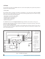
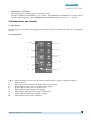
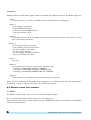
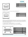
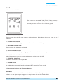
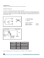
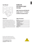
CHLORIDE
POWER PROTECTION
INDEX
1.0 Scope ........................................................................... 2
2.0 System description ..................................................... 3
3.0 General requirements ................................................ 6
4.0 Battery management ................................................... 6
5.0 Monitoring and control .............................................. 7
6.0 Remote alarms and controls ...................................... 8
7.0 Technical data ............................................................. 11
8.0 Options ...................................................................... 13
MKA4ST0UKPLAN5-7/Power Lan/ed.5/09-2003/UK
1
1.0 SCOPE
This specification describes the POWER LAN series of static uninterruptible power systems and presents its
electrical and mechanical features.
1.1 The system
An increasing number of machines are sensitive to disturbances on the mains power supply. The POWER
LAN series of static Uninterruptible power systems shall provide high quality AC power for electronic equipment loads and shall offer the following features:
• Improvement in the power supply quality
• Compatibility with every type of load
• Protection against power failures
• Intelligent battery management
• Very low running costs.
The POWER LAN series offers Digital Interactive design architecture with minimum running costs.
Single-board digital technology now allows a high level of integration of components, allowing a reduced footprint and increased reliability (MTBF).
The use of latest technology power transistors, with switching times of 20 kHz, reduces circuit noise to
extremely low levels at any power rating, and ensures perfect output wave characteristics irrespective of the
type of loads being powered.
------- Monitoring and
dialogue lines
---------
Power lines
1 - Mains phase
2 - Mains neutral
3 - RS232 link
4 - Dedicated
shutdown link
5 - Static by-pass
6 - Output phase
7 - Output neutral
8 - Filter
9 - Microprocessor
chip
10 - Remote signalling
and controls
11 - Manual by-pass
Figure 1. POWER LAN Diagram
2
MKA4ST0UKPLAN5-7/Power Lan/ed.5/09-2003/UK
CHLORIDE
POWER PROTECTION
1.2 Models available
The POWER LAN series shall include models with Single-phase input and Single-phase output as specified in
the following table under normal conditions:
MODELS
Power
(kVA) @ 25°C
POWER LAN 5 230 V
5
POWER LAN 7 230 V
7
2.0 SYSTEM
Input
Output
Single-phase
Single-phase
Single-phase
Single-phase
DESCRIPTION
POWER LAN is the result of an innovative Research and Development programme designed to offer users
the most reliable power supply at minimum cost.
2.1 Components
•
•
•
•
•
•
A charger, which converts alternate current from the mains into direct current for charging the
batteries
Batteries, which power the UPS when the mains power fails.
An inverter, which converts direct current from the batteries into sinusoidal alternate current in a
form which can be used by the sensitive loads. This ensures a very stable output voltage and frequency.
A static by-pass, auxiliary circuit which maintains the power of the loads in the case of inverter failure
or overload.
A manual by-pass, which permits on-line maintenance without disconnecting your load.
Monitoring and shutdown software with the ability, via RS-232 port to monitor UPS functioning and
programme POWER LAN parameters in order to provide optimum performance, and many other
features.
2.2 Microprocessor control and diagnostics
POWER LAN series operation and control shall be provided through the use of microprocessor controlled logic.
The coloured LEDs on the front panel of POWER LAN series shall provide a simple and immediate indication
of the operational state of the UPS.
For a more detailed and complete description on local diagnostics, see section 8 (options).
2.3 Modes of operation
In normal operation, from the instant measurement of output voltage, the microprocessor continuously
calculates the correct value of output voltage and initiates the corresponding step to keep output voltage
within the accepted tolerances.
The front mains led is On indicating that the mains is within voltage and frequency tolerances and the output
led is ON, showing that POWER LAN is supplying the load.
The charger charges the batteries and maintains them in charged state.
The microprocessor controls the charger voltage according to the internal temperature value of POWER
LAN, in order that the batteries are charged at the correct voltage for a specific temperature, thus prolonging
battery life.
MKA4ST0UKPLAN5-7/Power Lan/ed.5/09-2003/UK
3
The charger limits the voltage absorbed by the batteries. This allows an optimal charge cycle for batteries since
there will be an initial period in which batteries are charged with constant voltage (and their voltage increase)
and a second period in which the voltage is constant (value of floating) and the voltage decreases.
When the charger current is above a threshold value, the front battery led will be ON showing that batteries
are recharging.
When the charger current is lower than this value, the battery led will be OFF, indicating that the batteries are
charged. If the battery led is blinking, the batteries are in floating condition because the charger current is
around the threshold value.
The microprocessor regulates fan speed according to the output current. At any moment, the enforced bypass can be executed.
By-pass led will turn red indicating that the load is supplied by the static by-pass and in the event of any
problem with the mains this will be transferred to the load.
While POWER LAN is working normally, several events can happen:
2.3.1 Output Overload
If the value of MAXIMUM CURRENT OUTPUT is exceeded, the buzzer, by-pass led and alarm led will activate;
fans will take their maximum speed and, after a while, if there is overheating, POWER LAN will stop, cut the
output and reset the alarms.
It will be necessary to start it up again through the On push button or using the software. If the overcharge
disappears before the POWER LAN shuts down, the alarms will be reset and POWER LAN will keep on
working normally.
If output current is between 38 and 50A, POWER LAN will stop after 60 seconds. If it is between 50 and 60A
it will stop after 15 seconds. Between 60 and 65A it will stop in 7 seconds and if over 65A, it will stop in 4
seconds.
2.3.2 Temperature Alarm
In the event of the internal temperature of POWER LAN being higher than the value of MAXIMUM INTERNAL
TEMPERATURE the alarms will be activated.
2.3.3 Protection of Overheating
If any component of POWER LAN reaches the value defined as MAXIMUM TEMPERATURE OF INVERTER5ºC, the alarm will be activated. To deactivate it, the temperature should be reduced under MAXIMUM
TEMPERATURE OF INVERTER -10ºC.
If the temperature keeps on rising and reaches the value of MAXIMUM TEMPERATURE OF INVERTER,
POWER LAN stops completely and cuts the output.
To restart POWER LAN, you must press the On push button or do it through software.
2.3.4 Battery Overvoltage
If battery voltage is higher than the value of MAXIMUM VOLTAGE OF BATTERIES the charger stops and the
alarms are activated.
4
MKA4ST0UKPLAN5-7/Power Lan/ed.5/09-2003/UK
CHLORIDE
POWER PROTECTION
2.3.5 Mains Failure
If mains is out of voltage or frequency tolerances, POWER LAN will transfer to batteries.
At that moment, the charger stops and the inverter is activated (which was synchronized to mains) and
batteries start to discharge.
The result is that the load continues to be supplied by the inverter.
The front mains led switches off, the alarm led is switched on and the alarms are activated.
When mains returns to its normal values and provided that there is no battery cut-off, the inverter synchronizes
to mains, the inverter stops, the charger starts up, the alarms are reset, the alarm led is Off and the mains led
is switched on.
During battery discharge the inverter may stop because it is not allowed to discharge the batteries.
There are several areas which do not allow the discharging of batteries:
2.3.5.1 Auto-Off
If POWER LAN is operating from batteries and for a period of 30 seconds the output current is less
than the value of MINIMUM THRESHOLD and provided that the option AUTO-OFF is activated, POWER
LAN will stop the inverter and cut the output and go into stand-by mode.
2.3.5.2 Authorized autonomy
When the AUTHORIZED AUTONOMY is finished, POWER LAN stops the inverter, cuts the output
and gets into stand-by mode.
2.3.5.3 Empty Batteries
When battery voltage gets down to 10V/Bat, POWER LAN stops the inverter to avoid battery damage
and goes into stand-by mode.
If, after completing the battery isolation, mains returns before the stand-by time finishes, POWER LAN will
start automatically provided that the stop keys have not been pressed. In that case it will not start. If you want
to start it up, you must press the front push button or do it through software.
2.3.6 Standby Working
The unit is in standby when, in the absence of mains, the unit is stopped.
In this mode the internal circuits are using battery power. POWER LAN can communicate and keep its internal
clock.
The power supply of internal circuits will stop if battery voltage decreases under a minimum value of voltage
(11V/Bat) or when the STAND-BY time is finished. At that moment, POWER LAN stops completely, there is
not any possibility of communication, the internal clock stops and any consumption of battery power is arrested.
To restart POWER LAN, it is necessary to restore the mains and push the front push button or activate it
through software.
MKA4ST0UKPLAN5-7/Power Lan/ed.5/09-2003/UK
5
3.0 GENERAL
REQUIREMENTS
3.1 Standards
CHLORIDE Power Protection is certified by the British Standard Institution (BSI) as a company with a total
quality control system in accordance with ISO9001.
POWER LAN series is designed and manufactured in accordance with the following international standards:
EN50091-1
EN50091-2 class B
IEC950
3.2 Components and materials
All materials and parts comprising the UPS shall be new and in current production, and to ensure maximum
reliability, they shall be used well within the parameters recommended by the supplier.
4.0 BATTERY
MANAGEMENT
Using advanced battery care POWER LAN series shall increase the battery life by up to 30%. The main
battery care features shall include:
4.1 Ambient temperature compensated battery charger
To ensure optimum recharging of the battery, the floating voltage is automatically adjusted as a function of
ambient temperature (-0.1% per °C).
4.2 Autonomies
Autonomy is the length of time that the UPS can supply a load when a mains failure occurs, that is, when the
UPS takes energy from batteries.
POWER LAN has the possibility of activating an autonomy learning period through a dialog program. This
means POWER LAN supplies the load taking energy from the batteries until these are discharged and records
the time. This time will be stored internally as LEARNT AUTONOMY.
The learning training of autonomy must be completed with the batteries fully charged and with the user’s
typical load. In this way, the user will know which is his POWER LAN autonomy with his usual load.
In addition to LEARNT AUTONOMY, there are 3 further autonomy functions:
•
POSSIBLE AUTONOMY.
During the discharge of batteries it is the value of the LEARNT AUTONOMY minus the already elapsed
autonomy minutes.
Example: if the LEARNT AUTONOMY is 15 minutes, there is a mains failure and POWER LAN starts
discharging batteries, after 2 minutes of discharging, the POSSIBLE AUTONOMY will be 15 minus 2=13
minutes.
•
AUTHORIZED AUTONOMY
It is the maximum time allowed to discharge batteries in a discharge. If there is a mains failure and
POWER LAN changes to batteries, they will only discharge for a maximum time fixed by the value of
AUTHORIZED AUTONOMY although the batteries have more energy to keep on discharging. This
allows the maintenance of energy in the batteries in the case of any subsequent mains failure.
6
MKA4ST0UKPLAN5-7/Power Lan/ed.5/09-2003/UK
CHLORIDE
POWER PROTECTION
•
REMAINING AUTONOMY
This represents the remaining time to the battery cut off.
Example: If LEARNT AUTONOMY is 15 minutes, AUTHORIZED AUTONOMY 10 minutes, after 3
minutes of discharging, the value of REMAINING AUTONOMY will be 10 minus 3 = 7 minutes.
5.0 MONITORING
AND CONTROL
5.1 Introduction
By employing microprocessor technology, the UPS shall provide an advanced and easy to use diagnostic
system.
5.2 Control panel
1
3
4
8
7
9
10
2
6
1&2
3
4
5
6
7
8
9
10
-
5
Switch off buttons: both must be pushed simultaneously to prevent accidental shutdown.
Start-up button.
Alarm reset button: silences the audible alarm when pressed.
Forced by-pass button: used to activate forced by-pass.
By-pass LED: lit when unit is in by-pass mode.
Battery LED: lit when batteries are charging.
Mains LED: lit when the mains power is within limits.
Output LED: lit when output voltage is sensed.
Alarm LED: lit when a fault is detected.
MKA4ST0UKPLAN5-7/Power Lan/ed.5/09-2003/UK
7
5.3 Alarms
POWER LAN has several Buzzer signals, which are activated upon different scenarios. The Buzzer signals are:
-
Buzzer 1
1 long beep each 15 seconds. It is always activated when batteries are discharging.
-
Buzzer 2
5 short beeps. It is activated:
- when POWER LAN starts
- when you switch POWER LAN off
- when the autotest is done
-
Buzzer 3
1 long beep each second. It is activated when the low battery alarm sounds ie. when there is a short
time to the battery shut down.
-
Buzzer 4
2 short beeps which are activated:
- upon resetting of the microprocessor
- for each change of mains status
- for each step to batteries
- for each change of temperature alarm
- when a total switch off is done
-
Buzzer 5
Not used.
-
Buzzer 6
5 short beeps and a long one continuously. Activated when:
- overtaking of MAXIMUM OUTPUT CURRENT
- overtaking of MAXIMUM INTERNAL TEMPERATURE
- overtaking of MAXIMUM TEMPERATURE OF INVERTER
-
Buzzer 7
20 short beeps. It is activated when the enforced by-pass is required .
Buzzer 6 can be activated even if POWER LAN is stopped or is in stand-by mode. The rest except beep 4
provoked by a reset are only activated when the unit has been started.
6.0 REMOTE
ALARMS AND CONTROLS
6.1 RS232C
The RS-232 connector (RJ11 with 4 wires) provides the following signals:
Pin 1 is reserved and should never be used, as it is not voltage free.
This connector, used with the cable supplied with the POWER LAN, allows communication with DIALOG
software via PC serial port.
8
MKA4ST0UKPLAN5-7/Power Lan/ed.5/09-2003/UK
CHLORIDE
POWER PROTECTION
PIN
1
2
3
4
SIGNAL
Reserved (+5V @ 10mA)
TXD, transmits data to the PC
Ground
RXD; receives data from the PC
6.2 Computer interface
The Shutdown connector (RJ11 with 4 wires) provides the following signals:
PIN
1
2
3
4
SIGNAL
Low battery
Mains failure
Ground
Remote shutdown (from a PC)
This connector provides RS-232-level signals required for shutdown. The ground is common with the RS-232
connector. The remote shutdown signal (+12V) should persist for at least 2.5 seconds to be accepted. Cable
42 can be used if volt-free contacts are needed as it provides the mains failure and battery low signals through
volt-free contacts (see Options Section).
6.3 POWER CONTROL CONNECTOR (Remote control and signalling)
The POWER CONTROL connector (SUB-D 25 pin female) provides the following signals:
Pin
1
2
3
4
5
14
15
17
18
MKA4ST0UKPLAN5-7/Power Lan/ed.5/09-2003/UK
Use
Mains failure
UPS ON
Low battery
Solid-state by-pass ON
Remote shutdown
Signal sink
Ground (connected to pin 14)
Remote start-up
Outputs +15V, 100 mA
Signal
Active Closed
Active Closed
Active Closed
Active Closed
+12V
+15V
9
The MAINS FAILURE, UPS ON, LOW BATTERY and BY-PASS ON signals are open collector output signals
rated for 15 mA max. (sink).
All other points are reserved for other applications and should never be used for communications with the
computer. (They carry other voltage signals.)
The connector can be used to transmit signals for remote start-up/shutdown of the POWER LAN.
10
MKA4ST0UKPLAN5-7/Power Lan/ed.5/09-2003/UK
CHLORIDE
POWER PROTECTION
7.0 TECHNICAL
DATA
POWER. VA
Power. W
Technology
INPUT
Nominal Voltage
Input voltage windo
Frequency
OUTPUT
Nominal voltage
Voltage tolerance
Frequency variation
Power Factor
Galvanic isolation
UPS efficiency
CHARGER
Battery type
Nominal Battery voltage
Floating voltage
Number of batteries
Charger current
Temperature compensation
INVERTER
Power factor
Output wave form
Nominal voltage
Frequency
Overload
Max. Overload
Harmonic distortion (%)
Linear load
Informatics load
Static stability
Dynamic stability
50% to 100%
0% to 100%
Crest factor
FUSES
Input fuses
Battery fuses
Auxiliary output fuses
LEAK TO EARTH
PROTECTIONS
Short circuit
Overcurrent
Overtemperature
5000
3500 w
7000
4900 w
Digital On-line
Single phase
220/230/240V (Software adjustable)
+ 10% - 15%
50Hz (optional 60Hz) ±4% (synchronisation)
Single phase
220 / 230 /240V (Software adjustable)
± 5%
± 4 % working on main
± 0.1 % working on inverter
0.7
Yes
> 95 %
VRLA
144 V
163.8 V
12x12V 7 Ah
144 V
163.8 V
24x12V 7 Ah
2.5 A
Yes
0.7
Sinusoidal
220 / 230 / 240 V (Software adjustable)
50Hz (optional 60Hz) ±0.1%
200% (3 sc.) – 150% (30 sc.) – 120% (1min.)
200%
< 3%
< 5%
±1%
±2
±5
3:1
32 A
50 A
16 A
32 A
63 A
16 A
< 3 mA
Yes
Yes
Software adjustable alarm from 0 to nominal
Software adjustable alarm from 0 to 90º C
MKA4ST0UKPLAN5-7/Power Lan/ed.5/09-2003/UK
11
GENERAL
By-pass Static
By-pass Manual
Thermal dissipation
(50% Load)
(75% Load)
Output connection
Output connection switch
Transfer time to inverter
Transfer time to by-pass
ENVIRONMENT
& DIMENSIONS
Altitude
Dimensions (H x W x D)
Humidity
Acoustic noise
Weight
Ventilation
12
Yes
Yes
Yes
Yes
→ 79.2 Kcal/h
→ 118.8Kcal/h
→ 110 Kcal/h
→ 166.3 Kcal/h
Terminal
OFF Bottom
0 sc.
0 sc.
0 sc.
0 sc.
3000 m without degradation
580x260x630 mm
90%
< 50 dBA
106 Kg.
Forced
90 %
< 50 dBA
150 Kg
Forced
MKA4ST0UKPLAN5-7/Power Lan/ed.5/09-2003/UK
CHLORIDE
POWER PROTECTION
8.0 OPTIONS
8.1 Remote Control Module
The remote control module (Code 550016.001) is an accessory
that connects to the POWER LAN power control connector. It
allows remote start-up and shutdown of the UPS as well as
permitting remote monitoring of the following signals:
1 - MAINS STATUS LED
Green indicates that the UPS input voltage is within tolerances. Red indicates that mains power is out of
tolerance.
2 - BYPASS STATUS LED
Red indicates that the forced bypass is active. Green indicates normal UPS operation.
3 - BATTERY STATUS LED
Green indicates that the battery is charged.
Red indicates that the battery is low.
4 - OUTPUT STATUS LED
Green indicates that the UPS is providing output. Red indicates that there is no output.
5 - SHUTDOWN CONTROLS
Both of these buttons must be pressed simultaneously to shut down the UPS.
6 - STARTUP CONTROL
This button is pressed to start up the UPS.
7 - ALARM MUTE
Press this button to silence audible alarms generated by the remote power control unit.
An audible alarm is activated if any of the 4 status LED’s change from green to red.
8.2 International Voltages and Frequency Options
VOLTAGE:
Nominal voltage for standard UPS units is of 230 Vac and 115 Vac. Through the Monitoring and shutdown
software you can adjust output voltage in the range between 220 and 240 Vac, for 230 V.
MKA4ST0UKPLAN5-7/Power Lan/ed.5/09-2003/UK
13
FREQUENCIES:
In addition to the standard 50 Hz models, there are 60 Hz variants.
8.3 Volt Free Contact Kit
This option is composed of cable 42, Part number: 279100.000
It connects to the RS-232 and shutdown connectors through the RS-232 IN and SHUTDOWN-IN inputs.
It will return the signals received from the POWER LAN through its RS-232 OUT and SHUTDOWN OUT.
In addition, the volt-free contact connector provides MAINS FAILURE and LOW BATTERY signals isolated as
shown in figure below.
1 - Low battery signal
8 - Mains failure signal
7 - Signal sink
Contact specifications:
Maximum voltage:
Maximum amperage:
Maximum power:
100 Vdc
0.5 A
10 W/VA
SHUTDOWN
SHUTDOWN
OUT
VOLT FREE
CONTACTS
J1
Position 1 - 2
Position 2 - 3
Signal
+10 V
-10 V
LOW BATTERY
Contact Closed
Contact Closed
J2
Position 1 - 2
Position 2 - 3
Signal
+10 V
-10 V
MAINS FAILURE
Contact Closed
Contact Closed
Up to 5 of these options (for isolated signals) can be installed in cascade configuration.
14
MKA4ST0UKPLAN5-7/Power Lan/ed.5/09-2003/UK
CHLORIDE
POWER PROTECTION
8.4 Interface Cables
Optionally, different cables can be provided for interface, shutdown and communication with computers.
These include the following:
•
•
Cable AS400
This cable allows connection to the IBM AS400 or similar systems.
MODEL 37 order code 279075.001
This is the standard cable supplied with POWER LAN and allows communication between the UPS
and Monitoring and Shutdown software. It connects to the RS-232 port on the POWER LAN and any
serial communications port (COM) on a computer.
8.5 LIFE
This option shall allow the remote monitoring of the UPS through dedicated telephone lines in order to
ensure the maximum reliability of the UPS throughout its operational life. The monitoring shall be a true 24
hour, *365 day service thanks to a unique feature that allows trained Service Engineers to be constantly in
contact electronically with the service centre and therefore the UPSs. The UPS shall automatically telephone
the service centre at defined intervals to provide detailed information that shall be analysed in order to
predict near term problems. In addition, it shall be possible to control the UPS remotely. To ensure complete
safety for the user and for the critical load, an active control device shall be utilised which disables the remote
connection when any one of the POWER LAN panels is removed for maintenance operations.
The transmission of UPS data to the CHLORIDE Service Centre shall take place via modem at the following
intervals:
• ROUTINE: typically once a week
• EMERGENCY: when a problem occurs or the operating parameters remain outside the tolerance limits
• MANUAL: upon customer’s request
• BI-DIRECTIONAL: following the request of the service centre
During the call the service centre shall:
• Identify the connected UPS.
• Recognise the type of call
• Request the data stored in the UPS memory during the time interval since the last connection
• Request real time information from the UPS (selectable)
The service centre shall analyse historical data and issue a regular detailed report to the customer informing
him of the UPS operational condition and any critical parameters.
8.6 SNMP Adapter
The SNMP (Simple Network Management Protocol) adapter shall allow the network administrator to analyse
and monitor Power Lan series from any point on the network.
The adapter is compatible with MIBII (Management Information Base) which defines the type of information
transferred between the NMS (Network Management Station) and Power Lan The NMS supported are:
HP Openview for Windows
SunNet Manager
Novell NMS
IBM Netview
The connectors available are of the BNC and RJ45 type for Ethernet networks.
8.7 Shutdown Software
This option shall allow a controlled and systematic shutdown of systems supported by both standalone and
MKA4ST0UKPLAN5-7/Power Lan/ed.5/09-2003/UK
15
networked POWER LAN series installations. For intelligent power utilisation the software shall allow the
transmission of shutdown information for the connected users. In addition, for efficient power management
the software shall offer the function of scheduling routine shutdowns through user friendly Windows interfaces. A number of options shall be offered by the software for customising the use of its various power
management features.
Monitoring and Shutdown software is included bundled with POWER LAN and the optional software will
only be required for operating systems not supported by the standard version.
8.8 Extended Battery Charger
This option shall be a Module designed in order to provide an higher recharge current thus enabling POWER
LAN series to be connected to batteries able to deliver several hours of autonomy.
8.9 MultiCom
This option will replicate the RS232 port allowing connection of up to 3 separate connectivity applications.
16
MKA4ST0UKPLAN5-7/Power Lan/ed.5/09-2003/UK