1
HMP240 SERIES
TRANSMITTERS
User's Guide
M210300en-A
June 2002
Vaisala Oyj 2002
No part of this document may be reproduced in any form or by any means,
electronic or mechanical (including photocopying), nor may its contents be
communicated to a third party without a prior written notice of the copyright
holder.
The instruction manuals may be changed without prior notice.
HMP240 series
User's guide
M210300en
Contents
1.
PRODUCT DESCRIPTION ..........................................................................................5
2.
ADVANTAGES OF A WARMED SENSOR HEAD ........................................................7
3.
INSTALLATION ..........................................................................................................8
4.
5.
3.1
Selecting the place of installation.................................................................8
3.2
Mounting ........................................................................................................9
3.2.1
Mounting the HMP243.......................................................................9
3.2.2
Mounting the HMP247..................................................................... 11
3.3
Grounding .................................................................................................... 13
3.4
Electrical connections ................................................................................. 15
3.4.1
Connection to a 24 VAC supply ....................................................... 16
COMMISSIONING..................................................................................................... 17
4.1
Changing the parameters ............................................................................ 17
4.2
Security lock jumper .................................................................................... 17
4.3
Selecting the analogue outputs .................................................................. 18
4.4
Connecting the RS 232C serial bus............................................................. 20
4.4.1
Reverting to factory settings of the serial port.................................. 22
COMMANDS ............................................................................................................. 24
5.1
Commands and security lock jumper ......................................................... 24
5.2
LED commands ............................................................................................ 25
5.3
Display/keypad commands .......................................................................... 26
5.3.1
Display mode .................................................................................. 26
5.3.2
Command mode ............................................................................. 26
5.3.3
Entering numbers............................................................................ 26
5.3.4
Analogue output commands ............................................................ 27
5.3.4.1 Selecting the output (mA/V) ............................................................ 27
5.3.4.2 Selecting and scaling the analogue output quantities ...................... 28
5.3.5
Output via the serial bus ................................................................. 29
5.3.5.1 Turning the serial interface echo ON/OFF ....................................... 29
5.3.5.2 Serial bus settings........................................................................... 29
5.3.5.3 Setting the transmitter address ....................................................... 30
5.3.5.4 Selecting the output units ................................................................ 31
5.3.5.5 Selecting the calculation mode........................................................ 31
5.3.6
Output modes ................................................................................. 31
5.3.6.1 Setting the serial interface operation mode ..................................... 32
5.3.7
Others............................................................................................. 33
5.3.7.1 Setting the averaging time............................................................... 33
5.3.7.2 Setting the pressure for mixing ratio and wet bulb
calculations ................................................................................. 33
5.3.7.3 Setting the date............................................................................... 34
5.3.7.4 Setting the time............................................................................... 34
5.3.7.5 Heat on / heat off command ............................................................ 35
5.4
Serial commands.......................................................................................... 35
5.4.1
Analogue output commands ............................................................ 35
5.4.1.1 Setting the analogue outputs ........................................................... 35
5.4.1.2 Selecting and scaling the analogue output quantities ...................... 36
5.4.1.3 Scaling the analogue outputs .......................................................... 36
i
HMP240 series
User's guide
5.4.2
5.4.2.1
5.4.2.2
5.4.2.3
5.4.2.4
5.4.2.5
5.4.2.6
5.4.2.7
5.4.2.8
5.4.2.9
5.4.2.10
5.4.3
5.4.3.1
5.4.3.2
6.
7.
ii
M210300en
Output via the serial bus ................................................................. 36
Starting the measurement output.................................................... 36
Stopping the measurement output .................................................. 36
Outputting the reading once............................................................ 37
Setting the output interval for the RUN mode .................................. 37
Serial bus settings .......................................................................... 37
Selecting the output units ............................................................... 38
Setting the averaging time .............................................................. 38
Setting the transmitter address ....................................................... 39
Setting the calculation mode........................................................... 39
Resetting the transmitter ................................................................ 39
Operating the transmitter via the serial bus..................................... 40
Setting the serial interface .............................................................. 40
OPEN & CLOSE ............................................................................. 41
CALIBRATION ......................................................................................................... 42
6.1
Humidity calibration .................................................................................... 42
6.1.1
One point humidity calibration......................................................... 43
6.1.1.1 With serial commands .................................................................... 44
6.1.1.2 With display / keypad commands................................................... 44
6.1.1.3 With LED commands...................................................................... 45
6.1.2
Two point humidity calibration......................................................... 45
6.1.2.1 With serial commands .................................................................... 45
6.1.2.2 With display / keypad commands.................................................... 46
6.1.2.3 With LED commands...................................................................... 47
6.1.3
Humidity calibration procedure after sensor change........................ 48
6.1.3.1 With serial commands .................................................................... 48
6.1.3.2 With display / keypad commands.................................................... 48
6.1.3.3 With LED commands...................................................................... 49
6.1.4
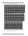
Humidity calibration table................................................................ 50
6.2
Temperature calibration .............................................................................. 50
6.2.1
One point offset calibration ............................................................. 51
6.2.1.1 With serial commands .................................................................... 51
6.2.1.2 With display / keypad commands.................................................... 51
6.2.1.3 With LED commands...................................................................... 51
6.2.2
Two point temperature calibration................................................... 52
6.2.2.1 With serial commands .................................................................... 52
6.2.2.2 With display / keypad commands.................................................... 53
6.2.2.3 With LED commands...................................................................... 53
6.3
Calibration of analogue outputs ................................................................. 54
6.3.1
With serial commands .................................................................... 54
6.3.2
With display / keypad commands.................................................... 54
6.3.3
With LED commands...................................................................... 55
MAINTENANCE........................................................................................................ 56
7.1
Reference measurements ........................................................................... 56
7.2
Self-diagnostics........................................................................................... 56
7.3
Replacing the composite sensor ................................................................ 57
7.4
Temperature channel (additional) adjustment with Pt 100 simulators ..... 57
7.4.1
With serial commands .................................................................... 58
7.4.2
With display commands.................................................................. 58
7.4.3
With LED commands...................................................................... 58
7.5
Temperature channel adjustment with Pt 100 simulators (composite sensor)
...................................................................................................................... 59
7.5.1.1 With serial commands .................................................................... 60
7.5.1.2 With display commands.................................................................. 60
HMP240 series
User's guide
M210300en
7.5.2
8.
With LED commands ...................................................................... 60
7.6
Measurement of output currents using test points.................................... 60
7.7
Adjusting the contrast of the display.......................................................... 61
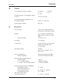
TECHNICAL DATA ................................................................................................... 62
8.1
Dewpoint temperature ................................................................................. 62
8.2
Temperature (with additional T sensor head)............................................. 63
8.3
Calculated variables .................................................................................... 63
8.3.1
Relative humidity (with additional T sensor head) ............................ 63
8.3.2
Accuracy of other calculated variables ............................................ 64
8.4
Outputs ......................................................................................................... 65
8.5
Electronics ................................................................................................... 65
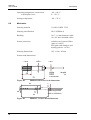
8.6
Mechanics .................................................................................................... 66
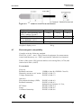
8.7
Electromagnetic compatibility..................................................................... 67
SPARE PARTS AND ACCESSORIES............................................................................... 68
APPENDIX 1: SERIAL COMMANDS ................................................................................ 69
APPENDIX 2: INSTALLING AND USING THE RS 485/422 SERIAL PORT MODULE ...... 91
APPENDIX 3: INSTALLING AND USING THE DIGITAL CURRENT LOOP MODULE .... 102
APPENDIX 4: ERROR MESSAGES ................................................................................ 110
APPENDIX 5: CALCULATION FORMULAS ................................................................... 116
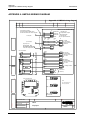
APPENDIX 6: HMP240 WIRING DIAGRAM .................................................................... 118
APPENDIX 7: RE-GAINING ............................................................................................ 119
iii
HMP240 series
User's guide
This page intentionally left blank.
iv
M210300en
HMP240 series
User's Guide
M210300en
1.
PRODUCT DESCRIPTION
The HMP240 transmitter is a microprocessor based instrument for the
measurement of dewpoint temperature especially in high humidities and/or
fast changing temperatures. The dewpoint temperature is measured through
relative humidity and temperature. The dewpoint temperature, although a
calculated variable, is the primary reading obtained with the HMP240. As the
probe is equipped with the warming function, the relative humidity reading
obtained is not correct as such whereas the dewpoint temperature is. If the
temperature is below 0 °C, the user can select whether the transmitter
calculates dewpoint or frostpoint reading; as default, the transmitter calculates
frostpoint.
The transmitter can be ordered with one or two sensor heads. If the transmitter
has only a humidity sensor head, it can output the dewpoint temperature or the
mixing ratio. If the transmitter is ordered with an additional temperature head,
the user can choose the output from the following readings: dewpoint, relative
humidity, ambient temperature, dewpoint difference (= ambient temperature dewpoint), mixing ratio, absolute humidity, and wet bulb temperature. The
configuration that the user completes in the order form determines the
available readings. The transmitter has two analogue outputs and can be
connected to a serial bus via the RS 232C interface or through an RS 485/422
serial module or a digital current loop module.
There are various possibilities for the configuration of the transmitter. It can
have either a blank cover, or a cover with a local display and keypad with
which to operate the transmitter. Two analogue output signals are selected
from the measured and calculated quantities; the signals can be scaled and the
measurement ranges changed. The HMP240 can be supplied with two, five or
ten meter sensor head cables.
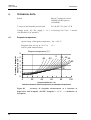
The dewpoint measurement range is -40...+100 °C. The range depends on the
desired accuracy because the dewpoint is calculated through the RH and the T
readings (see Chapter 8). The analogue temperature output can be scaled quite
freely, for example -20...+60 °C can be set to correspond to 0...10 V. The
relative humidity, absolute humidity, dewpoint difference, mixing ratio and
wet bulb temperature ranges are also scalable.
In some specific applications, the sensor gain may gradually decrease because
of an interference caused by some particular chemicals present in the ambient.
These changes can be recovered with an optional re-gaining function.
The transmitter is equipped with a composite humidity and temperature
sensor; the operation of the HUMICAP®KC humidity sensor is based on
changes in the capacitance of the sensor as its thin polymer film absorbs water
molecules.
5
HMP240
User's Guide
M210300en
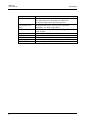
Options
Additional T probe
Calculation variables
Serial interface
Display cover
Filters
Cable lengths
Installation aids
HMP243MIK
6
For the measurement of the ambient temperature and
for obtaining other quantities in addition to
dewpoint temperature and mixing ratio
dewpoint difference, mixing ratio, absolute
humidity, wet bulb temperature
RS 232C (standard), RS 485/422, digital current
loop module
cover with local display & keypad
sintered filter, PPS grid with steel netting
2, 5 or 10 meters
Installation kit for temperatures up to 180 °C
Meteorological installation kit
HMP240 series
User's Guide
M210300en
2.
ADVANTAGES OF A WARMED SENSOR HEAD
In some measurement applications, unwanted dew formation makes humidity
measurement difficult or even impossible. At a weather station, for example,
high humidity combined with rapidly changing outdoor temperature can
condense the water vapour in the air onto the sensor head. Until this dew
evaporates or dries, it is impossible to obtain a true reading. Dew formation is
also a problem in environmental chambers and in processes involving high
humidity, such as meat processing.
In some applications, rapid temperature changes are the source of difficulty.
Normally, relative humidity sensors must be at the same temperature as the
ambient air or the measurement is incorrect. At +20 °C and 90 %RH a difference of +1 °C causes an error of +6 %RH. This makes reliable humidity
measurements difficult in rapidly changing temperatures.
In other applications, the problem is a combination of both the dew formation
and rapid changes of temperature; a rapid rise in temperature can cause a
corresponding increase of water vapour in the ambient. In these conditions, the
temperature of the sensor head rises more slowly, and can remain below the
dewpoint of the ambient for a while. Dew then forms on the sensor head, and
it may take several hours or in the worst case, several days for the sensor to
recover from the condensation.
Vaisala's HMP240 dewpoint transmitter offers a reliable solution for humidity
measurement in all these demanding conditions. The humidity sensor head is
kept dry by warming it. As the measurement is fully temperature compensated,
changes in the process temperature do not delay the measurement. This means
that the response time of dewpoint measurement is proportional only to the
diffusion time of water molecules inside the sensor head.
The HMP240 has an excellent performance also at normal humidities and in
stable environments, but it will mostly be used in applications where very high
humidity can take place. In these kinds of applications, the use of traditional
transmitters has been restricted.
7
HMP240
User's Guide
3.
INSTALLATION
3.1
Selecting the place of installation
M210300en
The transmitter should be installed in a place that gives a true picture of the
environment or process and is as clean as possible. Air should circulate freely
around the sensor. If necessary, the transmitter can be installed in a place
where a hot spot may develop. However, cold spots should be avoided.
When the sensor head is installed in a duct or a process channel where the
temperature is different from the ambient temperature, insulate the point of
entry; this is particularly important if the transmitter is installed with the
sensor head pointing downwards. Installing the sensor head of the HMP240
vertically is not recommended because in high humidities, the humidity may
condence on the sensor head cable and then flow on to the sensor head.
When there is no alternative but to install the sensor head in the process
vertically, the point of entry must be carefully insulated. The cable must also
be allowed to hang loosely in order to prevent any water that possibly
condenses on the cable from running onto the sensor head.
Install the humidity sensor head in the process wherever possible. Avoid
sample flows where the gas temperature can drop below dewpoint
temperature; this might result in erroneous measurement readings. Install the
sensor head transversely against the direction of the process flow. If the
process temperature is much higher than that of the environment, the whole
sensor head and preferably part of the cable must be inside the process.
In duct or channel installations drill a hole ready for a reference meter. Plug
the reference hole tightly (see Figure 3.2).
Install the electronics housing away from possible steams escaping from the
process.
8
HMP240 series
User's Guide
M210300en
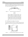
3.2
Mounting
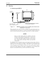
3.2.1 Mounting the HMP243
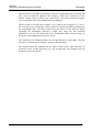
133
humidity
sensor head
T-sensor head
(optional)
104
ø6.5
Cable length 2000,
5000 or 10000 mm
Figure 3.1
Sliding PTFE-sleeve for flange installation
and cable-gland installation
HMP243 transmitter with a humidity sensor head and an
additional T sensor head
When mounted on the side of a duct or channel, the sensor head must be inserted from the side (see Figure 3.2). If this is not possible and the sensor head
must be inserted from the top, the point of entry must be carefully insulated.
NOTE
The two sensor heads should be installed so that the
humidity sensor head does not warm the T sensor head,
i.e. the T sensor head is installed closer to the process
flow. When the RH reading is required, always install
the T sensor head in the place where you need the
reading from.
The HMP243 can be installed in ducts and channels with the help of the installation kit; the kit consists of a flange, a supporting bar for the sensor head
cable and screws for attaching the flange to the wall of a duct. With the help
of the installation kit the distance between the sensor head and the channel
wall can be easily adjusted. The range of adjustment is 100...320 mm; the
distance is measured from the tip of the sensor head to the flange.
9
HMP240-series
User's Guide
M210300en
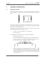
duct wall
flange
sealing (silicone)
humidity sensor head
a plugged hole for reference
measurements
supporting bar
T-sensor head
(optional)
PTFE sleeve
Figure 3.2
Installing the sensor heads of the HMP243 in a channel
with the help of flanges and supporting bars
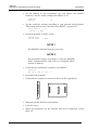
The sensor head can also be installed vertically.
PTFE-sleeve
when a bushing is used, its
size is selected according to
the diameter of the sensor
head; the diameter of the
cable is increased by using
e.g. silicon tape at the bushing
a bushing (cable-gland)
(seal:Viton)
to be sealed
(silicone)
stain
or a
stainless steel
cable tie or a
similar fastener
m
h
humidity sensor
h
head
T-sensor head
(o ptio na l)
Figure 3.3
10
Vertical installation of the HMP243 sensor heads
HMP240 series
User's Guide
M210300en
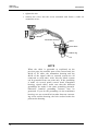
3.2.2 Mounting the HMP247
HMP247 has a small size probe made of stainless steel. The sensor head
withstands temperatures -40...180 ºC (-40...356 ºF) and pressure up to 10 bar
(1MPa, 145 psi). The probe is suitable for applications where a mechanically
very durable leak proof probe is needed.
Pressure tight installations
A pressure tight installation can be done by using a probe head installation or
cable installation. Vaisala's cable gland HMP247CG is recommended for the
humidity probe's cable installation.
The different pressure tight installations of the HMP247 are shown in the
following pictures. In cases where the probe shall be positioned horizontally in
the measuring chamber (or in duct) a supportive thread bar set HMP247TBS
can be ordered from Vaisala (order code: HMP247TBS).
A) Probe head installation
1. Make hole with M20x1.5 thread
in the measurement chamber or
process wall. The smoothness of
the thread circle should be
R= 6.3 microm.
2. Install the cable gland
(EN50262, version A, example:
AGRO 1160.20.145) on the thread
of the process wall.
Process pressure <
10 bar, temperature
according to the
cable's sealing
A) Pipe fitting
∅30/M20x1.5x13.5
3. Push the probe through the
gland so deep that the backside of
the probe is flust with the cable
gland nut.
4. Tighten the cable gland nut,
the probe will lift up slightly.
B) Cable
installation with
Vaisala's
HMP247CG
∅13.6 mm
∅ 5.3 mm
B) Cable
installation with
Vaisala's
HMP247CG
Figure 3.4 HMP247 Pressure tight installations A) Probe head installation
B) Cable installation (cable gland: HMP247CG) .
11
HMP240
User's Guide
M210300en
Pressure tight installation with Vaisala's supportive thread bar
set HMP247TBS (cable gland HMP247CG included)
1. Make a hole with M20x1.5 to a wall or weld a pipe fitting
(∅30/M20x1.5x12mm) to a wall.
2. Install the cable gland's fitting body on the hole in the wall.
3. Thread the sensor head through the nut and press the cable
through the cutting line of the sealing.
4. Turn the supporting bars into the sensor head's threaded holes.
5. Turn the sleeve on the opposite end of the supporting bar and
trim to the right length.
6. Cut away the overage supporting bar with saw.
7. Press the sleeves together (with cable inside) and install the
sensor head to a process through the fitting body.
8. Tighten the cable gland nut.
For processes up to 120°C (248 °F). More detailed
instructions are included in the set.
Cable gland
HMP247CG
Example of pressure tight temperature probe installation
(cable gland example: AGRO Nr. 1100.12.91.065, EN50262,
version A)
Process pressure < 7 bar,
temperature according to the cable
sealing
∅ 6.5 mm
Recommended support to
Silicon glue between the PTFE
keep the probe in
fitting and the cable.
horizontal position
Figure 3.5 HMP247 pressure tight installations with supporting bars.
12
HMP240 series
User's Guide
M210300en
3.3
Grounding
A single electrical cable with a screen and three to ten wires is recommended
for power and analogue output/serial bus connections. The cable diameter
should be 7...10 mm.
The screen of the electrical cable must be grounded properly to achieve best
possible EMC performance. Recommended cable shield is done in the cable
gland as shown below.
•
remove the brass disks, rubber ring and nut from the transmitter
housing
•
strip 165 mm of the cable insulation, but leave 25 mm of the braid
visible
•
slip the nut and rubber ring over the cable insulation
•
slip the brass disk that has the bigger hole in it over the braid so that
it rests against the cable insulation
•
slip the other brass disk over the wires to the middle of the braid
2
3
flexible wires 0.5 mm
(AWG 20), stranded wires
recommended
140
165
braid
shielding tube
brass
disks
braid
25
brass disks
rubber
ring
nut
cable
D = Ø 7...10 mm
(If the cable diameter is less
than 7mm, use a shrinking
tube or an adhesive tape)
•
push back the braid and press it between the two brass disks to
achieve a full 360° grounding; the fold between the disks should have
the same diameter as the brass disks
•
secure the braid with a shielding tube
•
insert the wires into the transmitter housing through the gland
13
HMP240
User's Guide
M210300en
•
tighten the nut
•
connect the wires into the screw terminals and fasten a cable tie
around the wires
cable tie
transmitter housing
gland
brass disks
rubber ring
nut
NOTE
When the cable is grounded as explained on the
previous page, the metallic parts of the sensor head, the
shield of its cable, the transmitter housing and the
shield of the signal cable to external system are all
connected to each other. After this the whole system
can be grounded from one point only. If the grounding
is made via several points (sensor head, transmitter
housing, signal cable), make sure that the different
groundings are made to the same grounding potential.
Otherwise harmful grounding currents may be
generated. If you do the grounding via the transmitter
housing, use one serrated lock washer between a mounting screw and the housing; the lock washer breaks the
paint on the housing.
14
HMP240 series
User's Guide
M210300en
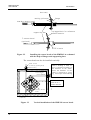
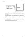
Electrical connections
CH1+
CH1CH2+
CH2-
CH1- and CH2- are connected
together internally
+
+
V
mA
V
mA
-
CURRENT/VOLTAGE
OUTPUTS
-
POWER SUPPLY
24 V +
3.4
Do not use power supply
ground (-) as output signal
ground
X2
X1
OPENED COVER OF THE HMP 243
Figure 3.6
Electrical connections
Power supply
24 VDC
24 VAC (see Chapter 3.4.1)
Output signals
0...20 mA
4...20 mA
0...1 V
0...5 V
0...10 V
Power supply ground (-) is connected to the housing with parallel connection
of 15 nF capacitor and 300 kΩ resistor.
15
HMP240
User's Guide
M210300en
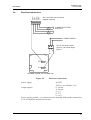
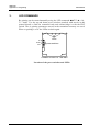
3.4.1
Connection to a 24 VAC supply
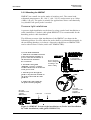
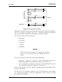
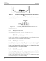
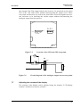
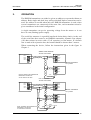
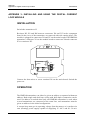
The HMP240 transmitter can also be connected to a 24 VAC supply without
an external rectifier. However, when more than one transmitter is connected to
one 24 VAC transformer, a common loop is formed and there is an increased
risk of a short-circuit. To avoid this, always use separate floating supply for
each transmitter (see Figure 3.7 A). However, if several transmitters have to
share one transformer, the phase (∼) must always be connected to + connector
in each transmitter (see Figure Figure 3.7 B).
A) NO COMMON LOOP FORMED - RECOMMENDED
signal output
signal output
24 VAC
supply voltage
24 VAC
supply voltage
HMP243 transmitter
Controller
HMP243 transmitter
B) COMMON LOOP FORMED - NOT RECOMMENDED!
signal output
Controller
shared
common line
signal output
supply voltage
24 VAC
supply voltage
HMP243 transmitter
HMP243 transmitter
Figure 3.7
16
Connecting the transmitters to a 24 VAC supply (valid
also for the HMP247 transmitter).
HMP240 series
User's Guide
M210300en
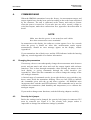
4.
COMMISSIONING
When the HMP240 transmitter leaves the factory, its measurement ranges and
output signals have already been scaled according to the order form completed
by the customer. The unit is calibrated at the factory and ready to operate
when the power is turned on. If you take into use active current, voltage or
serial bus outputs, make these connections first; appendix 6 describes them in
detail.
NOTE
Make sure that the power is not turned on until cables
have been connected to screw terminals!
In transmitters with display, the software version appears for a few seconds
when the power is turned on. After this, measurement results appear
automatically. Should an error message appear on the display, consult
Appendix 4.
If your transmitter has a blank cover and the LED indicator inside the housing
lights up, consult Appendix 4 for further information.
4.1
Changing the parameters
If necessary, the user can subsequently change the measurement units between
metric and non-metric and select and scale the output signals with software
functions. This is done through commands, either utilizing the menus on the
local display or giving commands through the serial interface (see
Appendices). Most often the commands are used to change the settings of the
two analogue channels.
A limited range of commands can be given with the three press switches (up,
down, enter) inside the transmitter housing. There are four LEDs to indicate
the commands given with the up and down switches. All HMP240 units
incorporate these switches and LED indicators. LED commands can be used to
calibrate the transmitters (both humidity and temperature) or to calibrate the
analogue outputs.
If you need to change some functions, read the following chapters carefully.
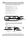
4.2
Security lock jumper
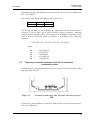
Before the settings can be changed, the security lock jumper in connector X15
must be removed (see Figure 4.1). The security lock jumper makes it
impossible to change the transmitter settings by mistake.
17
HMP240
User's Guide
M210300en
X15
CHANGE OF SETTINGS
DISABLED
OPENED COVER OF THE HMP 243
Figure 4.1
Location of the security lock jumper
When the security lock jumper is connected, some commands are not available
(see Chapter 5).
Should the application require variables that are not included in the
configuration of the transmitter, the user is invited to contact Vaisala or a
Vaisala representative.
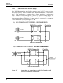
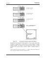
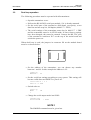
4.3
Selecting the analogue outputs
The HMP240 transmitter can be ordered ready with the current or voltage
outputs required. If the outputs need to be changed, move the jumpers in connector X15 into positions as shown in Figure 4.2.
18
HMP240 series
User's Guide
CH1
CH2
M210300en
CH1
CH2
CH1
CH2
CURRENT OUTPUTS
0 ... 20 / 4 ... 20 mA
CH1
CH2
CH1
CH2
VOLTAGE OUTPUTS
0 ... 5 V / 0 ... 10 V
CH1
CH2
CH1
CH2
VOLTAGE OUTPUTS
0 ... 1 V
CH1
CH2
CH1 0 ... 1 VOLTAGE OUTPUT
CH2 CURRENT OUTPUT
X15
OPENED COVER OF THE HMP 243
Figure 4.2
Selecting the analogue outputs with jumpers
The software has to be informed which outputs are in use. This is done either
through the serial interface or the menus on a local display. The serial
command is AMODE and the display/keypad command "Mode ð Analog
outputs ð Mode" (see Chapter 5). For the scaling of the outputs, see serial
command ASCL and the display command "Mode ð Analog outputs ð
Scale".
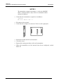
All the jumpers are used only with the 0...1 V outputs. When other outputs are
in use, the spare jumpers are kept in connector X55.
19
HMP240
User's Guide
M210300en
X55
spare jumpers
OPENED COVER OF THE HMP 243
Figure 4.3
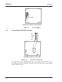
4.4
Spare jumpers
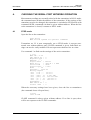
Connecting the RS 232C serial bus
RX
GND
TX
NC
X6
OPENED COVER OF THE HMP 243
Figure 4.4
Serial bus connections
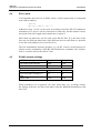
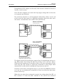
To connect a PC to the HMP240 transmitter via the RS 232C serial bus, one of
the following cables is required. The type of the cable depends on the terminal
and the connector type.
20
HMP240 series
User's Guide
M210300en
D9S
PC
2
5
3
4
6
7
8
3
7
2
D25S
5
6
8
20
TERMINAL
3
D25P 7
2
TXD
RXD
TXD
RXD
TXD
RXD
TX
GND
RX
TX
GND
RX
HMP 243
TX
GND
RX
Figure 4.5 Connection of cables
When the serial bus has been connected between the PC and the transmitter,
the PC is switched on. When using a PC, a terminal emulation programme
(e.g. Procomm Plus, Datastorm or Windows terminal) is started.
The factory settings for data transfer are:
•
4800 baud
•
even parity
•
7 data bits
•
1 stop bit
•
full duplex
NOTE
When the serial bus settings are changed, the transmitter has to be reset before the new settings become effective.
The processor does not allow the following combinations:
•
no parity, 7 data bits, 1 stop bit: if this combination is given the
HMP240 programme will change the number of stop bits to 2
•
even or odd parity, 8 data bits, 2 stop bits: if this combination is given
the programme changes the number of stop bits to 1
Refer to the manuals of the PC and the terminal emulation programme when
giving serial settings.
The RS 232C screw terminal cannot be used if an RS 485/422 serial module
or a current loop module is used. See Appendices 2 and 3 on how to install
and operate these modules.
21
HMP240
User's Guide
M210300en
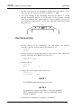
In calibrating or changing the settings of the transmitter it can be more convenient to use the connector X17, if connector X6 is already in use. This connector, however, transfers only RS 232C signals. If an RS 485/422 serial port
module or a current loop module has been installed, it has to be removed before communicating through the X17 connector.
RX GND TX
X17
Figure 4.6
Location and connections of connector X17
NOTE
Some PC computers can generate interferences to the
measured humidity and temperature values if the
transmitter and the PC are connected to different mains
outlets. To minimize the possibility of these interferences, always use the same mains outlet (same phase of
the mains electricity) for the PC and the power supply
of HMP240. This is especially the case when using the
serial line connector X17. The serial line connector X6
is more immune to these interferences than connector
X17.
4.4.1 Reverting to factory settings of the serial port
If the serial port settings are not known, no commands can be given via the
serial interface. The settings can be reverted to the factory settings by inserting
a jumper in connector X16. The jumper must be inserted when the power is
on!
X16
OPENED COVER OF THE HMP 243
Figure 4.7
22
Forcing the serial port settings back to factory settings
HMP240 series
User's Guide
M210300en
When the jumper is inserted the serial line factory settings become valid, but
only temporarily. The transmitter must be given new settings; otherwise
the transmitter uses the old, unknown settings after power-up. When the
new settings have been given, the transmitter must be reset. The jumper must
be removed before the transmitter is reset; if the jumper is in place when
power is turned on, the transmitter does not work.
After jumper insertion the transmitter is in STOP mode, ready to receive
commands.
The same method is used when the transmitter is in POLL mode and the user
has forgotten its address.
CAUTION
Inserting a jumper in any other place in connector X16
voids the guarantee of the transmitter.
23
HMP240
User's Guide
5.
M210300en
COMMANDS
As the HMP240 transmitter is a microprocessor based device, its configuration
can be set to correspond to the specific needs of the user. This is done through
commands, either by utilizing the menus on the local display or by giving
commands through the serial interface (see Appendix 1). Most often the
commands are used to change the settings of the two analogue channels.
A limited range of commands can be given by using the three press switches up, down and enter - inside the transmitter housing. Four LEDs indicate the
command given with the up and down switches. LED commands can be used
to calibrate the transmitter (both humidity and temperature) or to calibrate the
analogue outputs.
A full range of commands can be given through the display/keypad or through
the RS 232C serial bus. The commands can be used e.g. to select and scale the
outputs, to calibrate the humidity and temperature channels as well as the
analogue outputs and to set the serial interface.
5.1
Commands and security lock jumper
In order to prevent any tampering with the transmitter settings, the transmitter
cannot be calibrated, the analogue outputs set or the analogue output
quantities selected or scaled unless the security lock jumper has been disconnected. The commands involved are:
•
all LED commands
•
display/keypad commands:
•
Cali
ð
Mode
ð
RH
T Ta
Analog outputs
Analog outputs
More
More
ð
ð
More
Frost
ð
ð
Mode
Scale
Frost
serial commands:
CRH, CT, CTA, FCRH, ACAL; AMODE, ASEL, ASCL, FROST,
FILT
In the following, the description of these functions is preceded with a reminder of the security lock jumper:
Disconnect the security lock jumper!
24
HMP240 series
User's Guide
M210300en
5.2
LED commands
NOTE
If the transmitter has a display/keypad cover, the LED
commands cannot be used.
LED commands can be used to operate the transmitter in the field. These
commands can be used in humidity and temperature calibration and calibration
of the analogue outputs.
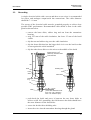
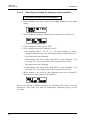
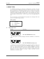
Open the housing and press any one of the three press switches. The LEDs
will light up for 2 - 3 seconds.
UP
DOWN
LEDs
press switches
ENT
OPENED COVER OF THE HMP 243
Figure 5.1
Location of press switches and LEDs
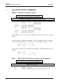
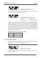
Use the up and down switches (marked with arrows on the printed board) to
find the desired command code and acknowledge it with the ENT switch. The
command codes are (l = lit, ¡ = dark):
¡¡¡¡
¡¡¡l
¡¡l¡
(0)
(1)
(2)
¡l¡¡
¡¡ll
l¡¡¡
(3)
(4)
(8)
return to normal state
relative humidity calibration
temperature calibration of the humidity sensor
head
temperature calibration of the T sensor head
calibration of analogue outputs
relative humidity calibration after sensor change
25
HMP240
User's Guide
5.3
M210300en
Display/keypad commands
5.3.1 Display mode
In the display mode the transmitter outputs measurements on the display; different quantities can be scrolled with arrow keys. The first line is scrolled with
button σ and the second line with button τ; all selections are stored with
ENTER. The selected quantities appear on the display also after power failure.
After reset the transmitter is always in the display mode.
The display also shows error messages and alarms if they occur.
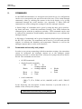
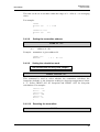
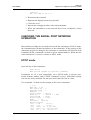
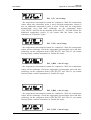
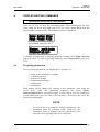
5.3.2 Command mode
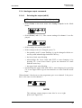
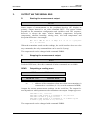
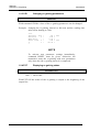
Press the CL key to enter the command mode. The first display is the main
menu:
The commands can be scrolled with the arrow keys. The currently active
command flashes; a command is selected with the ENT key. When a menu is
displayed, either the first command or the currently valid setting flashes. The
CL key takes the transmitter back to the display mode.
5.3.3 Entering numbers
When numbers need to be entered into the transmitter programme (e.g. when
scaling or setting the analogue outputs, in calibration or when giving the
transmitter an address), the field is either empty or the currently valid figure is
displayed. Any previously given value is deleted with the CL key.
When the field is empty, a cursor blinks on the right side of the display.
Pressing the arrow keys makes either a blank ' ', a comma ',', a dash '-', a full
stop '.' or a number from '0' to '9' appear on the display. The right character is
selected with ENT; after that the number or numbers move left one step.
Entering numbers is ended with selecting a blank ' ' and pressing ENT. The
last character entered can be deleted with CL. If CL or ENT key is pressed
when the field is empty, the programme returns to the previous display.
With some commands (e.g. calibration) the figures are changed using the arrow keys. When an arrow key is pressed continuously for a while, the numbers
start changing at an increasing rate.
26
HMP240 series
User's Guide
M210300en
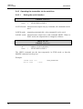
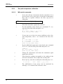
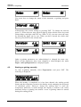
5.3.4 Analogue output commands
5.3.4.1
Selecting the output (mA/V)
Disconnect the security lock jumper!
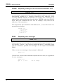
•
Select Mode in the main menu and Analog outputs in the Mode
menu:
•
Select Mode ( mA / V ). The current settings for channel 1 are displayed:
•
If the settings are correct, press ENT.
•
If the settings need to be changed, press CL:
− the quantity (mA/V) starts flashing; it can be changed with the arrow keys and acknowledged with the ENT key
− the lower limit starts flashing
− acknowledge the lower limit
with ENT or start changing it by
pressing CL; a new lower limit is given one character at a time
with the arrow keys
− the upper limit starts flashing
•
acknowledge the upper limit with ENT or start changing it by pressing
CL; a new upper limit is given one character at a time with the arrow
keys
When channel 1 has been set, the programme goes on to channel 2; the procedure is the same as with channel 1.
NOTE
The analogue output jumpers must also be set to right
places (see Figure 4.2).
27
HMP240
User's Guide
M210300en
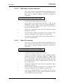
5.3.4.2
Selecting and scaling the analogue output quantities
Disconnect the security lock jumper!
•
Select Mode in the main menu and Analog outputs in the Mode
menu:
•
Select Scale. The quantity and scaling for channel 1 are displayed:
•
If the settings are correct, press ENT.
•
If the settings need to be changed, press CL:
− the
quantity (RH, T, Td, dT, x, a, Tw) starts flashing; it can be
changed with the arrow keys and acknowledged with the ENT key
− the lower limit starts flashing
− acknowledge the lower limit
with ENT or start changing it by
pressing CL; a new lower limit is given with the arrow keys
− the upper limit starts flashing
− acknowledge the upper limit
with ENT or start changing it by
pressing CL; a new upper limit is given with the arrow keys
•
When channel 1 has been set, the programme goes on to channel 2;
the procedure is the same as with channel 1.
Please note that the available selections are affected by the choice of output
parameters. Also make sure that the temperature measuring ranges are not
exceeded.
28
HMP240 series
User's Guide
M210300en
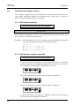
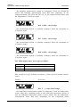
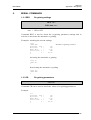
5.3.5 Output via the serial bus
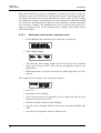
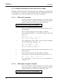
5.3.5.1
Turning the serial interface echo ON/OFF
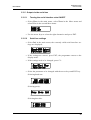
•
Select More in the main menu, select More in the More menu and
select Echo in the second More menu.
•
Use the arrow keys to select the right alternative and press ENT.
5.3.5.2
Serial bus settings
•
Select Seri in the main menu; the currently valid serial interface settings are displayed:
•
If the settings are correct, press ENT; the programme returns to the
display mode.
•
If the settings need to be changed, press CL:
•
Select the parameter to be changed with the arrow keys and ENT key.
Selecting baud rate:
Selecting parity:
Selecting data bits:
29
HMP240
User's Guide
M210300en
Selecting stop bits:
Full duplex/half duplex:
The processor does not allow the following combinations:
•
no parity, 7 data bits, 1 stop bit: if this combination is given the
HMP240 programme will change the number of stop bits to 2
•
even or odd parity, 8 data bits, 2 stop bits: if this combination is given
the programme changes the number of stop bits to 1
NOTE
The serial bus settings become effective only after reset.
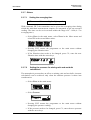
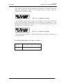
5.3.5.3
Setting the transmitter address
Address is used when more than one transmitter is connected to one serial bus;
this way, it is possible to communicate with one transmitter at a time.
30
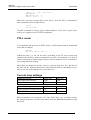
•
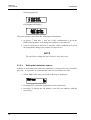
Select Addr in the main menu; the following is displayed:
•
Pressing ENT returns the programme to the main menu.
•
Pressing CL deletes the old address; enter the new address with the
arrow keys.
HMP240 series
User's Guide
M210300en
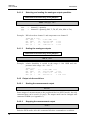
5.3.5.4
Selecting the output units
•
Select Unit in the main menu:
•
Use the arrow keys to select the right alternative and press ENT.
RH
T
Td
dT
a
x
Tw
5.3.5.5
metric
%RH
°C
°C
°C
g/m3
g/kg
°C
non-metric
%RH
°F
°F
°F
gr/ft3
gr/lb
°F
Selecting the calculation mode
Disconnect the security lock jumper!
•
Select More and then again More in the second menu:
•
Select Frost and then the desired alternative with the arrow keys;
FROST ON (default) for frostpoint and FROST OFF for dewpoint
calculation at dewpoint temperatures below 0 °C.
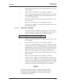
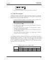
5.3.6 Output modes
The output modes only affect output through the serial interface: the transmitter accepts all display and LED commands irrespective of which serial output
mode it is in. The HMP240 transmitter has three serial output modes: RUN,
STOP and POLL.
In the RUN mode the transmitter outputs measurements automatically through
the serial interface to a PC or a peripheral. The only command that can be
given through the serial interface is S (stop), which ends the RUN mode.
In the STOP mode serial commands are given to the transmitter. Measurements are then output only by entering command SEND.
The POLL mode is used when more than one transmitter is connected to the
same serial bus; a single transmitter can be addressed and communicated with.
31
HMP240
User's Guide
M210300en
When the connection to a given transmitter is opened in the POLL mode, the
transmitter goes into STOP mode and can then receive commands normally.
Closing the connection returns the transmitter to POLL mode. In POLL mode,
the transmitter outputs measurement only when requested (command SEND
aa). If the user has forgotten the address of the transmitter and the transmitter
does not have a display, the transmitter has to be reverted to the factory settings (see Chapter 4.4.1). If the transmitter has a display, the settings can be
checked through it.
5.3.6.1
Setting the serial interface operation mode
•
Select Mode in the main menu; the following is displayed:
•
Select Serial output:
•
The currently valid setting flashes. Select the desired mode with the
arrow keys and press ENT. After this the programme returns to the
Mode Menu.
•
When Run mode is selected, the currently valid output interval is displayed:
The output interval setting can be changed as follows:
32
•
press CL
•
the number starts flashing
•
if the interval needs to be changed, press CL again and enter the new
interval; otherwise press ENT
•
the unit (seconds or hours) starts flashing
•
the unit can be changed with the arrow keys and acknowledged with
ENT
•
after this the programme returns to Mode menu
HMP240 series
User's Guide
M210300en
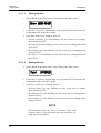
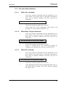
5.3.7 Others
5.3.7.1
Setting the averaging time
Disconnect the security lock jumper!
With command FILT the transmitter can be given the averaging time during
which the individual measurement samples are integrated to get an averaged
reading. The time can be set in seconds within the range of 0 - 1024 (0 = no
averaging time).
•
Select More in the main menu, select More in the More menu and
select Filt in the second More menu:
•
Pressing ENT returns the programme to the main menu without
changing the filtration time.
•
If the filtration time needs to be changed, press CL; enter the new
filtration time with the arrow keys.
5.3.7.2
Setting the pressure for mixing ratio and wet bulb
calculations
The atmospheric pressure has an effect on mixing ratio and wet bulb. Accurate
calculations can be achieved only when the ambient pressure is taken into
consideration.
•
Select More in the main menu:
•
Select Pressure:
•
Pressing ENT returns the programme to the main menu without
changing the pressure reading.
•
If the pressure needs to be changed, press CL; enter the new pressure
with the arrow keys
33
HMP240
User's Guide
M210300en
5.3.7.3
Setting the date
•
Select More in the main menu; select Date in the More menu:
•
If the date is correct, acknowledge it by pressing ENT; this takes the
programme back to the More menu.
•
If the date needs to be changed, press CL.
− first the centuries (19) start flashing; use the arrow keys to change
them and press ENT
− the years (92) start flashing; use the arrow keys to change them and
press ENT
− the months (06) start flashing; use the arrow keys to change them
and press ENT
− the days (17) start flashing; use the arrow keys to change them and
press ENT
5.3.7.4
Setting the time
•
Select More in the main menu; select Time in the More menu:
•
If the time is correct, acknowledge it by pressing ENT; this takes the
programme back to the More menu.
•
If the time needs to be changed, press CL.
− first
the hours (14) start flashing; use the arrow keys to change
them and press ENT
− the minutes (25) start flashing; use the arrow keys to change them
and press ENT
− the seconds (32) start flashing; use the arrow keys to change them
and press ENT
NOTE
The transmitter does not have a real-time clock with
backup battery. This means that the date and time settings are not permanent.
34
HMP240 series
User's Guide
M210300en
5.3.7.5
Heat on / heat off command
The status of this command should always be HEAT ON, and it should not be
altered. It is meant for service purposes only.
5.4
Serial commands
All available serial commands are described in more detail in Appendix 1. The
following chapters include only the most commonly used command
sequences. See Chapter 4.4 for connecting the HMP240 transmitter to a serial
bus.
Pressing ESC always interrupts any serial command being given. In the commands <cr> stands for carriage return.
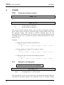
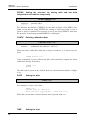
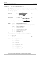
5.4.1 Analogue output commands
5.4.1.1
Setting the analogue outputs
Disconnect the security lock jumper!
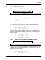
AMODE a bb.bbb cc.ccc d ee.eee ff.fff <cr>
a
=
bb.bbb =
cc.ccc =
d
=
ee.eee =
ff.fff
=
channel 1:
U = voltage output
I = current output
lower limit of channel 1
upper limit of channel 1
channel 2:
U = voltage output
I = current output
lower limit of channel 2
upper limit of channel 2
The bb.bbb, cc.ccc, ee.eee and ff.fff parameters are entered in volts or milliamperes.
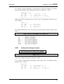
Example: lower limit of channel 1 is 0 V and upper limit 1 V
lower limit of channel 2 is 2 V and upper limit 10 V
(U 0 1)
(U 2 10)
>AMODE U 0 1 U 2 10 <cr>
Ch1 : 0.000 ...
1.000 V
Ch2 : 2.000 ... 10.000 V
35
HMP240
User's Guide
M210300en
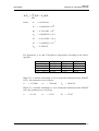
5.4.1.2
Selecting and scaling the analogue output quantities
Disconnect the security lock jumper!
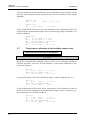
ASEL xxx yyy <cr>
xxx
yyy
=
=
channel 1's quantity
channel 2's quantity (RH, T, Td, dT, Abs, Mix or Tw)
Example: RH selected on channel 1 and temperature on channel 2
>ASEL RH T <cr>
Ch1 (RH)
lo
Ch1 (RH)
hi
Ch2 (T )
lo
Ch2 (T )
hi
5.4.1.3
0.000 %RH? <cr>
100.000 %RH
? <cr>
-40.000 'C
? <cr>
+160.000 'C
? <cr>
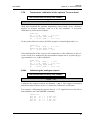
Scaling the analogue outputs
Disconnect the security lock jumper!
ASCL <cr>
Example: relative humidity is scaled in the range 0...100 %RH and temperature in the range -40...+160 °C
>ASCL <cr>
Ch1 (RH)
Ch1 (RH)
Ch2 (T )
Ch2 (T )
lo
hi
lo
hi
0.000 %RH? <cr>
100.000 %RH
? <cr>
0.000 'C ? -40 <cr>
100.000 'C
? 160 <cr>
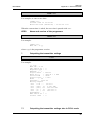
5.4.2 Output via the serial bus
5.4.2.1
Starting the measurement output
R <cr>
Starts output of measurements to the peripheral devices (RUN mode); the only
command that can be used is S (stop). The output mode can be changed with
command FORM (see Appendix 1).
5.4.2.2
Stopping the measurement output
S<cr>
Ends the RUN mode; after this command all other commands are available.
36
HMP240 series
User's Guide
M210300en
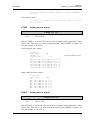
5.4.2.3
Outputting the reading once
SEND <cr> in STOP mode
or
SEND aa <cr>
aa =
in POLL mode
address of the transmitter when more than one transmitter
is connected to a serial bus (0...99)
The output format depends on which parameters the transmitter can output.
Output types:
"Td=999.9 'C", <cr><lf>
"RH=999.9 %RH T=999.9 'C Td=9999.9 'C",<cr><lf>
"Td=999.9 x=999.9 g/kg",<cr><lf>
"RH=999.9 %RH T=999.9 'C Td=9999.9 'C a=9999.9 g/m3
x=9999.9 g/kg Tw=999.9 'C",<cr><lf>
The output mode can be changed with command FORM (see Appendix 1).
5.4.2.4
Setting the output interval for the RUN mode
INTV xxx yyy <cr>
xxx
=
yyy
=
output interval (0...255)
(0 = no pause between outputs)
unit (s, min or h)
Example: output interval is changed into 10 minutes
>INTV 10 min <cr>
Output intrv. : 10 min
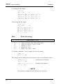
5.4.2.5
Serial bus settings
SERI b p d s x <cr>
b
p
d
s
x
=
=
=
=
=
bauds (300, 600, 1200, 2400, 4800, 9600)
parity (n = none, e = even, o = odd)
data bits (7 or 8)
stop bits (1 or 2)
duplex (H = half, F = full)
The settings can be changed one parameter at a time or all parameters at once:
37
HMP240
User's Guide
M210300en
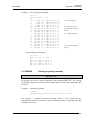
>SERI O <cr>
4800 O 7 1 HDX
changing parity only
>SERI 600 N 8 1 F <cr>
600 N 8 1 FDX
changing all parameters
The processor does not allow the following combinations:
•
no parity, 7 data bits, 1 stop bit: if this combination is given the
HMP240 programme will change the number of stop bits to 2
•
even or odd parity, 8 data bits, 2 stop bits: if this combination is given
the programme changes the number of stop bits to 1
NOTE
The serial bus settings become effective only after reset.
When the half-duplex mode is set, it will automatically turn the echo off. Even
then the ECHO command can indicate that echo is on.
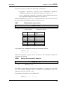
5.4.2.6
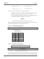
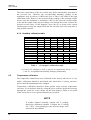
Selecting the output units
UNIT x <cr>
x =
m(etric units)
n(on-metric units)
RH
T
Td
dT
a
x
Tw
5.4.2.7
metric
%RH
°C
°C
°C
g/m3
g/kg
°C
non-metric
%RH
°F
°F
°F
gr/ft3
gr/lb
°F
Setting the averaging time
Disconnect the security lock jumper!
FILT nnnn <cr>
nnn
=
averaging time (0 - 1024 seconds)
This command is used to set and inspect the averaging time during which the
individual measurement samples are integrated to get an averaged reading.
38
HMP240 series
User's Guide
M210300en
The time can be set in seconds within the range of 0 - 1024 (0 = no averaging
time).
For example:
>FILT
Filter (S):
>
0 ?
1024
>FILT 100 <cr>
Filter (S):
100
>
5.4.2.8
Setting the transmitter address
ADDR aa <cr>
aa =
address (0...99)
Example: transmitter is given address 99
>ADDR <cr>
Address
5.4.2.9
: 2 ?
99 <cr>
Setting the calculation mode
Disconnect the security lock jumper!
FROST ON/OFF <cr>
This command is used to select whether the transmitter calculates the
frostpoint (default) or the dewpoint reading at dewpoint temperatures below
0 °C. Select FROST ON for frostpoint and FROST OFF for dewpoint
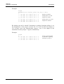
calculations. For example:
>Frost <cr>
Frost : ON
>Frost off
Frost : OFF
>Frost on
Frost : on
>
5.4.2.10
Resetting the transmitter
RESET <cr>
39
HMP240
User's Guide
M210300en
5.4.3 Operating the transmitter via the serial bus
5.4.3.1
Setting the serial interface
SMODE xxxx<cr>
xxxx
=
STOP, RUN or POLL
In STOP mode: measurements output only by command, all commands can be
used
In RUN mode: outputting automatically, only command S can be used
In POLL mode: measurements output only with command SEND. When in
POLL mode, the output mode is changed as follows:
OPEN aa <cr>
SMODE xxxx<cr>
aa
xxxx
=
=
address of the transmitter
STOP, RUN or POLL
The OPEN command sets the bus temporarily in STOP mode so that the
SMODE command can be given.
Example:
>SMODE STOP <cr>
Serial mode
: STOP
40
setting STOP mode
HMP240 series
User's Guide
M210300en
5.4.3.2
OPEN & CLOSE
OPEN nn <cr>
nn
=
address of the transmitter (0...99)
CLOSE <cr>
In STOP mode: command OPEN has no effect, CLOSE sets the transmitter in
POLL mode
In POLL mode: command OPEN sets the transmitter temporarily in STOP
mode, command CLOSE returns the instrument to POLL
mode
Example: relative humidity calibration is performed at transmitter 2 which is
in POLL mode
>OPEN 2 <cr>
>CRH <cr>
...
>CLOSE <cr>
opens the line to transmitter 2
calibration started
line closed
41
HMP240
User's Guide
6.
M210300en
CALIBRATION
The HMP240 transmitter has been fully calibrated at the factory so there
should be no immediate need for recalibration. The transmitter should be
calibrated only if there is reason to believe that the adjustments of the
transmitter have changed. The adjustments of the temperature measurement
channel and the analogue outputs are particularly stable; in normal
circumstances there is no need to recalibrate them. Humidity calibration
should be performed at least once a year.
NOTE
During the calibration procedure, the HMP240 is like
any standard RH transmitter and is therefore calibrated
against known RH values. The warming function is not
active and corrective calculations are not made. It is
therefore essential that the sensor head is allowed
enough time to stabilize to the ambient conditions in
order to ensure the highest possible accuracy in
calibration.
Either a one-point or a two-point calibration is possible. The security lock
jumper has to be disconnected at the moment of taking the transmitter to the
calibration room in order to make sure that the temperature of the sensor head
stabilizes correctly and the warming function does not interfere with the
stabilization. The stabilization of the humidity sensor head can be monitored
by the RH reading or by the T reading: the T reading is actually that of the
humidity sensor head stabilizing to the ambient temperature.
When the security lock jumper is disconnected, the serial port and analogue
outputs show the RH reading and T reading measured directly from the
humidity sensor head (instead of the calculated values). This means that the
readings (RH, T, a, x, dT or Tw) are erroneous until the humidity sensor head
has stabilized to the ambient temperature; the Td reading is correct also during
stabilization. It is recommended that the transmitter is disconnected from the
process during the calibration.
6.1
Humidity calibration
The calibration of the HMP240 transmitter can be checked with a calibrated
Vaisala humidity meter, e.g. the HM34. The HMI38 humidity data processor
with an appropriate reference connection cable can be used as a field calibrator. A two-point calibration can be done with the HMK15 or the HMK13B
calibrator, or the instrument can be sent to Vaisala. We recommend
recalibration at least once a year. The instruments must be recalibrated every
time the HUMICAPHC sensor is changed.
42
HMP240 series
User's Guide
M210300en
A ∅ 13.5 mm adapter must be used when calibrating with the HMK13B
calibrator. The adapter (part no. 16611) can be ordered from Vaisala or
Vaisala representatives.
Calibration can be performed by giving the commands with the press switches
inside the housing (see Chapter 5.2), through the serial bus (see Chapter 5.4)
or through the menus on the local display (see Chapter 5.3).
When LED commands are used and when the two analogue channels do not
output either relative humidity and/or temperature, relative humidity is calibrated on channel 1 and temperature is calibrated on channel 2. The calibration ranges are 0...100 %RH and -20...+80 °C. When the transmitters are calibrated at two points, the points must be either 50 %RH or 50 °C apart from
each other.
NOTE
If the transmitter includes the re-gaining option, the
sensor re-gaining must always be done before humidity
calibration. Before starting the calibration make sure
that the temperature of the composite sensor has come
down to ambient temperature (see Appendix 7).
6.1.1 One point humidity calibration
The HMI38 humidity data processor can be used as a one-point field calibrator. A two-point calibration with the HMI38 can also be done, provided that
two separate humidity points with a difference of more than 50%RH between
them are available. The HMI38 is connected to an HMP240 transmitter using
an appropriate reference connection cable. The necessary correction factors
are automatically stored in the HMP240 memory. Detailed calibration
instructions are given in the HMI38 operating manual.
A manual one-point correction can also be done in the field against an accurate reference.
NOTE
If the sensor has been changed, the calibration has to be
done according to the instructions in Chapter 6.1.3.
43
HMP240
User's Guide
M210300en
6.1.1.1
•
With serial commands
Make sure that the sensors of the transmitter and the
reference instrument are close to each other. Allow enough
time for the sensor heads to stabilize to the measurement
conditions
Disconnect the security lock jumper!
•
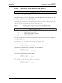
Give command CRH <cr>, enter the humidity value and
press <cr>.
>CRH <cr>
RH : xx.x
Ref1 ? yy.y <cr>
Press any key when ready...
•
If you want to see how the sensor stabilizes to the reference humidity, enter c <cr> instead of the first reference:
RH : 11.9 Ref1 ?
RH : 11.5 Ref1 ?
RH : 11.5 Ref1 ?
Press any key when
•
Press any key and <cr> when the transmitter requests the
second point value.
RH
6.1.1.2
•
c <cr>
c <cr>
11.3 <cr>
ready...
:
yy.y
Ref2 ?
<cr>
With display / keypad commands
Make sure that the sensors of the transmitter and the
reference instrument are close to each other. Allow enough
time for the sensor heads to stabilize to the measurement
conditions
Disconnect the security lock jumper!
•
44
Select Cali in the main menu and then RH cal; select Not
changed and then one-point offset correction RH 1 point
cal. Change the humidity reading with the arrow keys to
correspond to the reference value and acknowledge it with
ENT; pressing an arrow once changes the reading by 0.05
%RH.
HMP240 series
User's Guide
M210300en
6.1.1.3
With LED commands
•
Make sure that the sensors of the transmitter and the
reference instrument are close to each other. Allow enough
time for the sensor heads to stabilize to the measurement
conditions
Disconnect the security lock jumper!
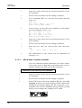
•
Connect an ammeter/voltmeter to the analogue outputs
(connector X2); if the outputs are already connected e.g. to
a process computer and you do not want to disconnect
them, the current output can be measured at separate test
points located next to connector X15 (see Chapter 7.1).
Give command ¡¡¡l (see Chapter 5.2). At the first
calibration point the LED on the left flashes; adjust the humidity point (offset) with the arrow switches to the reference value. One push of a switch changes the output by
0.05 %RH; the change of the output voltage or current depends on the output scaling. Press ENT switch. The second
LED from left starts flashing; press ENT again.
NOTE
If neither channel normally outputs the RH reading,
during the calibration channel 1 outputs the RH reading
0...100%RH, corresponding to the current/voltage scale
selected for this channel.
6.1.2 Two point humidity calibration
A two-point humidity calibration should be performed in stable conditions
using saturated salt solutions as a reference. Read also the calibrator manual.
NOTE
If the sensor has been changed, the calibration has to be
done according to the instructions in Chapter 6.1.3.
6.1.2.1
With serial commands
•
Leave the calibrator and the transmitter for at least 4 hours
in the same space so that their temperatures have time to
equalize. Remove the filter cap on the transmitter.
Disconnect the security lock jumper!
45
HMP240
User's Guide
M210300en
•
Insert the sensor head into the measurement hole of the
LiCl chamber.
•
Wait at least 10 minutes for the reading to stabilize.
•
Give command CRH <cr>, enter the first point value and
press <cr>.
>CRH <cr>
RH : xx.x
Ref1 ? yy.y <cr>
Press any key when ready...
•
If you want to see how the sensor stabilizes to the humidity in the calibrator, enter c <cr>:
RH : 11.9 Ref1 ?
RH : 11.5 Ref1 ?
RH : 11.5 Ref1 ?
Press any key when
•
Insert the sensor head into the measurement hole of the
NaCl chamber.
•
Wait at least 20 minutes for the reading to stabilize.
•
Press any key, enter the second point value and press
<cr>.
RH
•
6.1.2.2
•
c <cr>
c <cr>
11.3 <cr>
ready...
:
xx.x
Ref2 ?
yy.y <cr>
The stabilization of the sensor can be monitored by
entering c<cr>.
With display / keypad commands
Leave the calibrator and the transmitter for at least 4 hours
in the same space so that their temperatures have time to
equalize. Remove the filter cap on the transmitter.
Disconnect the security lock jumper!
46
•
Insert the sensor head into the measurement hole of the
LiCl chamber.
•
Wait at least 20 minutes for the reading to stabilize.
•
Select Cali in the main menu and then RH cal; select Not
changed and then two-point calibration RH 2 point cal.
Change the first point reading with the arrow keys to correspond to the reference humidity and press ENT; pressing
an arrow once changes the reading by 0.05 %RH.
HMP240 series
User's Guide
M210300en
•
Insert the sensor head into the measurement hole of the
NaCl chamber.
•
Wait at least 20 minutes for the reading to stabilize.
•
If necessary, change the second point reading with arrow
keys and press ENT.
6.1.2.3
With LED commands
•
Leave the calibrator and the transmitter for at least 4 hours
in the same space so that their temperatures have time to
equalize. Remove the filter cap on the transmitter.
Disconnect the security lock jumper!
•
Insert the sensor head into the measurement hole of the
LiCl chamber.
•
Wait at least 10 minutes for the reading to stabilize.
•
Connect an ammeter/voltmeter to the analogue outputs
(connector X2). Give command ¡¡¡l. At the first calibration point the LED on the left flashes; adjust the first
point (offset) with the arrow switches to the value given in
the calibration table (Chapter 6.1.4) and press ENT switch.
•
Insert the sensor head into the measurement hole of the
NaCl chamber.
•
Wait at least 20 minutes for the reading to stabilize.
•
Check that the reading corresponds within the desired accuracy to the reading in the calibration table (Chapter
6.1.4). If not, adjust the second point with the arrow
switches to the correct value and press ENT. At the second
calibration point the second LED from the left flashes.
NOTE
If neither channel normally outputs the RH reading,
during the calibration channel 1 outputs the RH reading
0...100 RH%, corresponding to the current/voltage scale
selected.
47
HMP240
User's Guide
M210300en
6.1.3 Humidity calibration procedure after sensor change
Humidity calibration should be performed in stable conditions using saturated
salt solutions as a reference. If the transmitter has the re-gaining option, the
re-gaining has to be done manually before starting the calibration.
6.1.3.1
With serial commands
•
Leave the calibrator and the transmitter for at least 4 hours
in the same space so that their temperatures have time to
equalize. Remove the filter cap on the sensor head.
Disconnect the security lock jumper!
•
Insert the sensor head into the measurement hole of the
LiCl chamber.
•
Wait at least 20 minutes for the reading to stabilize.
•
Give command FCRH <cr>, enter the first point value and
press <cr>:
>FCRH <cr>
RH : xx.x
Ref1 ? yy.y <cr>
Press any key when ready...
•
The stabilization of the sensor to the reference humidity
can be monitored by entering c <cr>:
RH : 11.9 Ref1 ?
RH : 11.5 Ref1 ?
RH : 11.5 Ref1 ?
Press any key when
c <cr>
c <cr>
11.3 <cr>
ready...
•
Insert the sensor head into the measurement hole of the
NaCl chamber.
•
Wait at least 20 minutes for the reading to stabilize.
•
Press any key, enter the second point value and press <cr>.
RH
•
6.1.3.2
:
xx.x
Ref2 ?
yy.y <cr>
The stabilization of the sensor can be monitored by
entering c <cr>.
With display / keypad commands
•
Leave the calibrator and the transmitter for at least 4 hours
in the same space so that their temperatures have time to
equalize. Remove the filter cap on the sensor head.
Disconnect the security lock jumper!
48
HMP240 series
User's Guide
M210300en
•
Insert the sensor head into the measurement hole of the
LiCl chamber.
•
Wait at least 20 minutes for the reading to stabilize.
•
Select Cali in the main menu and then RH cal; select Sensor changed. Change the first point reading with the arrow keys and press ENT.
•
Insert the sensor head into the measurement hole of the
NaCl chamber.
•
Wait at least 20 minutes for the reading to stabilize.
•
If necessary, change the second point reading with arrow
keys and press ENT.
6.1.3.3
With LED commands
•
Leave the calibrator and the transmitter for at least 4 hours
in the same space so that their temperatures have time to
equalize. Remove the filter cap on the sensor head.
Disconnect the security lock jumper!
•
Insert the sensor head into the measurement hole of the
LiCl chamber.
•
Wait at least 20 minutes for the reading to stabilize.
•
Connect an ammeter/voltmeter to the analogue outputs
(connector X2). Give command l¡¡¡. At the first calibration point the LED on the left flashes; adjust the first
point with the arrow switches to the value given in the
calibration table (Chapter 6.1.4) and press ENT switch.
•
Insert the sensor head into the measurement hole of the
NaCl chamber.
•
Wait at least 20 minutes for the reading to stabilize.
•
Check that the reading corresponds within the desired accuracy to the reading of the calibration table (Chapter
6.1.4). If not, adjust the second point with the arrow
switches to the correct value and press ENT. At the second
calibration point the second LED from the left flashes.
NOTE
If neither channel normally outputs the RH reading,
during the calibration channel 1 outputs the RH reading
0...100%RH, corresponding to the current/voltage scale
selected for this channel.
49
HMP240
User's Guide
M210300en
The basic capacitance of the new sensor may differ considerably from that of
the previous one. Therefore the corresponding humidity reading of the
transmitter may be below 0 %RH at the low or above 100 %RH at the high
calibration point. However, the current/voltage reading of the analogue output
shows only the minimum or maximum value of the selected current/voltage
scale and the output value may not change even though the arrow switches are
pressed several times. If this happens, press the up or down arrow switch
continuously to bring the output back into the selected scale; this may take as
long as half a minute.
6.1.4 Humidity calibration table
Temperature
LiCl
4...20 mA
0...20 mA
0...1 V
0...5 V
0...10 V
NaCl
4...20 mA
0...20 mA
0...1 V
0...5 V
0...10 V
Table 1
°C
°F
%RH
15
59
*)
20
68
11.3
5.81
2.26
0.113
0.565
1.13
25
77
11.3
5.81
2.26
0.113
0.565
1.13
30
86
11.3
5.81
2.26
0.113
0.565
1.13
35
95
11.3
5.81
2.26
0.113
0.565
1.13
%RH
75.6
16.10
15.12
0.756
3.780
7.56
75.5
16.08
15.10
0.755
3.775
7.55
75.3
16.05
15.06
0.753
3.765
7.53
75.1
16.02
15.02
0.751
3.755
7.51
74.9
15.98
14.98
0.749
3.745
7.49
Greenspan's calibration table
*) If the LiCl solution is used or stored at temperatures below +18 °C
(+64 °F), its equilibrium humidity changes permanently.
6.2
Temperature calibration
The temperature channel has been calibrated at the factory and since it is very
stable, calibration should be performed only when there is strong reason to
believe that the adjustments have changed.
Temperature calibration should be done against some accurate temperature
reference. It can be done either by using the press switches inside the housing,
through the serial bus or the menus on the local display. Either a one-point
offset correction or a two-point calibration are possible.
NOTE
If neither channel normally outputs the T reading,
during the calibration channel 2 outputs the T reading
-20...+80°C, corresponding to the current/voltage scale
selected for this channel.
50
HMP240 series
User's Guide
M210300en
6.2.1 One point offset calibration
6.2.1.1
With serial commands
•
Leave the reference instrument and the transmitter for at
least 4 hours in the same space so that their temperatures
have time to equalize. Remove the filter cap prior to
calibration.
Disconnect the security lock jumper!
•
Check the transmitter against the reference.
•
After giving the correct temperature value (Ref1) and
pressing <cr>, press any key and then <cr>.
6.2.1.2
With display / keypad commands
•
Leave the reference instrument and the transmitter for at
least 4 hours in the same space so that their temperatures
have time to equalize. Remove the filter cap prior to
calibration.
Disconnect the security lock jumper!
•
Check the transmitter against the reference.
•
Select T 1 point cal (or Ta 1 point cal), change the
reading to correspond to the reference and press ENT.
6.2.1.3
With LED commands
•
Leave the reference instrument and the transmitter for at
least 4 hours in the same space so that their temperatures
have time to equalize. Remove the filter cap prior to
calibration.
Disconnect the security lock jumper!
•
Check the transmitter against the reference.
•
After adjusting the offset point and pressing ENT, the second LED from left flashes. Press ENT without changing
the output value.
51
HMP240
User's Guide
M210300en
6.2.2
Two point temperature calibration
6.2.2.1
With serial commands
•
Leave the reference instrument and the transmitter for at
least 4 hours in the same space so that their temperatures
have time to equalize. Remove the filter cap prior to
calibration.
Disconnect the security lock jumper!
•
Check the transmitter against the reference.
•
For the humidity sensor head: give command CT <cr>,
enter the first point value and press <cr>:
>CT <cr>
T : xx.x
Ref1 ? yy.y <cr>
Press any key when ready
•
If you want to see how the sensor stabilizes to the reference temperature, enter c <cr> instead of the first reference:
T : 0.90 Ref1 ? c <cr>
T : 0.55 Ref1 ? c <cr>
T : 0.55 Ref1 ? 0.0 <cr>
Press any key when ready...
•
For the additional temperature sensor head: give command
CTA <cr>, enter the first point value and press <cr>:
>CTA<cr>
Ta: -20.07 Ref1 ? -20.08
Press any key when ready...
•
Change the temperature and check the transmitter again
against the reference.
•
Check that the reading corresponds to the reading of the
reference instrument. If not, adjust the second point.
•
Press any key, enter the second point value and press <cr>.
T (or Ta)
•
52
:
xx.x
Ref2 ?
yy.y <cr>
The stabilization of the sensor can be monitored by
entering c <cr> instead of the reference value.
HMP240 series
User's Guide
M210300en
6.2.2.2
•
With display / keypad commands
Leave the reference instrument and the transmitter for at
least 4 hours in the same space so that their temperatures
have time to equalize. Remove the filter cap prior to
calibration.
Disconnect the security lock jumper!
•
Check the transmitter against the reference.
•
Select Cali in the main menu and then T (Ta for the
additional T sensor head); select two-point calibration T
(or Ta) 2 point cal. Change the first point reading with the
arrow keys and press ENT.
•
Change the temperature and check the transmitter again
against the reference.
•
Check that the reading corresponds to the reading of the
reference instrument. If not, adjust the second point.
•
If necessary, change the second point reading with the arrow keys and press ENT.
6.2.2.3
•
With LED commands
Leave the reference instrument and the transmitter for at
least 4 hours in the same space so that their temperatures
have time to equalize. Remove the filter cap prior to
calibration.
Disconnect the security lock jumper!
•
Check the transmitter against the reference.
•
Connect an ammeter/voltmeter to the analogue outputs
(connector X2). Give command ¡¡l¡ (or ¡l¡¡ for
the T sensor head). At the first calibration point the LED
on the left flashes; adjust the first point (offset) with the
arrow switches to the same reading with the reference and
press ENT switch.
•
Change the temperature and check the transmitter again
against the reference.
•
Check that the reading corresponds to the reading of the
reference instrument. If not, adjust the second point.
•
If necessary, adjust with the arrow switches to the correct
value and press ENT. At the second calibration point the
second LED from the left flashes.
53
HMP240
User's Guide
6.3
M210300en
Calibration of analogue outputs
The analogue outputs have been calibrated at the factory and since they are
very stable, calibration should be performed only when there is reason to
believe that their adjustments have changed.
6.3.1 With serial commands
Disconnect the security lock jumper!
ACAL <cr>
The outputs on channels 1 and 2 are measured and the measured values (mA
or V) entered as calibration coefficients.
Example: both channels have 0...10 V outputs (set with AMODE command);
enter the voltages measured at the analogue outputs:
>ACAL <cr>
Ch1 U1 ( V
Ch1 U2 ( V
Ch2 U1 ( V
Ch2 U2 ( V
)
)
)
)
?
?
?
?
0.123 <cr>
9.98 <cr>
0.120 <cr>
9.98 <cr>
6.3.2 With display / keypad commands
Disconnect the security lock jumper!
54
•
Connect an ammeter/voltmeter to the output of channel 1, select Cali
in the main menu and Analog outputs in the Cali menu. The following is displayed (the quantity can be either mA or V):
•
Enter the measured lower end current/voltage on channel 1:
•
Enter the measured upper end current/voltage on channel 1:
•
Connect the meter to the output of channel 2 and enter the measured
lower end current/voltage on channel 2:
HMP240 series
User's Guide
M210300en
•
Enter the measured upper end current/voltage on channel 2.
6.3.3 With LED commands
If both the analogue outputs and humidity/temperature channels are calibrated,
the analogue outputs should be calibrated first. This applies only when the
calibrations are done with LED commands!
•
connect an ammeter/voltmeter to the analogue outputs (connector X2)
Disconnect the security lock jumper!
•
Give command ¡¡ll.
•
the LED on the left flashes; set the low end of channel 1 with the arrow keys and press ENT
•
the second LED from the left flashes; set the high end of channel 1
with the arrow keys and press ENT
•
the LED on the left flashes; set the low end of channel 2 with the arrow keys and press ENT
•
the second LED from the left flashes; set the high end of channel 2
with the arrow keys and press ENT
The analogue outputs are calibrated to ensure the correct scaling: for example,
when the output is scaled to 4...20 mA, the low end of the scale is 4 mA and
high end 20 mA exactly. However, when 0... 20 mA output is used, the output
can not be adjusted to exactly 0 mA, but to 50 µA. When 0...1 V, 0...5 V or
0...10 V output is in use, the output is adjusted to 50 mV. The following table
summarizes the correct output values.
Summary of the correct output values:
low end:
high end:
Output scale:
0...20 mA 4...20 mA
50 µA
4 mA
20 mA
20 mA
0...1 V
50 mV
1V
0...5 V
50 mV
5V
0...10 V
50 mV
10 V
55
HMP240
User's Guide
M210300en
7.
MAINTENANCE
7.1
Reference measurements
Reference measurements are necessary for the verification of whether the
transmitter readings are within specifications. This way the user can check if
the transmitter needs calibration or service. If the transmitter can be taken out
of the process or the control system, perform the reference measurement in a
laboratory with stable conditions.
The reference meter should preferably use the same technology as the instrument checked, i.e. transmitters as HMP240 which use a capacitive RH sensor,
should be checked with instruments that also use capacitive RH sensors. This
minimizes the risk of errors caused by different measurement techniques.
Whatever technique is used, make sure that the reference instrument is at the
same ambient conditions as the checked instrument in order to avoid errors
caused by temperature differences. The reference measurement should be
made as close to the checked sensor as possible and the readings should be
read at the same time, when possible.
When an RH reference meter is used, disconnect the security lock jumper and
wait until the temperature of the probe has stabilized to the same temperature
with the reference meter. When the security lock jumper is disconnected, the
HMP240 is like any other RH transmitter outputting the RH and T values (for
further details, see Chapter 6).
7.2
Self-diagnostics
The HMP240 transmitter goes through a self-diagnostics procedure when the
power is switched on. If the procedure does not reveal any errors or faults, the
transmitter starts operating normally. If errors or faults are found, first check
whether the humidity and temperature sensors are damaged. If they are intact,
send the transmitter to Vaisala or a Vaisala representative for repairs. The
error messages the transmitter outputs are listed in Appendix 4.
If any errors occur during operation, the error messages are output on the local
display if the transmitter displays measurements; if the menus are used, error
messages are not output. The LEDs indicate errors at all times. During operation, however, the error messages are not output automatically through the serial interface. If there is any reason to doubt that there is something wrong
with the transmitter, use command ERRS:
ERRS <cr>
If there are no error messages, only a prompt is displayed:
>ERRS <cr>
56
HMP240 series
User's Guide
M210300en
>
When errors have occurred, the transmitter outputs an error code (see Appendix 4 for all error messages):
>ERRS <cr>
E40 f ( all )
>
7.3
out of range
Replacing the composite sensor
The humidity and temperature sensors (HUMICAP H-sensor and Pt100)
have been glued together. If one or both sensors are damaged, the whole
composite sensor must be changed.
• Cut the pins of the Pt100 sensor at the top.
• Lift the humidity sensor gently.
• Loosen the pins of the Pt100 sensor by soldering.
• Remove the old tin from the connectors.
• Put a new humidity sensor in place.
• Bend the pins of the Pt100 sensor carefully into the connectors.
• Fasten the pins by soldering them with Multicore 96S-Flux 381.
• Make sure the solder joints are good and check that the pins are not
short-circuited.
• Remove possible splashes from the solder joint with distilled water,
but take care not to damage the humidity sensor.
After sensor change the humidity calibration must be done according to the
instructions in Chapter 6.1.3.
Replace a dirty membrane or sintered filter to ensure a maximum lifetime for
the sensor. Do not try to clean the filter. The sensor can be cleaned with distilled water; if this does not work, replace the sensor.
7.4
Temperature channel (additional) adjustment with Pt 100 simulators
Switch the power off and disconnect the wires to the Pt 100 sensor from solder
lugs TP1, TP2 and TP3.
57
HMP240
User's Guide
M210300en
X88
X77
TP2 TP3
TP1
Figure 7.1
Location of solder lugs TP1, TP2 and TP3 and connector
X77
Connect a Pt 100 simulator to connector X77 and set it at the lowest temperature to be calibrated.
Pt 100
X77
Figure 7.2
Connecting the Pt 100 simulator to connector X77
Switch the power on.
7.4.1
With serial commands
Give command CTA, enter the first point value and press <cr>:
>CTA <cr>
Ta : xx.x
Ref1 ? yy.y <cr>
Press any key when ready
Set the Pt 100 simulator at the highest temperature to be calibrated and press
any key. Enter the second point (gain) reference reading.
7.4.2
With display commands
Select Cali in the main menu and then Ta; select two-point calibration Ta 2
point cal. Change the first point reading with the arrow keys and press ENT.
Set the Pt 100 simulator at the highest temperature to be calibrated and adjust
the second point (gain) to the reference reading.
7.4.3
With LED commands
Connect an ammeter/voltmeter to the analogue outputs (connector X2). Give
command ¡l¡¡ and adjust the first point (offset) with the arrow switches to
the same reading with the reference; press ENT switch.
Set the Pt 100 simulator at the highest temperature to be calibrated and adjust
the second point (gain) to the reference reading.
58
HMP240 series
User's Guide
M210300en
Disconnect the Pt 100 simulator and reconnect the Pt 100 wires to solder lugs
TP1, TP2 and TP3.
The correct connections according to wire colours are:
TP1
blue
TP2
white
TP3
red
If a Pt 100 simulator is not available, the adjustment can be made with two
resistors of 84 Ω and 154 Ω with precisely known resistance. Measure
resistors with a resistance meter. Look up the corresponding temperature value
from a Pt 100 conversion table or calculate it according to the following
equation:
T = D0 +R x {D1 + R x [D2 + R x (D3 + R x D4)]}
where
D0
D1
D2
D3
D4
7.5
=
=
=
=
=
-243.5673014
2.278542701
0.002050681
-6.15025E-06
1.34949E-08
Temperature channel adjustment with Pt 100 simulators
(composite sensor)
Switch the power off and disconnect the wires to the Pt 100 sensor from solder
lugs TP5, TP6 and TP7.
X88
X77
TP6 TP7
TP5
Figure 7.3
Location of solder lugs TP5, TP6 and TP7 and connector
X88
Connect a Pt 100 simulator to connector X88 and set it at the lowest temperature to be calibrated.
59
HMP240
User's Guide
M210300en
Pt 100
X88
Figure 7.4
Connecting the Pt 100 simulator to connector X88
Switch the power on.
7.5.1.1
With serial commands
Give command CT, enter the first point value and press <cr>:
>CT <cr>
C : xx.x
Ref1 ? yy.y <cr>
Press any key when ready
Set the Pt 100 simulator at the highest temperature to be calibrated and press
any key. Enter the second point (gain) reference reading.
7.5.1.2
With display commands
Select Cali in the main menu and then T; select two-point calibration T 2 point
cal. Change the first point reading with arrow keys and press ENT.
Set the Pt 100 simulator at the highest temperature to be calibrated and adjust
the second point (gain) to the reference reading.
7.5.2
With LED commands
Connect an ammeter/voltmeter to the analogue outputs (connector X2). Give
command ¡¡l¡ and adjust the first point (offset) with arrow switches to the
same reading with the reference and press ENT switch.
Set the Pt 100 simulator at the highest temperature to be calibrated and adjust
the second point (gain) to the reference reading.
Disconnect the Pt 100 simulator and reconnect the Pt 100 wires to solder lugs
TP5, TP6 and TP7.
The correct connections according to wire colours are:
HMP240
7.6
TP5
blue
TP6
green
TP7
yellow
Measurement of output currents using test points
If a current output has been connected e.g. to a process computer, the output
current cannot be measured at the output connector X2 without disconnecting
60
HMP240 series
User's Guide
M210300en
CH2-
CH2+
CH1-
CH1+
the external load. The output current can, however, be measured at test points
CH1+/CH1- and CH2+/CH2- without disconnecting the output wires. These
test points can therefore be used in one point offset correction against an accurate reference or in checking the current output without disconnecting the
analogue output from the process.
X15
X2
CH1 +
+
CH2
OPENED COVER OF THE HMP 243
Figure 7.5
Location of the CH1 and CH2 test points
mA
X2
CH1+
CH1CH1+
TEST POINTS
Figure 7.6
7.7
CH1-
RL
Circuit diagram of the analogue output current test points
Adjusting the contrast of the display
The contrast of the display can be adjusted using the trimmer "LCD display
contrast" located next to press switches.
61
HMP240
User's Guide
8.
M210300en
TECHNICAL DATA
Sensor
RH & T composite sensor
HUMICAP®KC(part no.
18258HM)
T sensor in the humidity sensor head
Pt 100 IEC 751 class 1/3 B
Voltage proof, AC: DC supply (+ or -) to housing 250 VAC, 1 minute
(300 kΩ and 15 nF parallel)
8.1
Dewpoint temperature
typical range of dewpoint temperature -40...+100 °C
Response time (90 %) at +20 °C in
still air (with sintered filter)
Dewpoint temperature (°C)
6
Accuracy in dewpoint
measurement (°C)
15 s
0
5
-40
-20
20 40
60
4
80
3
100
2
1
0
0
20
40
60
80
100
Dewpoint difference (°C)
Difference between ambient temperature and dewpoint temperature
Figure 8.1
Accuracy in dewpoint measurement as a function of
depression and dewpoint (NOTE: dewpoint < 0 °C = calculation of
frostpoint)
62
HMP240 series
User's Guide
M210300en
8.2
Temperature (with additional T sensor head)
Measurement range
-40...+180 °C
Typical accuracy at +20 °C (+68 °F)
±0.1 °C
Typical temperature dependence of
electronics
0.005 °C/°C
Temperature sensor
8.3
Pt 100 RTD DIN IEC 751,
class 1/4 B
Calculated variables
Without the additional temperature head only dewpoint temperature and
mixing ratio are available.
Typical ranges
relative humidity
dewpoint difference
mixing ratio
absolute humidity
wet bulb temperature
0...100 %RH
0...+50 °C
0...500 g/kg dry air
0...600 g/m3
0...+100 °C
Response time (90 %) at +20 °C in
still air (with sintered filter)
15 s
Accuracies of the calculated quantities depend on the accuracies of the measured quantities: relative humidity and temperature. In the dewpoint accuracy
graph and accuracy tables for x, a and Tw the accuracies of relative humidity
and temperature are assumed to be ±(0.5 + 2.5 % of the reading) %RH for
humidity and 0.1°C for temperature (at 25°C). Note that the user can select
whether the HMP240 calculates the frostpoint (default) or the dewpoint when
the dewpoint is < 0 °C. In addition, the HMP240 also calculates the dewpoint
difference, i.e. the difference between the ambient temperature and the
dewpoint ( = dT).
8.3.1
Relative humidity (with additional T sensor head)
Accuracy (including nonlinearity and repeatability)
maximum achievable accuracy when calibrated against high quality,
certified humidity standards:
+(0.5 + 2.5 % of the reading) % RH
for example, accuracy at:
0 % RH
+0.5 % RH
60 % RH
+2.0 % RH
Response time (90 %) at +20 °C in
still air (with sintered filter)
15 s
63
HMP240
User's Guide
M210300en
8.3.2 Accuracy of other calculated variables
Accuracy of mixing ratio (g/kg) when ambient pressure is 1013 mbar
Temp.
-40
-20
0
20
40
60
80
100
120
140
160
Relative
10
0.001
0.007
0.033
0.12
0.37
1.03
2.60
6.24
15.45
44.97
228.7
humidity
20
0.002
0.010
0.043
0.15
0.49
1.41
3.79
10.49
36.25
326.3
-
30
0.002
0.012
0.053
0.19
0.61
1.82
5.23
17.10
100.4
-
40
0.002
0.014
0.063
0.23
0.74
2.26
6.99
27.98
464.4
-
50
0.003
0.017
0.074
0.26
0.87
2.73
9.16
47.20
-
60
0.003
0.019
0.084
0.30
1.00
3.25
11.85
84.96
-
70
0.021
0.094
0.33
1.14
3.82
15.25
172.5
-
80
0.024
0.104
0.37
1.28
4.43
19.57
446.0
-
90
-
100
-
0.115
0.41
1.42
5.10
25.17
-
0.125
0.45
1.57
5.84
32.54
-
Accuracy of absolute humidity (g/m3)
Temp.
-40
-20
0
20
40
60
80
100
120
140
160
Relative
10
0.002
0.011
0.045
0.15
0.43
1.09
2.43
4.89
9.06
15.66
25.53
humidity
20
0.003
0.014
0.060
0.20
0.57
1.45
3.24
6.56
12.19
21.12
-
30
0.003
0.018
0.075
0.24
0.71
1.81
4.06
8.23
15.33
-
40
0.004
0.022
0.090
0.29
0.85
2.17
4.88
9.90
18.46
-
50
0.005
0.026
0.105
0.34
0.99
2.53
5.69
11.57
21.59
-
60
0.005
0.030
0.120
0.38
1.12
2.88
6.51
13.25
-
70
0.034
0.13
0.43
1.26
3.24
7.33
14.92
-
80
0.037
0.15
0.48
1.40
3.60
8.15
16.59
-
90
0.16
0.53
1.54
3.96
8.96
18.26
-
90
0.31
0.45
0.63
0.81
0.97
1.12
-
100
0.33
0.47
0.64
0.82
0.98
1.13
-
100
0.18
0.57
1.68
4.32
9.78
19.93
-
Accuracy of wet bulb temperature (°C)
Temp.
-40
-20
0
20
40
60
80
100
120
140
160
Relative humidity
10
20
30
0.18
0.18
0.18
0.15
0.16
0.17
0.15
0.17
0.2
0.21
0.25
0.29
0.37
0.43
0.48
0.63
0.68
0.71
0.96
0.94
0.94
1.3
1.18
1.13
1.62
1.39
1.31
1.9
1.58
2.17
-
40
0.18
0.18
0.22
0.32
0.52
0.74
0.94
1.12
1.28
-
50
0.19
0.19
0.24
0.35
0.55
0.76
0.94
1.11
1.27
-
60
0.19
0.19
0.26
0.38
0.57
0.77
0.95
1.11
-
70
0.2
0.28
0.4
0.6
0.79
0.95
1.11
-
80
0.21
0.3
0.43
0.61
0.8
0.96
1.12
-
The formulas used in calculation of dewpoint/frostpoint, mixing ratio and
absolute humidity are presented in Appendix 5.
64
HMP240 series
User's Guide
M210300en
8.4
Outputs
Two analogue outputs selectable
8.5
0...20 mA
0...1 V
0...10 V
4...20 mA
0...5 V
Typical accuracy of an analogue output
at +20 °C
±0.05 % full scale
Typical temperature dependence of
an analogue output
0.005 %/°C full scale
Serial output available
RS 232C
Electronics
User interface
3 keys and 4 LEDs inside the
housing or local display keypad
Display
2 x 16 character alphanumeric
high-contrast, wide view angle
LCD
3.85 mm (0.15")
character height
Keyboard
1 x 4 keypad
Connections
screw terminals, 0.5 mm2 wires
(AWG 20), stranded wires
recommended
Operating voltage
24 VDC
24 VAC (see Chapter 3.4.1)
(20...28 V)
Power consumption
during re-gaining
200 mA maximum (24 VDC)
270 mA maximum (24 VDC)
Recommended external load for:
current outputs
0...1 V voltage output
0...5 and 0...10 V voltage outputs
<500 Ω
>2 kΩ (to ground)
>10 kΩ (to ground)
Pressure range for the probe HMP247
for humidity probe
(The entire sensor head
in pressurized space)
for temperature probe
(the entire sensor head
in pressurized space)
0...1 MPa
(0...10 bar, 0...145 psi)
0...0.7 MPa
(0...7 bar, 0...100 psi)
65
HMP240
User's Guide
8.6
M210300en
Operating temperature (electronics)
with display cover
-40...+60 °C
0...+50 °C
Storage temperature
-40...+70 °C
Mechanics
Housing material
G-AlSi12 (DIN 1725)
Housing classification
IP 65 (NEMA 4)
Bushing
for 7...10 mm diameter cable
(8 x 0.5 mm2 shielded cable)
Sensor protection
stainless steel sintered filter
(part no. 16452)
PPS grid with stainless steel
netting (part no. 16720)
Housing dimensions
145 x 120 x 65 mm
Sensor head dimensions:
.
.
∅13.4
∅13.5
. ∅ 5.3
cable
2000,
5000
10000mm
29
70
Figure 8.2
HMP243 RH sensor head dimensions
ø 5 .5
ø 3 .1
64
ø6
cable length 2000,
5000 or 10000mm
93
Figure 8.3
66
length
or
HMP243 T sensor head dimensions
HMP240 series
User's Guide
M210300en
Figure 8.4
HMP247 sensor head information
Weight with
HMP240 (duct mounting, max
180°C, without T probe)
T probe for HMP240
HMP243FA (duct installation
kit for HMP240; 180°C)
2 x HMP243FA
5 m cable
1300 g
10 m cable
1500 g
80 g
140 g
150 g
250 g
280 g
Weight of display cover
8.7
2 m cable
1100 g
420 g
Electromagnetic compatibility
Complies with the following standard:
EN 61326-1:1997 + Am 1:1998, Electrical equipment for measurement,
control and laboratory use - EMC requirements, Industrial environment.
Filters of the sensor: PPS grid & stainless steel netting filter (16720) and
sintered steel filter (16452).
Test methods
Emission
Radiated emissions
CISPR16 class B (CISPR22 Class B)
Harmonic currents to AC mains EN/IEC 61000-3-2
Voltage fluctuations
EN/IEC 61000-3-3
Immunity
Electrostatic discharge (ESD)
Radiated immunity
EFT Burst
Surge
Conducted immunity
EN/IEC 61000-4-2
EN/IEC 61000-4-3
Industrial environment: 10 V/m,
EN/IEC 61000-4-4
EN/IEC 61000-4-5
EN/IEC 61000-4-6
67
HMP240
User's Guide
9.
SPARE PARTS AND ACCESSORIES
Order code
HMP243FA
16452
16720
HUMICAP®KC
16611
HMP240RS
HMP247CG
HMP247TBS
HMP240CL
68
M210300en
Description
Mounting kit for HMP240, +180 °C cable
Sintered filter, stainless steel
PPS grid with stainless steel netting
Composite humidity and temperature sensor
Calibration adapter for the HMK13B Calibrator
RS 485/422 serial module
Cable gland for HMP243 and HMP247
Thread bar set for HMP247
Current loop module
HMP240
Appendix 1: Serial commands
M210300en
APPENDIX 1: SERIAL COMMANDS
1.
ANALOGUE OUTPUT COMMANDS ......................................................................... 70
2.
CALIBRATION COMMANDS .................................................................................... 73
3.
OUTPUT VIA THE SERIAL BUS ............................................................................... 77
3.1
4.
Operation modes.......................................................................................... 84
OTHERS ................................................................................................................... 86
The commands function as described when the serial interface is in fullduplex mode and echo is on. All commands except FORM can be given in
either capital or small letters.
In the commands <cr> means carriage return, <lf> line feed and <ht> horizontal tabulation.
69
HMP240
Appendix 1: Serial commands
1.
M210300en
ANALOGUE OUTPUT COMMANDS
AMODE Setting the analogue outputs
Disconnect the security lock jumper!
AMODE a bb.bbb cc.ccc d ee.eee ff.fff <cr>
a
=
bb.bbb =
cc.ccc =
d
=
ee.eee =
ff.fff
=
channel 1:
U = voltage output
I = current output
lower limit of channel 1
upper limit of channel 1
channel 2:
U = voltage output
I = current output
lower limit of channel 2
upper limit of channel 2
The bb.bbb, cc.ccc, ee.eee and ff.fff parameters are entered in volts or milliamperes.
Sets the analogue outputs on channels 1 and 2. An example of this is when the
voltage output on channel 1 is set to be 0...1 V and channel 2 set to 2...10 V:
>AMODE U 0 1 U 2 10 <cr>
Ch1 : 0.000 ...
1.000 V
Ch2 : 2.000 ...
10.000 V
The current settings can be checked by giving the command without any parameters:
>AMODE <cr>
Ch1 : 0.000 ...
Ch2 : 0.000 ...
ASEL
20.000 mA
20.000 mA
Selecting the scaling the analogue output quantities
Disconnect the security lock jumper!
ASEL xxx yyy <cr>
xxx
yyy
70
=
=
channel 1's quantity
channel 2's quantity (RH, T, Td, dT, Abs, Mix or Tw)
HMP240
Appendix 1: Serial commands
M210300en
For example, relative humidity is selected to be output on channel 1 and temperature on channel 2; the temperature range is scaled to 0...100 °C:
>ASEL RH T <cr>
Ch1 (RH)
lo
Ch1 (RH)
hi
Ch2 (T )
lo
Ch2 (T )
hi
0.000 %RH
100.000 %RH
-40.000 'C
+160.000 'C
? <cr>
? <cr>
? 0 <cr>
? 100 <cr>
When the ASEL command is given on its own, the transmitter outputs its current settings:
>ASEL <cr>
Ch1 (RH)
Ch1 (RH)
Ch2 (T )
Ch2 (T )
lo
hi
lo
hi
0.000 %RH
100.000 %RH
-40.000 'C
+160.000 'C
The outputs and their scales can also be given directly with the ASEL command.
ASEL xxx yyy aaa.a bbb.b ccc.c ddd.d <cr>
xxx
yyy
aaa.a
bbb.b
ccc.c
ddd.d
ASCL
=
=
=
=
=
=
channel 1's quantity
channel 2's quantity
lower limit of channel 1
upper limit of channel 1
lower limit of channel 2
upper limit of channel 2
Scaling the analogue outputs
Disconnect the security lock jumper!
ASCL <cr>
Scales the outputs selected on channels 1 and 2.
For example, scaling relative humidity on the range of 0...100 %RH and temperature -40...+160 °C:
>ASCL <cr>
Ch1 (RH)
Ch1 (RH)
Ch2 (T )
Ch2 (T )
lo
hi
lo
hi
0.000 %RH? <cr>
100.000 %RH
? <cr>
0.000 'C ? -40 <cr>
100.000 'C
? 160 <cr>
71
HMP240
Appendix 1: Serial commands
M210300en
The output scales can also be given directly with the ASCL command.
ASCL aaa.a bbb.b ccc.c ddd.d <cr>
aaa.a
bbb.b
ccc.c
ddd.d
=
=
=
=
lower limit of channel 1
upper limit of channel 1
lower limit of channel 2
upper limit of channel 2
For example, when relative humidity is scaled to 0...100 %RH on channel 1
and temperature to -40...+100 °C on channel 2:
>ASCL 0 100
Ch1 (RH) lo
Ch1 (RH) hi
Ch2 (T )
Ch2 (T )
72
-40 100 <cr>
0.000 %RH
100.000 %RH
lo
-40.000 'C
hi
100.000 'C
HMP240
Appendix 1: Serial commands
M210300en
2.
CALIBRATION COMMANDS
CRH
Relative humidity calibration
Disconnect the security lock jumper!
CRH <cr>
With this command the transmitter can be calibrated against a reference. A
one-point calibration can be done against an accurate transfer standard in the
field and a two-point calibration using saturated salt solutions in controlled
conditions. A two-point calibration is performed as follows:
>CRH <cr>
RH : 12.00
Ref1 ? 11.3 <cr>
Press any key when ready ...
RH : 76.00
Ref2 ? 75.5 <cr>
In one-point offset correction, the Ref2 prompt is acknowledged with <cr>:
>CRH <cr>
RH : 12.80
Ref1 ? 11.3 <cr>
Press any key when ready ...
RH : 75.50
Ref2 ? <cr>
If the stabilization of the sensor to the humidity in the calibrator needs to be
monitored, the measurement output can be repeated by giving command c<cr>
at Ref1 and Ref2:
>CRH <cr>
RH : 12.00
RH : 11.70
RH : 11.50
Press any key
RH : 76.00
FCRH
Ref1
Ref1
Ref1
when
Ref2
? c <cr>
? c <cr>
? 11.3 <cr>
ready ...
? 75.5 <cr>
Relative humidity calibration after sensor change
Disconnect the security lock jumper!
FCRH <cr>
After humidity sensor change the transmitter must be calibrated using this
command and the calibration must be done at two reference points. The calibration is performed as follows:
>FCRH <cr>
RH : 1.90
Ref1 ?
11.3 <cr>
Press any key when ready ...
RH : 76.30 Ref2 ?
74.9 <cr>
73
HMP240
Appendix 1: Serial commands
M210300en
The command can also be divided into two commands, so the computer can be
used for other purposes while waiting for the sensor to stabilize to the higher
humidity.
>FCRH 1 <cr>
RH : 1.90
Ref1 ?
FCRH 2 <cr> ...
RH : 76.30 Ref2 ?
11.3 <cr>
74.9 <cr>
If the stabilization of the sensor to the humidity in the calibrator needs to be
monitored, the measurement output can be repeated by giving command c<cr>
at Ref1 and Ref2:
>FCRH <cr>
RH : 12.00 Ref1
RH : 11.70 Ref1
RH : 11.50 Ref1
Press any key when
RH : 76.00 Ref2
CT
? c <cr>
? c <cr>
? 11.3 <cr>
ready ...
? 75.5 <cr>
Temperature calibration of the humidity sensor head
Disconnect the security lock jumper!
CT <cr>
With this command the humidity sensor head can be calibrated against an
accurate reference, such as a Pt 100 simulator. A two-point calibration is performed as follows:
>CT <cr>
T : 0.80
Ref1 ?
0.0 <cr>
Press any key when ready ...
T : 56.20
Ref2 ?
55.0 <cr>
In one-point offset correction, the Ref2 prompt is acknowledged with <cr>:
>CT <cr>
T : 0.80
Ref1 ?
0.0 <cr>
Press any key when ready ...
T : 75.50
Ref2 ?
<cr>
If the stabilization of the sensor to the temperature of the calibrator or the reference needs to be monitored, the measurement output can be repeated by giving command c<cr> at Ref1 and Ref2:
>CT <cr>
T : 0.80
T : 0.40
Press any key
T : 56.20
74
Ref1
Ref1
when
Ref2
?
c <cr>
?
0.00 <cr>
ready ...
?
55.0 <cr>
HMP240
Appendix 1: Serial commands
M210300en
CTA
Temperature calibration of the optional T sensor head
Disconnect the security lock jumper!
CTA <cr>
With this command the optional temperature sensor head can be calibrated
against an accurate reference, such as a Pt 100 simulator. A two-point
calibration is performed as follows:
>CTA <cr>
Ta : 0.80
Ref1 ?
0.0 <cr>
Press any key when ready ...
Ta : 56.20 Ref2 ?
55.0 <cr>
In one-point offset correction, the Ref2 prompt is acknowledged with <cr>:
>CTA <cr>
Ta : 0.80
Ref1 ?
0.0 <cr>
Press any key when ready ...
Ta : 75.50 Ref2 ?
<cr>
If the stabilization of the sensor to the temperature of the calibrator or the reference needs to be monitored, the measurement output can be repeated by giving command c<cr> at Ref1 and Ref2:
>CTA <cr>
Ta : 0.80
Ta : 0.40
Press any key
Ta : 56.20
ACAL
Ref1
Ref1
when
Ref2
?
c <cr>
?
0.00 <cr>
ready ...
?
55.0 <cr>
Calibrating the analogue outputs
Disconnect the security lock jumper!
ACAL <cr>
Calibrates the outputs selected on channels 1 and 2. The output is measured
and the measured values (mA or V) entered as calibration coefficients.
For example, calibrating the outputs when 0...10 V signal has been selected on
both channels (set with AMODE command)
>ACAL <cr>
Ch1 U1
(V
Ch1 U2
(V
Ch2 U1
(V
Ch2 U2
(V
)
)
)
)
?
?
?
?
0.123 <cr>
9.98 <cr>
0.120 <cr>
9.98 <cr>
75
HMP240
Appendix 1: Serial commands
L
M210300en
Outputting linear correction coefficients
L <cr>
With the help of command L the user can check how the transmitter has been
adjusted after it has been calibrated at the factory.
>L <cr>
RH
offset
RH
gain
Ts
offset
Ts
gain
Ta
offset
Ta
gain
:
:
:
:
:
:
0.000
1.000
0.000
1.000
0.000
1.000
where: Ts = temperature of the humidity sensor head
Ta = temperature of the temperature sensor head
LI
Entering linear correction coefficients
Disconnect the security lock jumper!
LI <cr>
The LI command is one way of calibrating the transmitter.
>LI
RH
RH
Ts
Ts
Ta
Ta
<cr>
offset
gain
offset
gain
offset
gain
:
:
:
:
:
:
0.000
1.000
0.000
1.000
0.000
1.000
? 0.1 <cr>
? <cr>
? <cr>
?
? -0.05
?
where: Ts = temperature of the humidity sensor head
Ta = temperature of the temperature sensor head
The factory settings are offset 0 and gain 1. The transmitter can be returned to
its factory calibration by giving these values .
NOTE
The temperature unit in offset correction is always degrees Centigrade, even if the transmitter is using nonmetric units (Fahrenheit) in its measurement output.
76
HMP240
Appendix 1: Serial commands
M210300en
3.
OUTPUT VIA THE SERIAL BUS
R
Starting the measurement output
R <cr>
Starts output of measurements to the peripheral devices (PC display or
printer); output interval is set with command INTV. The output format
depends on the transmitter configuration and variables used. The sequence,
however, is always the same: relative humidity, temperature, dewpoint
temperature, absolute humidity, mixing ratio, wet bulb temperature and
dewpoint difference. An example:
RH= 43.0 %RH T= 21.0 'C Tdp= 8.0 'C x= 6.7 g/kg Tw=
13.7 'C <cr><lf>
When the transmitter sends out the readings, the serial interface does not echo
any commands; the only command that can be used is S (stop).
The output mode can be changed with command FORM.
S
Stopping the measurement output
S<cr>
Ends the RUN state; after this command all other commands are available.
SEND
Outputting a reading once
SEND <cr> in STOP mode
or
SEND aa <cr>
aa
=
in POLL mode
address of the transmitter when more than one transmitter is
connected to a serial bus (0...99; set with command ADDR)
Outputs the current measurement readings via the serial line. The output format depends on which parameters the transmitter can output. Output types are:
"Td=999.9 'C", <cr><lf>
"RH=999.9 %RH T=999.9 'C Td=9999.9 'C",<cr><lf>
"Td=999.9 x=999.9 g/kg",<cr><lf>
"RH=999.9 %RH T=999.9 'C Td=9999.9 'C a=9999.9 g/m3
x=9999.9 g/kg Tw=999.9 'C",<cr><lf>
The output mode can be changed with command FORM.
77
HMP240
Appendix 1: Serial commands
DSEND
M210300en
Outputting readings of all connected transmitters once
DSEND <cr>
All transmitters connected to the serial bus send their addresses and current
measurement readings in a sequence defined by their addresses. After
receiving DSEND command a transmitter sets a delay time according to its
address value and sends the data after this delay. DSEND works also in POLL
mode. With this command the user can, for example, easily find out the
addresses of the transmitters.
The output when four transmitters with addresses 4, 5, 10, 33 have been connected to the serial bus:
>dsend <cr>
4 14.43 %RH
5 22.7 'C
10 14.99 %RH
33 22.3 'C
>
ERRS
Outputting error messages
ERRS <cr>
During operation, error messages are not automatically output through the serial interface. If there is any reason to doubt that there is something wrong
with the transmitter, possible error messages can be output with command
ERRS.
If there are no error messages, only a prompt is displayed:
>ERRS <cr>
>
If errors have occurred, the transmitter outputs the error code (see Appendix 4
for error messages):
>ERRS <cr>
E40 f ( all )
>
78
out of range
HMP240
Appendix 1: Serial commands
M210300en
ECHO
Turning the serial interface echo ON/OFF
ECHO xxx <cr>
xxx
=
ON or OFF
When the echo is off, the commands given through the serial interface or the
prompt > cannot be seen on the display.
When the serial interface is in half-duplex mode, the echo is always off. Even
then the ECHO command can indicate that echo is on.
INTV
Setting the output interval for the RUN mode
INTV xxx yyy <cr>
xxx
=
yyy
=
output interval (0...255)
0: no pause between outputs
unit (s, min or h)
Sets the output interval when the transmitter outputs measurement readings to
a peripheral device.
For example, the currently valid settings are output with:
>INTV <cr>
Output intrv. :
0 min
When this is changed into 10 minutes, the command is:
>INTV 10 <cr>
Output intrv. :
10 min
The unit is changed into seconds with:
>INTV S <cr>
Output intrv. :
10 s
The change can also be done with one command:
>INTV 10 S <cr>
Output intrv. :
10 s
79
HMP240
Appendix 1: Serial commands
FORM
M210300en
Setting the output format
FORM <cr>
"xxx...xxx"
? zzz...zzz <cr>
xxx...xxx
zzz...zzz
=
=
old format
new format
The FORM command sets the format of the outputs generated in RUN state
and by SEND command. Please note that capital and small letters have different meanings.
\UU..UU\
\TT..TT\
\DD..DD\
\AA..AA\
\XX..XX\
\WW..WW\
\dd..d\
\uu..uu\
\n
\r
\t
\\
relative humidity
temperature
dewpoint temperature
absolute humidity
mixing ratio
wet bulb temperature
dewpoint difference
unit according to the preceding variable
line feed <lf>
carriage return <cr>
horizontal tabulation <ht> or <tab>
\
For example:
format
\UUU.UU\ \+TT.TT\\r
\TTT.T\ \uu\\r\n
\UUU.U\ \uuu\\+DD.D\ \uu\\r
output
100.00 +99.99 <cr>
15.2 'C <cr><lf>
46.9 %RH +10.8 'C <cr>
Any text can be written in the command and it appears in the output. For example:
RH: \UUU.U\ T: \+TT.TT\\r
RH: 54.0
T: +25 <cr>
The format can be deleted by giving \ as a parameter:
>FORM \<cr>
after
Note. only one space before \ and none
or
>FORM <cr>
"xxx...xxx"
?\<cr>
An example of a format suitable for use in Microsoft Excel spreadsheets:
>FORM <cr>
"xxx...xxx"
80
HMP240
Appendix 1: Serial commands
M210300en
?\UUU.U\\t\TTT.T\\t\DDD.D\\t\AAA.A\\t\XXX.X\\t\WWW.W\\
r\n <cr>
The output is then:
47.4<tab> 22.4 <tab> 10.6 <tab> 9.4 <tab> 8.0 <tab>
15.4 <cr><lf>
FTIME
Adding time to output
FTIME xxx <cr>
xxx
=
ON or OFF
When FTIME is activated, the current time is output at the beginning of the
output line. The time is set with command TIME. After RESET or power on
the current time is 00:00:00.
Activating the time output
>ftime on
Form. time
: ON
>intv 5 s
Output intrv. :
5
>r
09:31:13 RH= 19.4 %RH
09:31:18 RH= 19.4 %RH
09:31:23 RH= 19.8 %RH
09:31:28 RH= 19.6 %RH
09:31:33 RH= 19.5 %RH
09:31:38 RH= 19.5 %RH
...
setting the output interval
s
T=
T=
T=
T=
T=
T=
26.0
26.0
26.0
26.0
26.0
26.0
'C
'C
'C
'C
'C
'C
Inactivating the time output
>ftime off
Form. time
>r
RH= 19.4 %RH
RH= 19.8 %RH
RH= 20.6 %RH
RH= 20.5 %RH
RH= 19.9 %RH
RH= 19.6 %RH
...
FDATE
:
OFF
T=
T=
T=
T=
T=
T=
26.1
26.1
26.1
26.1
26.1
26.1
'C
'C
'C
'C
'C
'C
Adding date to output
FDATE xxx <cr>
xxx
=
ON or OFF
When FDATE is activated, the current date is output at the beginning of the
output line. The time is set with command DATE. After RESET or power on
the current date is 1991-01-01.
81
HMP240
Appendix 1: Serial commands
M210300en
Activating the date output
>fdate on
Form. date
>r
1995-03-10
1995-03-10
1995-03-10
1995-03-10
1995-03-10
...
:
RH=
RH=
RH=
RH=
RH=
ON
21.1
21.3
23.1
22.2
20.6
%RH
%RH
%RH
%RH
%RH
T=
T=
T=
T=
T=
26.0
26.0
26.0
26.0
26.0
'C
'C
'C
'C
'C
Inactivating the date output
>fdate off
Form. date
>r
RH= 20.2 %RH
RH= 19.9 %RH
RH= 19.8 %RH
RH= 19.7 %RH
RH= 19.7 %RH
...
SERI
:
OFF
T=
T=
T=
T=
T=
26.0
26.0
26.0
26.0
26.0
'C
'C
'C
'C
'C
Serial bus settings
SERI b p d s x <cr>
b
p
d
s
x
=
=
=
=
=
bauds (300, 600, 1200, 2400, 4800, 9600)
parity (n = none, e = even, o = odd)
data bits (7 or 8)
stop bits (1 or 2)
duplex (H = half, F = full)
Giving the command on its own outputs the current settings:
>SERI <cr>
4800 E 7 1 FDX
The settings can be changed one parameter at a time or all parameters at once:
>SERI O H <cr>
4800 O 7 1 HDX
changing parity and duplex
>SERI 600 N 8 1 F <cr>
600 N 8 1 FDX
changing all parameters
NOTE
The serial bus settings become effective only after reset.
82
HMP240
Appendix 1: Serial commands
M210300en
The processor does not allow the following combinations:
•
no parity, 7 data bits, 1 stop bit: if this combination is given the
HMP240 programme will change the number of stop bits to 2
•
even or odd parity, 8 data bits, 2 stop bits: if this combination is given
the programme changes the number of stop bits to 1
When the half-duplex mode is set, it will automatically turn the echo off. Even
then the ECHO command can indicate that echo is on.
UNIT
Selecting the output units
UNIT x <cr>
x
=
m(etric units)
RH
T
Td
dT
a
x
Tw
n(on-metric units)
metric units non-metric
units
%RH
%RH
°C
°F
°C
°F
°C
°F
3
g/m
gr/ft3
g/kg
gr/lb
°C
°F
For example, the command for setting the non-metric units is:
>UNIT N <cr>
Output units : non metric
When the command is given with no parameters, the transmitter outputs the
currently valid setting.
ADDR
Setting the transmitter address
ADDR aa <cr>
aa
=
address (0...99)
The address is used when more than one transmitter is connected to one serial
bus. The ADDR command makes it possible to communicate with one
transmitter at a time in POLL state.
For example, transmitter is given address 99
>ADDR <cr>
Address :
2 ?
99 <cr>
83
HMP240
Appendix 1: Serial commands
M210300en
When asking the current address, no address number is given:
>ADDR <cr>
Address :
FROST
2 ? <cr>
Setting the calculation mode
Disconnect the security lock jumper!
FROST ON/OFF <cr>
This command is used to select whether the transmitter calculates the
frostpoint (default) or the dewpoint reading at dewpoint temperatures below
0 °C. Select FROST ON for frostpoint and FROST OFF for dewpoint
calculations. For example:
>Frost <cr>
Frost : ON
>Frost off
Frost : OFF
>Frost on
Frost : on
>
RESET
Resetting the transmitter
RESET <cr>
Resets the transmitter. All settings that have been changed remain in the memory even after reset or power failure.
3.1
Operation modes
SMODE Setting the serial interface
SMODE xxxx<cr>
xxxx
=
STOP, RUN or POLL
In STOP mode: measurements output only by command, all commands can be
used
In RUN mode: outputting automatically, only command S can be used
In POLL mode: measurements output only with command SEND. When in
POLL mode, the output state is changed as follows:
OPEN aa <cr>
84
HMP240
Appendix 1: Serial commands
M210300en
SMODE xxxx<cr>
aa
xxxx
=
=
address of the transmitter
STOP, RUN or POLL
The OPEN command sets the bus temporarily in STOP MODE so that the
SMODE command can be given. For example:
>SMODE
Serial
>SMODE
Serial
<cr>
mode
: STOP
STOP <cr>
mode
: STOP
which mode is in use at the moment
setting STOP mode
OPEN & CLOSE
OPEN nn <cr>
nn
=
address of the transmitter (0...99)
CLOSE <cr>
In STOP mode: command OPEN has no effect, CLOSE sets the transmitter in
POLL mode
In POLL mode: command OPEN sets the transmitter temporarily in STOP
mode, command CLOSE returns the instrument to POLL
mode
When more than one transmitter is connected to the same serial bus, the POLL
mode makes it possible to communicate with the transmitters. For example, a
relative humidity calibration is performed at transmitter 2 (<bel> = ASCII 7):
>OPEN 2 <cr>
<cr><lf> 'HMP nn line opened for operator commands'
<cr><lf><lf><bel>
>CRH <cr>
...
>CLOSE <cr>
<cr><lf> 'line closed' <cr><lf>
85
HMP240
Appendix 1: Serial commands
4.
M210300en
OTHERS
ITEST
Testing the analogue outputs
ITEST <cr>
or
ITEST a b <cr>
a
b
=
=
current/voltage of channel 1
current/voltage of channel 2
The operation of the analogue outputs can be tested by forcing the outputs to
given values which can then be measured with a current/voltage meter from
the analogue outputs. The response to ITEST command gives six outputs/parameters. Only the first two are relevant; they show the channel current
or voltage in mA or V. The other four figures contain information for service
purposes only.
Examples:
•
reading the channel outputs and parameters
>itest <cr>
1.9438 2.3483
>
•
1.00694 10.64634
2.17665
forcing outputs 0.5 V and 4 V to channels 1 and 2
>itest 0.5 4 <cr>
0.5000 4.0000 1.00694 10.62970
>
•
1.97374
1.23336
3.01722
releasing the forced control and reading the outputs
>itest <cr>
1.9427 2.3392
>
FILT
1.00731 10.62428
1.97157
2.16978
Setting the averaging time
Disconnect the security lock jumper!
FILT nnnn <cr>
nnnn
=
averaging time (0 - 1024 seconds)
This command is used to set and inspect the averaging time during which the
individual measurement samples are integrated to get an averaged reading.
86
HMP240
Appendix 1: Serial commands
M210300en
The time can be set in seconds within the range of 0 - 1024 (0 = no averaging
time).
For example:
>FILT <cr>
Filter (S):
>
0 ?
1024
>FILT 100 <cr>
Filter (S):
100
>
PRES
Setting the pressure for mixing ratio and wet bulb
temperature calculations
PRES pppp.pp <cr>
pppp.pp =
pressure (hPa)
The atmospheric pressure has an effect on mixing ratio and wet bulb
temperature. Therefore, accurate calculations can be achieved only when the
ambient pressure is taken into consideration. The pressure is used for pressure
compensation of the HUMICAP sensor in order to ensure the best possible
measurement accuracy.
When the command is given, the transmitter first gives the currently used
pressure; after this a new value can be entered or the old one acknowledged.
>PRES <cr>
Pressure
:
1013.25
?
1000.00 <cr>
When the currently used pressure is known, a new pressure can also be entered
directly:
>PRES 1010 <cr>
Pressure
:
1010
NOTE
If the pressure setting is frequently adjusted, e.g. by
using an external barometer as a pressure input source,
the command XPRES is recommended.
87
HMP240
Appendix 1: Serial commands
M210300en
XPRES Setting the pressure for mixing ratio and wet bulb
temperature calculations temporarily
XPRES pppp.pp <cr>
pppp.pp =
pressure (hPa)
The function and format of XPRES are the same as those of the PRES command except that by using XPRES the setting is valid only until a reset is
given or power is turned off or pressure is set to zero using XPRES. After this
the pressure stored using command PRES is valid again.
CDATE
Entering calibration date
CDATE xxxxxx <cr>
xxxxxx =
calibration date (000101...991231)
When the latest calibration date has to kept in memory, it is entered as follows:
>CDATE 940506 <cr>
If the command is given without the date, the transmitter outputs the latest
calibration already in memory.
>CDATE <cr>
940420
The date can be given in any format; however, the maximum number of digits
is six.
DATE
Setting the date
DATE <cr>
For example, to enter a new date:
>DATE <cr>
Current date is 1993-01-30
Enter new date (yyyy-mm-dd) : 1993-06-12 <cr>
When the current date is asked, the new date is passed with <cr>.
TIME
88
Setting the time
HMP240
Appendix 1: Serial commands
M210300en
TIME <cr>
For example, to enter a new time:
>TIME <cr>
Current time is 01:35:54
Enter new time (hh:mm:ss) : 13:25:56 <cr>
When the current time is asked, the new time is passed with <cr>.
VERS
Name and version of the programme
VERS <cr>
For example:
>VERS <cr>
HMP 240 / x.yy
where x.yy is the programme version.
?
Outputting the transmitter settings
? <cr>
For example:
>? <cr>
HMP 240 / 1.02
CPU serial nr : 0
Keyboard type : 0
Address : 7
Output units : metric
Baud P D S
: 4800 E 7 1 FDX
Serial mode
: STOP
Output intrv. : 0 min
Mtim
: 32
Pressure : 1013.25
Analog outputs
Ch1
0.00 ... 10.00 V
Ch2
0.00 ... 10.00 V
Ch1 ( RH ) lo
0.000 %RH
Ch1 ( RH ) hi
100.000 %RH
Ch2 ( T ) lo
-20.000 'C
Ch2 ( T ) hi
180.000 'C
Transducer
:
PRB serial nr : 0
Calibr. date : 0
??
Outputting the transmitter settings also in POLL mode
89
HMP240
Appendix 1: Serial commands
M210300en
?? <cr>
Command ?? outputs the same information as command ? but it works also
when the transmitter has been set to POLL mode. However, if there are more
than one addressed transmitters connected to the serial bus, they all will respond at the same time and the output on the screen will be chaotic.
90
M210300en
HMP240
Appendix 2: RS 485/422 serial port module
APPENDIX 2: INSTALLING AND USING THE RS 485/422 SERIAL
PORT MODULE
1.
INSTALLATION ........................................................................................................ 92
2.
OPERATION ............................................................................................................. 93
3.
NETWORK CONFIGURATION.................................................................................. 95
4.
3.1.
Single loop operation................................................................................... 95
3.2.
Dual loop operation ..................................................................................... 97
CHECKING THE SERIAL PORT NETWORK OPERATION ....................................... 99
STOP mode .............................................................................................................. 99
POLL mode ............................................................................................................ 100
RS 485 network settings ....................................................................................... 100
5.
SPECIFICATIONS................................................................................................... 101
91
HMP240
Appendix 2: RS 485/422 serial port module
M210300en
1. INSTALLATION
Switch the transmitter off.
Resistors R2, R3 and R4 between connectors X4 and X5 in the component
board in the cover of the transmitter are removed with side-cutting pliers. The
module is plugged in connectors X4 and X5 on the main board of the HMP240
transmitter; connector X1 on the module board to connector X4 and connector
X2 to connector X5.
RX GND TX
Jumper (
) selections for the
RS 485/422 serial bus module
Single pair
X1
X2
NOTE! If the transmitter is NOT at the end
of the bus OR the line has a dynamic line
termination, the resistors R3 and R6 have
to be removed!
R6
+ - + Ch1
HI
RS4 8 5 / 4 2 2
TX
LOHI
X1
RX
LO
serial bus
X2 module
R4
Dual pair
TX HI
TX LO
R2
R3
X5
Ch2
X6
X4
RX H I
24 V
RX LO
+ -
X1
X2
R3
Cut off the resistors R2, R3 and R4 on the main board.
New signal names for X6 screw terminal are on the module.
Follow the instructions on the module:
X1 to X4 and
X2 to X5 on the mother board
Connect the data wires to screw terminal X6 on the main board. Switch the
power on.
92
HMP240
Appendix 2: RS 485/422 serial port module
M210300en
2.
OPERATION
The HMP240 transmitter can either be given an address or operated without an
address. Both single and dual loop wiring with half duplex connection can be
used. No address is needed when only one HMP240 transmitter is used; when
several transmitters are connected to the same line, each transmitter must be
given an address in the initial configuration.
A single transmitter can get its operating voltage from the master or it can
have its own (floating) power supply.
The serial line structure is a parallel interfaced chain (daisy chain). At the end
of the serial line there must be an HMP240 transmitter, dynamic line adapter
(120 ohm resistor in series with a 33 nF capacitor) or line master. If a branch
line is made with a junction box, the branch should be shorter than 3 meters.
When connecting the device, follow the instructions given in the figure in
Chapter 1.
SINGLE LOOP WIRING
TWISTED PAIR WIRING
HOST COMPUTER
TX HI
RX HI
TX LO
RX LO
RX HI
TX HI
RX LO
TX LO
HMP243 transmitters
1 to n pieces
RX HI
-
RX LO
TX HI
TX LO
NOTE: DYNAMIC LINE TERMINATION
REQUIRED IF NO DEVICE
AT THE END OF THE BUS.
120R
33 nF
DUAL LOOP WIRING
TWISTED PAIR WIRING
HOST COMPUTER
TX HI
RX HI
TX LO
RX LO
RX HI
TX HI
RX LO
TX LO
HMP243 transmitters
1 to n pieces
RX HI
RX LO
TX HI
TX LO
120R
NOTE: DYNAMIC LINE TERMINATION
REQUIRED IF NO DEVICE
AT THE END OF THE BUS.
120R
33 nF
33 nF
93
HMP240
Appendix 2: RS 485/422 serial port module
M210300en
The RS 485/422 module has separate lines for transmitting and receiving, but
they can be connected together with jumpers. Dual loop connection is the
factory setting; when a single loop connection is used, the positions of jumpers in connector X4 on the module must be changed.
The HI of the receiving line is approx. 0.6 V and its LO is approx. 0 V in order to reduce noise on the lines when no data is transferred (idling). Both lines
are terminated with a 120 ohm resistor in series with a 33 nF capacitor. When
operating the transmitter through a single pair, only one line terminal
impedance is in use. The line must not be terminated with a resistor alone, as
the power consumption increases too much.
The data lines can withstand short circuit to ground and to each other. They do
not survive connection of supply voltage to the data lines.
The module must be mounted on the main board in the right direction. If
mounted in the wrong direction or to the wrong pins, the module will not
break but it does not work.
94
HMP240
Appendix 2: RS 485/422 serial port module
M210300en
3.
NETWORK CONFIGURATION
3.1
Single loop operation
Bi-directional data on one pair is one of the great advantages of the RS 485
line. Set jumpers in connector X4 on the module board as shown in the figure
below.
X1
X2
X4
X4
This jumper setting connects RX HI to TX HI and RX LO to TX LO and selects only one common line termination. The HI and LO terminals of the RX
pair can now be used for operation.
Supplying power from the same end to the whole network prevents common
mode voltages from rising too high (over 7 V).
•
Connect wires to the transmitter's serial connector.
•
Check the wiring.
The following procedure must be repeated with all transmitters.
•
Open the transmitter cover.
•
Pull out the RS 485/422 serial port module, if it is already mounted.
•
Set the serial port of the terminal to 4800 baud, even parity, seven
data bits and one stop bit, full duplex (4800 E 7 1 FDX).
RX GND TX
X17
•
The serial settings of the transmitter must also be 4800 E 7 1 FDX
and the transmitter must be in STOP mode. If these factory settings
have been changed, they must be returned. Connect the RS 232C port
of the terminal to connector X17 on the top of the main board and
switch the power on.
95
HMP240
Appendix 2: RS 485/422 serial port module
•
Set the address of the transmitter; you can choose any number
between 1 and 99. In this example the address is 22:
>addr 22
Address
•
M210300en
:
22
Set the serial bus settings according to your network specifications.
This setting will become valid after next RESET or power off:
>seri 2400 e 7 1 h
2400 E 7 1 HDX
•
Set the transmitter in POLL mode:
>smode poll
Serial mode
: POLL
NOTE 1
The SMODE command must be given last.
NOTE 2
The transmitter outputs no prompt (>) after the SMODE
POLL command and it only reacts to commands which
include its address.
•
Check that the transmitter responds to its address:
>send 22
RH= 24.4 %RH T= 29.1 'C
•
Disconnect the terminal.
•
Check that the jumpers in connector X4 are in the right places.
X1
X2
X4
X4
96
•
Remount the RS 485/422 serial module.
•
Close the cover.
•
When all transmitters on the network have been configured, switch
them off.
HMP240
Appendix 2: RS 485/422 serial port module
M210300en
3.2
Dual loop operation
The following procedure must be repeated with all transmitters.
•
Open the transmitter cover.
•
Pull out the RS 485/422 serial port module, if it is already mounted.
•
Set the serial port of the terminal to 4800 baud, even parity, seven
data bits and one stop bit, full duplex (4800 E 7 1 FDX).
•
The serial settings of the transmitter must also be 4800 E 7 1 FDX
and the transmitter must be in STOP mode. If these factory settings
have been changed, they must be returned. Connect the RS 232C port
of the terminal to connector X17 on the top of the main board and
switch the power on.
When dual loop is used, the jumpers in connector X4 on the module board
must be as shown below.
X1
X2
X4
X4
•
Set the address of the transmitter; you can choose any number
between 1 and 99. In this example the address is 22:
>addr 22
Address :
•
22
Set the serial bus settings according to your system. This setting will
become valid after next RESET or power off:
>seri 2400 e 7 1 f
2400 E 7 1 FDX
•
Switch echo on:
>echo on
ECHO
:
>
•
ON
Change the serial output mode into POLL:
>smode poll
Serial mode
: POLL
NOTE 1
The SMODE command must be given last.
97
HMP240
Appendix 2: RS 485/422 serial port module
M210300en
NOTE 2
The transmitter outputs no prompt (>) after the SMODE
POLL command and it only reacts to commands which
include its address.
•
Check that the transmitter responds to its address:
>send 22
RH= 24.4 %RH T= 29.1 'C
•
Disconnect the terminal.
•
Check that the jumpers in connector X4 are in the right place
X1
X2
X4
X4
98
•
Remount the RS 485/422 serial module.
•
Close the cover.
•
Repeat this setting procedure with each transmitter.
•
When all transmitters on the network have been configured, switch
them off.
HMP240
Appendix 2: RS 485/422 serial port module
M210300en
4.
CHECKING THE SERIAL PORT NETWORK OPERATION
Measurement readings are normally asked with the transmitter in POLL mode;
the command must include the address of the transmitter. If the settings of the
transmitter need to be changed, the transmitter is switched to STOP mode with
command OPEN; commands can then be given without address. When the line
to the transmitter is closed, it returns to POLL mode.
4.1
STOP mode
Open the line to the transmitter:
open 22<cr>
HMP 22 line opened for operator commands
Transmitter no. 22 is now temporarily set to STOP mode; it accepts commands sent without address until CLOSE command is given. Individual settings can now be easily modified. Do not open more than one line at a time.
Use command ? to find out the settings of the active transmitter:
? <cr>
HMP 240 / 1.02
CPU serial nr : 0
Keyboard type : 0
Address : 7
Output units : metric
Baud P D S
: 4800 E 7 1 FDX
Serial mode
: STOP
Output intrv. : 0 min
Mtim
: 32
Pressure : 1013.25
Analog outputs
Ch1
0.00 ... 10.00 V
Ch2
0.00 ... 10.00 V
Ch1 ( RH ) lo
0.000 %RH
Ch1 ( RH ) hi
100.000 %RH
Ch2 ( T ) lo
-20.000 'C
Ch2 ( T ) hi
180.000 'C
Transducer
:
PRB serial nr : 0
Calibr. date : 0
When the necessary settings have been given, close the line to transmitters
(the command closes all open lines):
>close
line closed
CLOSE command is always given without address. If no line is open, there
will be no response to the CLOSE commands.
99
HMP240
Appendix 2: RS 485/422 serial port module
4.2
M210300en
POLL mode
If a transmitter has been set to POLL mode, it will respond only to commands
sent with its address:
send 22
RH= 24.4 %RH T= 29.1 'C
Addresses from 1 to 99 can be used. According to the RS 485/422 standard a
maximum of 32 devices can be connected on same bus, but the number can be
increased if the line length and/or baud rate is reduced.
More than one baud rate can be used on an RS 485 line. E.g. the host of the
line can use different baud rates with different devices (this makes it possible
to use the same address for several devices).
The line terminations must be dynamic; e.g. an RC circuit is used instead of a
simple resistor termination. Each RS 485 module has a dynamic line termination so it can be used at the end of a line.
4.3
RS 485 network settings
HMP240 settings
Full duplex/half duplex
Echo on/off
Single pair
HDX
OFF
Dual pair
FDX
ON
Terminal settings
Line feed after carriage return
HDX/FDX
Single pair
yes
Dual pair
no
FDX
FDX
When terminal is set to general <lf> (line feed) after <cr> (carriage return),
the listings will have two line feeds where also the HMP240 transmitters send
line feed.
100
HMP240
Appendix 2: RS 485/422 serial port module
M210300en
5.
SPECIFICATIONS
Connections
on the main board
Berg sockets
screw terminals 0.5 mm² wires,
stranded wires recommended
Assembly
plug-in module
Board dimensions
40 x 28 mm
Operating mode
(single or dual pair wiring)
half duplex
Network:
network type
cable type
line length max.
number of devices
data speed
operating mode
common mode voltage range
daisy chain
twisted pair
1000 m (3000 ft)
32 devices on line
9600 baud max. for HMP240
transmitters
polling mode
±7 V
Operating temperature
-40...+60 °C
Storage temperature
-40...+70 °C
101
HMP240
Appendix 3: Digital current loop module
M210300en
APPENDIX 3: INSTALLING AND USING THE DIGITAL CURRENT
LOOP MODULE
INSTALLATION
Switch the transmitter off.
Resistors R2, R3 and R4 between connectors X4 and X5 in the component
board in the cover of the transmitter are removed with side-cutting pliers. The
module is plugged in connectors X4 and X5 on the main board of the HMP240
transmitter; connector X1 on the module board to connector X4 and connector
X2 to connector X5.
RX GND TX
Current loop
module
X1
X2
DATA LOOPS
X17
R2
R3
X5
R4
X4
X6
RX +
RX TX +
TX -
Connect the data wires to screw terminal X6 on the main board. Switch the
power on.
OPERATION
The HMP240 transmitter can either be given an address or operated without an
address. Both single and dual loop wiring with half duplex connection can be
used. No address is needed when only one HMP240 transmitter is used; when
several transmitters are connected to the same line, each transmitter must be
given an address in the initial configuration.
A current loop must get its operating voltage from the master or it can have its
own (floating) power supply capable of supplying 15...40 V and 20...30 mA.
102
HMP240
Appendix 3: Digital current loop module
M210300en
Unregulated AC/DC adapter can be used, if the current is limited to 20 mA at
least by a serial resistor.
Note.The host computer can restrict the loop supply voltage that can be used;
see computer specifications.
The serial line structure is a serial interfaced chain (daisy chain). At one end
of the serial line there must be a HMP240 transmitter and at the other end a
line master. A branch line can be made with a junction box.
SINGLE LOOP WIRING
TWISTED PAIR WIRING
HOST COMPUTER
RX +
RX +
RX -
RX -
TX +
TX +
TX -
TX -
CURRENT
LIMIT
LOOP
SUPPLY
HMP 243 TYPE
TRANSMITTERS
1 TO N PIECES
+
RX +
-
RX TX +
TX -
DUAL LOOP WIRING
TWISTED PAIR WIRING
HOST COMPUTER
CURRENT
LIMIT
LOOP
SUPPLY
RX +
RX +
RX -
RX -
TX +
TX +
TX -
TX -
+
HMP 243 TYPE
TRANSMITTERS
1 TO N PIECES
+
RX +
-
RX TX +
TX -
NOTE : HALF DUPLEX DATA TRANSFER.
HMP 230 DOES NOT RECEIVE WHILE
TRANSMITTING VIA SERIAL PORT MODULE.
The digital current loop module has separate lines for transmitting and receiving. Both single loop wiring and dual loop wiring can be used (see figure).
With dual loop connection it is possible to have a few more transmitters on the
same loop pair. The wiring of single loop connection is more simple. Data
transmission is achieved by switching the loop current on and off.
Normally current flows through the loop(s) even when the HMP240 transmitter is not on, so switching one transmitter off does not affect the other transmitters on the loop.
When the wires have been connected correctly, the voltage drop from RX+ to
RX- is below 2 V. If the wires RX+ and RX- or TX+ and TX- are connected
103
HMP240
Appendix 3: Digital current loop module
M210300en
incorrectly, the voltage drop from RX+ to RX- or from TX+ to TX- is below 1
V and the transmitter does not work. Even then the current goes through the
loop and the other transmitters can be operated normally.
When the loop supply is current limited, the data lines can withstand short circuit to ground and to each other. They do not survive connection of supply
voltage to the data lines.
The module must be mounted on the main board in the right direction. If
mounted in the wrong direction or to the wrong pins, the module will not
break but it does not work. Reverse wiring of RX+ and RX- or TX+ and TXdoes not affect the module.
NETWORK CONFIGURATION
Single loop operation
Bi-directional data on one pair and galvanic isolation are the advantages of the
current loop. Single pair/dual pair use is configured through wiring (see figure
on previous page).
Supplying power from the same end to the loops prevents crossover voltages.
•
Connect wires to the transmitter's serial connector.
•
Check the wiring.
The following procedure must be repeated with all transmitters.
•
Open the transmitter cover.
•
Pull out the digital current loop module, if it is already mounted.
•
Set the serial port of the terminal to 4800 baud, even parity, seven
data bits and one stop bit, full duplex (4800 E 7 1 FDX).
•
The serial settings of the transmitter must also be 4800 E 7 1 FDX
and the transmitter must be in STOP mode. If these factory settings
have been changed, they must be returned. Connect the RS 232C port
of the terminal to connector X17 on the top of the main board and
switch the power on.
RX GND TX
X17
104
HMP240
Appendix 3: Digital current loop module
M210300en
Single loop wiring
•
Set the address of the transmitter; you can choose any number
between 1 and 99. In this example the address is 22:
>addr 22
Address
•
:
22
Set the serial bus settings according to your network specifications.
This setting will become valid after next RESET or power off:
>seri 2400 e 7 1 h
2400 E 7 1 HDX
•
Set the transmitter in POLL mode:
>smode poll
Serial mode
: POLL
NOTE 1
The SMODE command must be given last.
NOTE 2
The transmitter outputs no prompt (>) after the SMODE
POLL command and it only reacts to commands which
include its address.
•
Check that the transmitter responds to its address:
send 22
RH= 24.4 %RH T= 29.1 'C
•
Disconnect the terminal.
•
Remount the digital current loop module.
•
Close the cover.
•
When all transmitters on the network have been configured, switch
them off.
Dual loop operation
Single pair/dual pair use is configured through wiring (see figure on page 2).
The following procedure must be repeated with all transmitters.
•
Open the transmitter cover.
•
Pull out the digital current loop module, if it is already mounted.
105
HMP240
Appendix 3: Digital current loop module
M210300en
•
Set the serial port of the terminal to 4800 baud, even parity, seven
data bits and one stop bit, full duplex (4800 E 7 1 FDX).
•
The serial settings of the transmitter must also be 4800 E 7 1 FDX
and the transmitter must be in STOP mode. If these factory settings
have been changed, they must returned. Connect the RS 232C port of
the terminal to connector X17 on the top of the main board and switch
the power on.
RX GND TX
X17
Dual loop wiring
•
Set the address of the transmitter; you can choose any number
between 1 and 99. In this example the address is 22:
>addr 22
Address
•
:
22
Set the serial bus settings according to your system. This setting will
become valid after next RESET or power off:
>seri 2400 e 7 1 f
2400 E 7 1 FDX
•
Switch echo on:
>echo on
ECHO
>
•
:
ON
Change the serial output mode into POLL:
>smode poll
Serial mode
: POLL
NOTE 1
The SMODE command must be given last.
NOTE 2
The transmitter outputs no prompt (>) after the SMODE
POLL command and it only reacts to commands which
include its address.
•
106
Check that the transmitter responds to its address:
HMP240
Appendix 3: Digital current loop module
M210300en
>send 22
RH= 24.4 %RH T= 29.1 'C
•
Disconnect the terminal.
•
Remount the digital current loop module.
•
Close the cover.
•
Repeat this setting procedure with each transmitter
•
When all transmitters on the network have been configured, switch
them off.
CHECKING THE SERIAL PORT NETWORK
OPERATION
Measurement readings are normally asked with the transmitter in POLL mode;
the command must include the address of the transmitter. If the settings of the
transmitter need to be changed, the transmitter is switched to STOP mode with
command OPEN; commands can then be given without address. When the line
to the transmitter is closed, it returns to POLL mode.
STOP mode
Open the line to the transmitter:
open 22<cr>
HMP 22 line opened for operator commands
Transmitter no. 22 is now temporarily set to STOP mode; it accepts commands without address until CLOSE command is given. Individual settings
can now be easily modified. Do not open more than one line at a time.
Use command ? to find out the settings of the active transmitter:
? <cr>
HMP 240 / 1.02
CPU serial nr : 0
Keyboard type : 0
Address : 7
Output units : metric
Baud P D S
: 4800 E 7 1 FDX
Serial mode
: STOP
Output intrv. : 0 min
Mtim
: 32
Pressure : 1013.25
Analog outputs
Ch1
0.00 ... 10.00 V
Ch2
0.00 ... 10.00 V
Ch1 ( RH ) lo
0.000 %RH
Ch1 ( RH ) hi
100.000 %RH
Ch2 ( T ) lo
-20.000 'C
107
HMP240
Appendix 3: Digital current loop module
Ch2 ( T )
Transducer
PRB serial nr
Calibr. date
M210300en
hi
180.000 'C
:
: 0
: 0
When the necessary settings have been given, close the line to transmitters
(the command closes all open lines):
>close
line closed
CLOSE command is always given without address. If no line is open, there
will be no response to the CLOSE commands.
POLL mode
If a transmitter has been set to POLL mode, it will respond only to commands
sent with its address:
send 22
RH= 24.4 %RH T= 29.1 'C
Addresses from 1 to 99 can be used. According to the 20 mA current loop
standard current flows with no transmission on line. A maximum of 6 devices
can be connected on same single loop line, but the number can be increased to
9 by using dual loop wiring.
More than one baud rate can be used on a current loop line. E.g. the host of
the line can use different baud rates with different devices (this makes it possible to use the same address for several devices).
Current loop settings
HMP240 settings
Full duplex/half duplex
Echo on/off
Single pair
HDX
OFF
Dual pair
FDX
ON
Terminal settings
Line feed after carriage return
HDX/FDX
Single pair
yes
FDX
Dual pair
no
FDX
When terminal is set to general <lf> (line feed) after <cr> (carriage return),
the listings will have two line feeds where also the HMP240 transmitters send
line feed.
108
HMP240
Appendix 3: Digital current loop module
M210300en
Specifications
Galvanic isolation
1500 VAC/DC max. (1 min)
Loop supply voltage
40 V max.
Loop supply current
must be current limited
20 mA nominal
Operating loop voltage requirement
4 V/each transmitter (TX+/TX-)
on the loop
2 V/each receiver (RX+/RX-)
on the loop
Loop current
12...30 mA (space)
0...2 mA (mark)
30 mA max.
Connections
on the main board
Berg sockets
screw terminals 0.5 mm² wires,
stranded wires recommended
Assembly
plug-in module
Board dimensions
40 x 28 mm
Operating mode
(single or dual pair wiring)
half duplex
Network:
network type
cable type
line length max.
number of devices
data speed
operating mode
isolation voltage proof
serial daisy chain
twisted pair
1000 m (3000 ft)
6 devices on line (single loop)
9 devices on line (dual loop)
4800 baud max.
polling mode
250 VAC (1 min)
Operating temperature
-40...+60 °C
Storage temperature
-40...+70 °C
109
HMP240
Appendix 6: HMP243 wiring diagram
M210300en
APPENDIX 4: ERROR MESSAGES
110
1.1
Errors after reset ....................................................................................... 112
1.2
Errors during operation............................................................................. 113
HMP240
Appendix 5: Calculation formulas
M210300en
1. ERROR TYPES
The HMP240 transmitter goes through a self-diagnostics procedure when the
power is switched on. When the procedure does not reveal any errors or faults,
the transmitter starts its normal operation. If errors or faults are found, the
transmitter outputs an error message. Possible error message can also be
checked with command ERRS (see Appendix 1). Note also that if the analogue
current output is selected to be 4 - 20 mA, in case of error the signal drops to 0
mA.
The error messages can be divided into two groups: error messages after reset
and error messages during operation.
LED symbols:
1.1
¡
LED dark
¤
LED blinking
l
LED lit
Errors after reset
Display
Serial bus
E11 CPU EEPROM ackn. error
- the CPU hybrid is probably damaged. Send the transmitter to Vaisala for
repair.
E12 CPU EEPROM checksum error
- possibly due to an electrical disturbance an erroneous parameter value or an
incorrect checksum has been stored in the EEPROM. Change any parameter
value (e.g. with command INTV) and give command RESET, or turn the
power off and then on again. If the error message no longer appears, the
transmitter is in order. Should the message re-appear repeatedly, send the
transmitter to Vaisala for repair.
111
HMP240
Appendix 6: HMP243 wiring diagram
M210300en
E21 PRB EEPROM ackn. error
- no connection to the EEPROM including calibration information can be
formed. Send the transmitter to Vaisala for repair.
E22 PRB EEPROM checksum error
ackn. error
checksum error
=
=
EEPROM is faulty
check sum is erroneous
- possibly due to an electrical disturbance an erroneous calibration parameter
value or an incorrect checksum has been stored in the EEPROM including the
calibration information. Change any parameter value, e.g. RH offset: check the
value with command L, write it down and then change it with command LI.
Return the previous value with command LI and give command RESET, or
turn the power off and then on again. If the error message no longer appears,
check the transmitter reading and if it seems to be in order, the transmitter can
be taken into use again. Should the message re-appear repeatedly, send the
transmitter to Vaisala for repair.
The LEDs display these error types as follows:
1.2
¡l¡¡
CPU EEPROM error
l¡¡¡
input hybrid error
Errors during operation
Two types of errors are possible during operation of the transmitters. The first
type indicates that no frequency comes from the converter.
Display:
Serial bus:
E40 f (all) out of range
- the measurement hybrid is probably damaged. Send the transmitter to
Vaisala for repair.
112
M210300en
HMP240
Appendix 5: Calculation formulas
E41 f (T) out of range
- the temperature measurement cannot be completed. Check the temperature
sensor when only a humidity probe is used, and both temperature sensors if
also an additional temperature probe is used. Check also the temperature
measurement wires and their solderings on the component board
(TP5,TP6,TP7 and TP8 for the humidity probe and TP1, TP3 and TP4 for the
additional temperature probe). If you cannot find any faults, send the
transmitter to Vaisala for repair.
E42 f (T2) out of range
- the temperature measurement cannot be completed. Check the temperature
sensor and its solderings. Check the temperature measurement wires and their
solderings on the component board (TP5,TP6,TP7 and TP8). If you cannot
find any faults, send the transmitter to Vaisala for repair.
E43 f (Rk1 ) out of range
- the temperature measurement cannot be completed. Check the temperature
sensor and its solderings. Check the temperature measurement wires and their
solderings on the component board (TP5,TP6,TP7 and TP8). If you cannot
find any faults, send the transmitter to Vaisala for repair.
E44 f (Rk2 ) out of range
- the temperature measurement cannot be completed. Check the temperature
sensor and its solderings. Check the temperature measurement wires and their
solderings on the component board (TP5,TP6,TP7 and TP8). If you cannot
find any faults, send the transmitter to Vaisala for repair.
E45 f (Ud1 ) out of range
113
HMP240
Appendix 6: HMP243 wiring diagram
M210300en
- the humidity measurement cannot be completed. Check the HUMICAP
sensor and humidity measurement wires and their solderings on the
component board (TP9,TP10 and TP11/15). If you cannot find any faults, send
the transmitter to Vaisala for repair.
E46 f (Ud2 ) out of range
- the measurement hybrid is probably damaged. Send the transmitter to
Vaisala for repair.
E47 f (Uk1 ) out of range
- the measurement hybrid is probably damaged. Send the transmitter to
Vaisala for repair.
E48 f (Uk2 ) out of range
- the measurement hybrid is probably damaged. Send the transmitter to
Vaisala for repair.
The LEDs display these error types as follows:
¡¡¤ ¤
¡¡¤ ¡
¡¡¡¤
no frequency at all
a frequency missing from the RH channel
a frequency missing from the T channel
The second error type indicates erroneous y-values (used in internal calculations):
Display:
Serial bus:
E51 T
y-value out of range
- the temperature measurement cannot be completed. Check the temperature
sensor when only a humidity probe is used, and both temperature sensors if
also an additional temperature probe is used. Check also the temperature
measurement wires and their solderings on the component board
114
HMP240
Appendix 5: Calculation formulas
M210300en
(TP5,TP6,TP7 and TP8 for the humidity probe and TP1, TP3 and TP4 for the
additional temperature probe). If you cannot find any faults, send the
transmitter to Vaisala for repair.
E53 U1 y-value out of range
- the humidity measurement cannot be completed. Check the HUMICAP
sensor and humidity measurement wires and their solderings on the
component board (TP9,TP10 and TP11/15). If you cannot find any faults, send
the transmitter to Vaisala for repair.
E54 U2 y-value out of range
- the measurement hybrid is probably damaged. Send the transmitter to
Vaisala for repair.
The LEDs display these error types as follows:
¤ ¡¡¡
RH channel y-value out of range
¡¤ ¡¡
T channel y-value out of range
115
HMP240
Appendix 6: HMP243 wiring diagram
M210300en
APPENDIX 5: CALCULATION FORMULAS
The HMP240 transmitter measures relative humidity and temperature. From
these values dewpoint, mixing ratio and absolute humidity are calculated using
the following equations:
Td =
dewpoint:
F
H
Tn
m
log Pws ⋅
RH
100 ⋅ A
I
K
Pws
100 ⋅ p − RH ⋅ Pws
mixing ratio:
x = 621. 98 ⋅ RH ⋅
absolute humidity:
a = 216 . 68 ⋅ RH ⋅
where
dewpoint temperature (°C)
Td
=
(1)
−1
b
g
Pws
100 ⋅ t + 273. 2
a
(2)
f
(3)
Pws =
partial pressure of saturated water vapour (mbar)
RH
=
relative humidity (%)
x
=
mixing ratio (g/kg)
p
=
atmospheric pressure (mbar)
a
=
absolute humidity (g/m3)
t
=
temperature (°C)
The partial pressure of water Pws is calculated using equation:
3
Θ = T − ∑ CiT i
i =o
where:
T
= temperature in K
Ci
= coefficients
C0
= 0.4931358
C1
= -0.46094296 * 10-2
C2
= 0.13746454 * 10-4
C3
= -0.12743214 * 10-7
The vapour pressure (in Pascals) is calculated using equation:
116
(4)
HMP240
Appendix 5: Calculation formulas
M210300en
3
ln Pws = ∑ bi Θ i + b4 ln Θ
i = −1
where:
bi
= coefficients
b-1 = -0.58002206 * 104
b0
= 0.13914993 * 101
b1
= -0.48640239 * 10-1
b2
= 0.41764768 * 10-4
b3
= -0.14452093 * 10-7
b4
= 6.5459673
The parameters A, m, and Tn depend on temperature according to the following table:
t
0 ... 50 °C
50 ... 100 °C
100 ... 150 °C
150 ... 180 °C
A
6.1078
5.9987
5.8493
6.2301
m
7.5000
7.3313
7.2756
7.3033
Tn
237.3
229.1
225.0
230.0
When Td < 0 and the transmitter is set to dewpoint calculation mode (FROST
OFF), the parameters are as follows:
A
= 6.119866
m
= 7.926104
Tn
= 250.4138
When Td < 0 and the transmitter is set to frostpoint calculation mode (FROST
ON), the parameters are as follows:
A
= 6.1134
m
= 9.7911
Tn
= 273.47
117
HMP240
Appendix 6: HMP243 wiring diagram
M210300en
APPENDIX 6: HMP240 WIRING DIAGRAM
Appendix 6: HMP243 wiring diagram
Ltr
Change
Qty
Reason/
Design
ECO no
Date Review
Date Appr
Note ! The cable shield has to be connected to the cable bushing for full EMC protection.
In automation system
the galvanically isolated inputs
are recommended for current signals
To Control system
GND
TX
NC
Supply voltage 24 VDC
Channel1+
Channel1Channel2+
Channel2-
Digital current loop
+RX
-RX
+TX
-TX
RS232
RX
(To Control system)
Main board HMP240CB
X2
1
2
3
4
RS485
HI
TX
LO
HI RX
LO
X1
1
2
(for 24 VAC, see
the Operating Manual)
max 270 mA (24VDC)
Humidity and
temperature outputs
current/voltage
Max load for
mA outputs 500 ohm
X6
4
3
2
1
Serial
connections
See manual for
details!
+
Process temperature/Option
WHT
BLU
RED
BLK
TP1
TP2
TP3
TP4
Process
temperature
4 wire connection
Pt 100
TP5
TP6
TP7
TP8
Sensor
temperature
4 wire connection
Pt 100
TP24
TP25
Heating resistor
Composite sensor
BLU
GRN
YEL
BLK
WHT
RED
RH1
Tool
TP12
TP11/15
TP13
GND
RH sensor
Humicap
RH2
Ch1
Ch2
Jumper selections in connector X15
Probe cable length 2, 5 or 10 m
Ch2
Ch1
pcs
Location of main board terminals
Current 0...20 mA/4...20 mA
X2
X6
Qty
2 1
Drawn 95-08-24 KKe
Arch
id
Title
Work order
118
Appr
Design 95-08-24 KKe
Replaces
Replaced
by
Scale
Ch1
X1
Probe connections
Review
Ch2
The output settings must
also be programmed
Voltage 0...5 V/0...10 V
1 2 3 4
4
3
2
1
Ch1
Ch2
X15
Ch2 Ch1
Ch1
Ch2
NOTE
Serial
no
Voltage 0...1 V
See manual for details!
She t
Cooperator`s
doc no
HMP243
Wiring diagram
Rev
Dwg no
MK45003
A
HMP243
Appendix 7: Re-gaining
M210300en
APPENDIX 7: RE-GAINING
1.
GENERAL ............................................................................................................... 120
2.
TO BE NOTED IN RE-GAINING.............................................................................. 121
3.
LED COMMANDS ................................................................................................... 122
4.
DISPLAY/KEYPAD COMMANDS ............................................................................ 123
5.
4.1.
Re-gaining parameters............................................................................... 123
4.2.
Starting re-gaining manually ..................................................................... 124
SERIAL COMMANDS ............................................................................................. 125
REG
Re-gaining settings ...................................................................... 125
CR
Re-gaining parameters................................................................. 125
CRI
Changing re-gaining parameters .................................................. 126
FST
Displaying re-gaining status ......................................................... 126
REGEN Starting re-gaining manually......................................................... 127
119
HMP240
Appendix 7: Re-gaining
1.
M210300en
GENERAL
In some specific applications the sensor gain may decrease gradually due to an
interference caused by some particular chemical present in the ambient (see
figure 1). The sensor polymer absorbs the interfering chemical; this reduces
the polymer's ability to absorb water molecules and so decreases the sensor
gain.
In re-gaining the interfering chemical is evaporated by heating the humidity
sensor. Automatic re-gaining (if active) takes place repeatedly with time
intervals defined by the user. Re-gaining can also be started manually using
either LED, display/keypad or serial commands.
Calibration
values
Re-gaining
Output signal
Measured values
after chemical
exposure
Humidity
Figure 1.1 Decrease of the sensor gain due to an interfering chemical and
the effect of the re-gaining process.
Re-gaining option requires that the sensor is protected either with a PPS grid
with stainless steel netting (part no. 16720HM) or with a stainless steel
sintered filter (part no. 16452).
120
HMP243
Appendix 7: Re-gaining
M210300en
2.
TO BE NOTED IN RE-GAINING
Re-gaining cannot be started automatically or manually unless the
security lock jumper is on. This prevents automatic re-gaining during a
sensor calibration (when the security lock jumper must be removed).
Furthermore, re-gaining can be started only if the sensor temperature is below
100 °C. At higher temperatures the chemicals evaporate spontaneously from
the sensor, and the re-gaining is not necessary. The power consumption during
re-gaining is 270 mA maximum (24 VDC).
NOTE
The possible re-gaining must always take place before a
humidity calibration of the transmitter and not after.
Make sure that the temperature of the composite sensor
has come down to normal temperature before starting a
calibration.
Re-gaining can be automatic or it can be started manually. For automatic regaining, five parameters are stored in the transmitter memory: the re-gaining
interval, the duration of the sensor heating, the settling - cooling - time, the
difference between the current sensor temperature and the ambient
temperature measured before re-gaining and the k parameter (the power level
the sensor is heated at). The parameter values can be changed by the user;
however, please note that it is necessary to remove the security lock jumper
first. The factory settings are:
Interval min
Duration
s
Temp diff
Settl time s
k
%
:
:
:
:
:
720
120
0.50
240
95.00
The time interval between subsequent re-gainings starts at the end of the
settling time.
During heating and settling periods both the analogue and serial outputs as
well as the local display are locked to the values measured before re-gaining
started. The outputs are released again when the sensor has cooled within the
temperature difference setting or when the settling period is completed
irrespectively of whether the sensor has cooled within the temperature
difference or not.
The k parameter should not be changed from 95%. The recommended duration
of heating is 120 s and it should not be altered. The cooling time needed for
the sensor to stabilize to the ambient temperature is strongly dependent on
process conditions, especially on the speed of the air flow around the sensor
head. After the re-gaining has been completed, wait for a few seconds before
you start the measurement.
121
HMP240
Appendix 7: Re-gaining
3.
M210300en
LED COMMANDS
Re-gaining can be started manually using the LED command ll¡¡ (l = lit,
¡ = dark). Use the up and down press switches (marked with arrows in the
printed board) to find the command code and acknowledge it with the ENT
switch. The re-gaining parameters stored in the transmitter memory are used.
When re-gaining is over the LEDs are dark again.
UP
DOWN
LEDs
press switches
ENT
OPENED COVER OF THE HMP 243
Location of the press switches and LEDs
122
HMP243
Appendix 7: Re-gaining
M210300en
4.
DISPLAY/KEYPAD COMMANDS
Disconnect the security lock jumper!
Press the CL key to enter the command mode. Select More from the first
menu using the arrow keys and press ENT key. Select again More from the
second menu and press ENT. The following menu is displayed
Select Regen and press ENT.
To change or inspect the re-gaining parameter settings select Regen. settings
and press ENT. To start re-gaining manually select Regeneration and press
ENT.
4.1.
Re-gaining parameters
The re-gaining parameters are displayed in a sequence of
•
•
•
•
•
•
status of the automatic re-gaining
re-gaining interval
duration of heating
temperature difference
settling time
k parameter
Each setting can be changed by entering a new parameter value using the
arrow keys. After the parameter sequence the menu Regen.
settings/Regeneration is displayed again. If you want to leave the parameters
for the main menu, press CL once or several times. This leaves the rest of the
parameters unchanged.
NOTE
To activate the new parameter settings immediately, the
transmitter must be switched off/on. Otherwise the
transmitter starts re-gaining with new parameters only
when the old re-gaining interval is completed.
123
HMP240
Appendix 7: Re-gaining
M210300en
Use arrow keys to change the status of the automatic re-gaining and press
ENT.
Acknowledge the current setting by pressing ENT. To change the interval
press CL. Select the new time interval digit by digit with the arrow keys and
acknowledge each digit with ENT key. With CL key you can correct the entry
by deleting the digits one by one. When you have entered the whole time
interval, press ENT for the second time.
Other re-gaining parameters are acknowledged or changed the same way.
When all the parameters have been changed or acknowledged, the menu
Regen. settings/Regeneration is displayed again.
4.2.
Starting re-gaining manually
To start re-gaining manually select Regeneration and press ENT. The
following is displayed
When the heating is completed or it has been aborted, the settling period
begins and the transmitter returns to the display mode outputting the measured
or calculated values. However, during the settling time or until the
temperature difference is small enough, the display is locked to the values
measured before re-gaining was started. A new re-gaining cannot be started
during the settling period.
124
HMP243
Appendix 7: Re-gaining
M210300en
5.
SERIAL COMMANDS
1.2.1 REG
Re-gaining settings
REG <cr>
REG nnn <cr>
nnn = ON or OFF
Command REG is used to check the re-gaining parameter settings and to
activate or inactivate the automatic re-gaining.
Examples: checking the current settings
>reg
REG OFF
Interval min
Duration
s
Temp diff
Settl time s
k
%
>
automatic re-gaining is inactive
:
:
:
:
:
720
120
0.50
240
95.00
activating the automatic re-gaining
>reg on
REG ON
>
deactivating the automatic re-gaining
>reg off
REG OFF
>
1.2.2 CR
Re-gaining parameters
CR <cr>
Command CR can be used to check the values of re-gaining parameters.
Example:
>cr
Interval min
Duration
s
Temp diff
Settl time s
k
%
>
:
:
:
:
:
720
120
0.50
240
95.00
125
HMP240
Appendix 7: Re-gaining
1.2.3 CRI
M210300en
Changing re-gaining parameters
CRI <cr>
With command CRI the values of the re-gaining parameters can be changed.
Example: changing the re-gaining interval to 480 min and the settling time
after sensor heating to 360 s
>cri
Interval min
Duration
s
Temp diff
Settl time s
k
%
>
:
:
:
:
:
720
120
0.50
240
95.00
? 480
?
?
? 360
?
NOTE
To activate new parameter settings immediately,
command RESET must be given. Otherwise the
transmitter starts the re-gaining with new parameters
only when the old re-gaining interval is completed.
1.2.4 FST
Displaying re-gaining status
FST nnn <cr>
nnn = ON or OFF
With FST ON the status of the re-gaining is output at the beginning of the
output line.
126
HMP243
Appendix 7: Re-gaining
M210300en
Example: activating status display
>fst on
Form. status :
>r
N
0 RH= 20.8
N
0 RH= 20.7
N
0 RH= 20.7
N
0 RH= 20.8
H 163 RH= 20.8
H 163 RH= 20.8
H 163 RH= 20.8
H 163 RH= 20.8
S 163 RH= 20.8
S 163 RH= 20.8
S 163 RH= 20.8
S 163 RH= 20.8
N 163 RH= 20.8
N 163 RH= 15.0
N 163 RH= 16.7
N 163 RH= 17.4
H 160 RH= 17.7
H 160 RH= 17.7
ON
%RH
%RH
%RH
%RH
%RH
%RH
%RH
%RH
%RH
%RH
%RH
%RH
%RH
%RH
%RH
%RH
%RH
%RH
T=
T=
T=
T=
T=
T=
T=
T=
T=
T=
T=
T=
T=
T=
T=
T=
T=
T=
25.6
25.6
25.6
25.6
25.6
25.6
25.6
25.6
25.6
25.6
25.6
25.6
25.6
31.5
30.0
29.1
28.6
28.6
'C
'C
'C
'C
'C
'C
'C
'C
'C
'C
'C
'C
'C
'C
'C
'C
'C
'C
N = re-gaining off
H = heating on, 163
describes the heating
power
S = settling period on
H = new heating (new
power)
deactivating status display
>fst off
Form. status
>r
RH= 20.1 %RH
RH= 20.2 %RH
RH= 20.1 %RH
RH= 20.2 %RH
1.2.5 REGEN
:
OFF
T=
T=
T=
T=
26.4
26.4
26.4
26.4
'C
'C
'C
'C
Starting re-gaining manually
REGEN <cr>
Re-gaining can also be started manually with command REGEN. The current
re-gaining parameters (duration and settling times stored with command CRI)
are used.
Example: starting re-gaining
>regen
Regeneration started, press any key to abort
>
The prompt '>' appears when the heating period is over. However, the
transmitter outputs are locked to values measured before re-gaining until the
settling time is over.
127
HMP240
Appendix 7: Re-gaining
M210300en
Example:
>regen
Regeneration started, press
>r
S 162 RH= 20.0 %RH T= 26.5
S 162 RH= 20.0 %RH T= 26.5
S 162 RH= 20.0 %RH T= 26.5
...
N 162 RH= 18.4 %RH T= 27.7
N 162 RH= 18.5 %RH T= 27.6
N 162 RH= 18.8 %RH T= 27.5
any key to abort
'C
'C
'C
heating is finished,
settling time is on and
outputs are locked
'C
'C
'C
settling time is over and
outputs are released
Re-gaining can not be started if automatic re-gaining (heating/cooling) is on,
the temperature of the sensor exceeds 100 °C or the security lock jumper is
off. In these cases the 'Regeneration started...' text is not output by the
transmitter but the prompt '>' appears immediately.
Example:
>regen
>r
H 162 RH= 19.7 %RH T= 26.4 'C
H 162 RH= 19.7 %RH T= 26.4 'C
H 162 RH= 19.7 %RH T= 26.4 'C
128
forced re-gaining failed
as automatic re-gaining
(heating) is going on