1
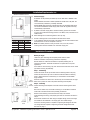
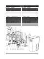
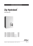
Installation and Operating Instructions
Zip Hydroboil
®
Instant boiling water
HS010
HS110
HS015
HS115
HS025 HS125
HS040 HS140
Hydroboil 10 Litre White
10552
Hydroboil 10 Litre Stainless Steel10551
Hydroboil 15 Litre White
11552
Hydroboil 15 Litre Stainless Steel
11551
Hydroboil 25 Litre White
12552
Hydroboil 25 Litre Stainless Steel
12551
Hydroboil 40 Litre White
04552
Hydroboil 40 Litre Stainless Steel
Zip Hydroboil - Installation & Operating Instructions - 81447 - April 2013 v1.03
Page 1 of 12
Description
Wall mounted Over-sink appliance for instant boiling water.
Features:
• Designed to operate within 1°C of boiling point.#
• Temperature controls automatically cut off the power in the event of temperature
control failure, boil dry cutout or a blocked vent pipe.
• Incorporating a pull down tap for precision filling of cups, it also locks ‘ON’ for filling
pots.
• Separates the cold water supply from the boiling chamber and the internal
condensing system retains steam within the heater.
• A stainless steel crevice free, boiling chamber with service access ports top and
bottom.
• High temperature thermal insulation with provision for service access to the boiling
chamber.
• Concealed plumbing and electrical connections.
• Choice of stainless steel or white enamelled steel case.
Installation Checklist
Before Installation:
A.
Read the instructions.
B.
Note: All fittings are supplied with the appliance kit except isolation valve and
pressure reduction valve, which are not supplied.
C.
Check the water quality to determine if extra filtration will be required. A potable mains water supply must be used.
To combat the build up of lime scale, a high performance inline filter (not supplied as standard equipment) may be ordered from your Zip service provider. (See Product Accessories page 4)
D. Check the appliance rating plate and ensure correct power is available for the
appliance.
E. Check the wall supporting the appliance is adequate for the total weight of the
appliance, when full of water.
Before Commissioning:
1.
Check the unit has been installed correctly.
2.
Check all plumbing fittings have been tightened.
3.
Ensure the vent pipe is positioned to drain correctly.
4.
Check all electrical connections are correct and there are no loose wires.
Commission:
7.
Flush the supply line before connecting.
8.
Turn on the water, allow to fill and check for leaks.
9.
Turn on the power.
Zip Hydroboil - Installation & Operating Instructions - 81447 - April 2013 v1.03
Page 2 of 12
Contents
Product Specifications / Accessories............................................................................................................................4
Read These Warnings First...................................................................................................................................... 4 - 5
Installation Requirements..............................................................................................................................................5
Installation Procedures............................................................................................................................................ 6 - 8
Step 1 – Positioning..................................................................................................................................6
Step 2 – Fastening....................................................................................................................................6
Step 3 – Connecting.................................................................................................................................7
a) Plumbing.................................................................................................................................7
b) Venting...................................................................................................................................7
c) Electrical.................................................................................................................................7
Step 4 – Assembling.................................................................................................................................8
Tap Fitting...................................................................................................................................8
Step 5 – Commissioning ..........................................................................................................................8
Operating Procedures ...................................................................................................................................................8
Wall Mounting Template Dimensions ...........................................................................................................................9
Earth Continuity Verification / Wiring Diagram..........................................................................................................10
Problem Solving...........................................................................................................................................................10
Maintenance.................................................................................................................................................................10
End of life disposal.......................................................................................................................................................10
Spare Parts...................................................................................................................................................................11
Warranty / Contact Details...........................................................................................................................................12
NOTE:
Read all instructions and precautions before proceeding. If in doubt, or need further guidance, please call Zip on 0845 6 005 005.
Please leave these instructions with the end user after installation.
This unit must be installed in accordance with water supply byelaws, current IEE regulations and relevant local authority
byelaws.
These products are approved to the LVD and EMC directives and CE endorsed.
Zip Hydroboil has been examined, tested and found when correctly fitted to comply with the requirements of the United
Kingdom Water Regulations / Byelaws (Scotland). The products are listed under the WRAS (Water Regulations Advisory
Scheme) Water Fittings and Materials Directory.
Zip Heaters (UK) Ltd cannot be held liable for any damages caused by failure to observe these instructions.
Page 3 of 12
Zip Hydroboil - Installation & Operating Instructions - 81447 - April 2013 v1.03
Product Specifications
Delivery
Recovery
Capacity
Cups @ any Cups per
Litres
one time
hour
Rating
kW @
230V
Width
mm
Depth
mm
Height
mm
Weight
Empty
Kg
Weight
Filled
Kg
3.0
390
244
600
15.0
29.5
Model
Finish
HS010
White
HS110
s/steel
10
60
180
3.0
390
244
600
15.0
29.5
HS015
White
15
90
180
3.0
390
299
600
16.0
34.5
HS115
s/steel
15
90
180
3.0
390
299
600
16.0
34.5
HS025
White
25
150
180
3.0
390
299
780
19.0
47.0
HS125
s/steel
25
150
180
3.0
390
299
780
19.0
47.0
HS040
White
40
240
360
2 x 3.0
515
284
840
25.0
71.0
HS140
s/steel
40
240
360
2 x 3.0
515
284
840
25.0
71.0
10
60
180
Water Inlet Pressure: 0.07 MPa (0.7 bar) minimum / 0.7 MPa (7 bar) maximum.
Protection class IP23
Accessories:
Inline Filter
FL104 10” (For taste and odour removal with scale reduction)
Drip Tray
ZD001 Stainless Steel (with drain)
ZD002 Stainless Steel (no drain)
Cup Dispenser
ZE001 Stainless Steel
ZE002 White Plastic
ZE010 Mug Rack
Tundish
ZD100 Wall Mounted Chrome Tundish
ZD101 Sink Mounted Chrome Tundish
Water Block
HE45004 Recommended; fitted into the supply line to minimise potential damage in the event of leakage.
Pressure Reducer
AQ3
Combined pressure reducer (set at 3.5 bar) and line strainer.
Read These Warnings First
IMPORTANT:
PLEASE READ THESE INSTRUCTIONS CAREFULLY.
NOTE THE SAFE OPERATIONAL REQUIREMENTS, WARNINGS AND CAUTIONS. USE THIS PRODUCT
CORRECTLY AND WITH CARE FOR THE PURPOSE FOR WHICH IT IS INTENDED. FAILURE TO DO
SO MAY CAUSE DAMAGE AND/OR PERSONAL INJURY, AND WILL INVALIDATE THE WARRANTY.
RETAIN THESE INSTRUCTIONS FOR FUTURE USE.
WARNING:
Situations that could cause injury to yourself or others.
CAUTION:
Situations that could cause damage to your appliance or other equipment.
NOTE:
Notes, usage tips or additional information.
Zip Hydroboil - Installation & Operating Instructions - 81447 - April 2013 v1.03
Page 4 of 12
Read These Warnings First Cont.
Safety
This appliance is not intended for use by persons (including children) with reduced physical sensory
or mental capabilities, or lack of experience and knowledge unless they have been given supervision
or instruction concerning use of the appliance by a person responsible for their safety.
Children should be supervised to ensure that they do not play with the appliance.
Please read all installation requirements, installation procedures and precautions before installing any
Zip Hydroboil instant boiling water heater.
Never attempt to install any Zip Hydroboil instant boiling water heater without reading all of the applicable instructions.
Care should be taken to avoid touching the metal body of the tap which can become very hot.
In some hard water areas where mineral scale accumulation in the boiling chamber of the Zip Hydroboil may become
a problem, consideration should be given to the maintenance required. A suitable form of water treatment may be
necessary.
As the installer, it is your responsibility to supply (if necessary) and install all valves as required by local regulations and
relevant standards.
The plumbing installation must be done in accordance with local Water Authority regulations and these Installation
Instructions.
This appliance must be earthed.
If the power cable is damaged it must be repaired only by a qualified technician. To avoid hazards, all installation
procedures must be carried out by a suitably qualified tradesperson. The power cable and power outlet must be in a safe
visible position for connection.
The power cable must be adequately secured.
Do not remove the cover of the heater under any circumstances without first isolating the heater from the power supply.
The appliance, its wiring and piping must not be modified in any way.
The appliance must be completely filled with water before being switched on.
In case of malfunction isolate the power supply immediately. In case of leaks also isolate the water supply. Repairs must
only be carried out by Zip Heaters (UK) Ltd or an authorised Zip service engineer.
Lifting
Take care when lifting the Zip Hydroboil unit. Some units may exceed safe lifting limits. If you feel this is beyond your
personal capabilities, please seek assistance with the lift. See specifications on page 4 for weights.
Operating Conditions:
The ambient temperatures this unit should operate within is 5ºC - 50ºC.
Frost protection: If this heater is located where ambient air temperature could fall below 5ºC; when the heater is not in
use, do not turn off the appliance electrically. This safeguard will protect the unit from frost damage but does not offer
the same protection to the connecting pipework and fittings.
This heater is intended only for indoor use and should never be installed outdoors or be exposed to the elements of nature.
This unit must not be positioned in an area that may be cleaned by a water jet. This unit must not be cleaned by a water jet.
Cleaning:
Hydroboil should only be wiped clean with a damp cloth. Never use abrasive cleaning agents or solvents on any
part of the Hydroboil, particularly the tap.
Installation Requirements
Before installing, ensure that the following are available:
a. Sufficient space to position the heater so there is at least 150mm clearance above the heater for service access,
65mm to its left and 20mm to its right – the tap outlet usually should be positioned at least 200mm above a
draining board or drip tray.
Page 5 of 12
Zip Hydroboil - Installation & Operating Instructions - 81447 - April 2013 v1.03
Installation Requirements Cont.
Minimum Clearance in mm
Size
10 Ltr
15 Ltr
25 Ltr
40 Ltr
Kw
3.0 kW
3.0 kW
3.0 kW
6.0 kW
Amps
13 A
13 A
13 A
30 A
b. Electrical supply.
A standard 13 amp double pole fused spur on the wall within 1500mm of the
heater.
Isolation switches must have a contact separation of at least 3mm in all poles. The
circuit should be protected by a suitably rated RCD.
HS140/HS040 (40ltr) should be provided with their own dedicated 30A supply.
The electrical installation should comply with current IEE regulations and any
Local Authority requirements.
c. A potable cold water supply with a minimum working pressure of 0.07 MPa
(0.7 bar) and a maximum working pressure of 0.7 MPa (7 bar) connected via an
isolation valve.
d. Outlet drainage to a sink draining board or to a drip tray.
e. Access to drainage from a vent situated at the base of the heater.
f. In all installation instances the walls of the heater must be vertical and the base
horizontal, there can be no exceptions to this rule.
g. Note: If the water pressure is likely to exceed 7 bar, a 3.5 bar pressure
reducing valve must be installed in the cold water supply line.
Installation Procedures
COLD
INLET
VENT
OUTLET
INLET
POSITION
Front View
Exposed
Services
Concealed
Services
VENT
POSITION
Before you begin
Locate the paper mounting-hole template packed with the heater.
Read the installation and operating instructions completely.
Decide whether to install with concealed or exposed plumbing and / or
electrical connections. Concealed connections are preferred for a superior
appearance.
If the heater is used for filling cups, then insert the flow restrictor into the outlet
pipe before securing tap assembly.
Step 1 - Positioning
Position the heater so the tap will drain onto the draining board or drip tray.
Position the base of the tap to be not less than 200 mm above the draining
board. ( Height should be increased only if it is essential to accommodate
larger vessels.)
Minimum clearances for service are 150 mm top, 65 mm left and 20 mm right.
Mark corner position on wall so to position mounting-hole template.
Step 2 - Fastening
Position mounting-hole template on the wall and drill mounting holes where
shown.
Drill holes for water inlet, vent outlet and wiring if it is intended to install the
heater with concealed electrical and plumbing connections.
Remove cover fastening screws and lift cover away from chassis.
Install plumbing and wiring, and prepare pipe ends for connection as shown in
step 3.
Screw heater chassis to the wall using the supplied fixings, ensure the fixings
are suitable for the substrate. If not supply your own suitable fixings.
Ensure the mounting surface is capable of supporting the weight of the filled
unit, fixings must be capable of supporting the heater weight when filled.
See chart on page 7.
Zip Hydroboil - Installation & Operating Instructions - 81447 - April 2013 v1.03
Page 6 of 12
Installation Procedures Continued
Approximate Weights When Filled
10 Litre models
29.5 kg
15 Litre models
34.5 kg
25 Litre models
47.0 kg
40 Litre models
71.0 kg
Step 3 – Connecting
Fig. a
250mm
a)Plumbing
Wiring
45mm
For exposed plumbing connection, connect the cold water inlet pipe from the base
of the heater directly to the 15mm or 1/2 inch BSP compression fittings.
For concealed plumbing connections, connect the cold water pipe through the rear
of the chassis using a 15mm or 1/2 inch BSP capillary elbow.
Concealed
Inlet
Concealed
Vent
Cold water pipes must be flushed before connection to the inlet. Any clogging due
to sediment or fines will adversely affect the operation of the heater.
It is recommended that the heater be installed with a isolating valve which allows
it to be isolated from the mains supply for servicing.
Water pressure requirements:
Fig. b
Minimum - 0.07 MPa (0.7 bar) Maximum - 0.7 MPa (7 bar).
Caution: If pressure is likely to exceed 0.7 MPa (7 bar), a pressure limiting valve must
be installed in the cold water supply line. Zip recommends a valve rated at 3.5 bar
(0.35 MPa) for this application (Zip part No. AQ3).
b) Venting
Vent line
Visible Tundish
Terminal Block
Concealed
cable entry
Page 7 of 12
Surface mount
cable entry
A vent at the base of the heater must be plumbed to a safe visible location as,
under certain conditions, it may discharge cold or boiling water and / or steam.
For exposed vent plumbing, connect vent outlet from the base of heater to a
15mm or half inch OD pipe which has a continuous fall, is no more than 3 metres
long, has no more than 3 right angle bends, and discharges to a waste water
drain.
For concealed vent plumbing (Fig. a), connect plumbing to the vent outlet from the
heater rear using a capillary elbow protruding 45mm from the wall. The plumbing
must then be directed to a tundish that must be in a visible location before being
plumbed away to waste.
Alternatively attach the tundish to the wall (Fig. b) and plumb away to waste.
c) Electrical
For concealed electrical connection, connect a power cable from the rear of the
heater to the terminal block within the heater as shown.
For surface mount installation run the power cable through the cable entry gland at
the bottom of the unit to the terminal block within the heater. Ensure the cable is
firmly secured.
Isolation switches must have a contact separation of at least 3mm in all poles.
Do not turn the power ON until water flows from the tap.
Zip Hydroboil - Installation & Operating Instructions - 81447 - April 2013 v1.03
Installation Procedures Continued
Flow Restrictor
Note: If the heater is used for filling cups,
then insert the flow restrictor into the outlet
pipe before securing tap assembly as above.
o-ring
Inlet water
temperature
15°C
10°C
10 Litre models
38 minutes
40 minutes
15 Litre models
40 minutes
43 minutes
25 Litre models
47 minutes
50 minutes
40 Litre models
60 minutes
64 minutes
Step 4 - Assembling
Place the heater case back onto the chassis and secure the two top and
four bottom fixing screws.
Caution! To ensure correct fitment of the tap assembly, follow the
instruction a to c below carefully.
Remove the black plastic cap from the hot outlet tube. PTFE tape has been
pre-applied to the hot outlet tube (check it is in good condition before
proceeding).
If not remove the damaged PTFE tape and carefully apply two to three
complete turns of new PTFE tape onto the threads in a clockwise direction
as shown alongside.
a. Screw the tap assembly clockwise on to the tap outlet tube.
b. Continue turning clockwise until the tap assembly just touches the
fascia without pressure.
c. Continue to turn the tap up to one full turn maximum until the tap
lever is in the upright position. (Do not force the tap upright; if you
cannot get the tap to the upright position without applying undue force,
remove the tap, start the thread in a new position or apply a few more
turns of PTFE and repeat the procedure.
Step 5 - Commissioning
Check previous steps. Turn water supply ON. Water is now flowing into
the heater, check all connections for leaks. Wait approximately 5 minutes
and check outlet tap for water. This is achieved by pulling the tap handle
forward.
Do Not turn on the power at this stage.
Ensure the tap handle is correctly adjusted to its optimum position.
• Screw the red knurled cap clockwise until hand tight without using
excessive force or a tool of any kind.
• Slowly unscrew the knurled cap anti-clockwise until the tap starts to
drip.
• Tighten the knurled cap a half a turn clockwise. The dripping will stop
and the tap will be set at the optimum position.
When the tap has been adjusted and the unit is full of water turn the power on.
After a short period, boiling water will be available and will be maintained
close to boiling point thereafter. Initial heating periods are shown in the table on
the left.
Operating Procedures
Tap Operation
Zip Hydroboil is fitted with a two-way tap for instant boiling water.
Care should be taken not to touch the metal body of the tap which can
become very hot.
For instant boiling water, gently pull the tap lever forward. Boiling water will
flow until the tap handle is released.
This operation gives fingertip flow control for safe filling of cups and mugs.
To fill larger vessels such as teapots and saucepans, rotate the lever 180
degrees and depress it until it locks into a horizontal position.
Boiling water will flow until the lever is returned to its normal vertical
position. This operation allows the vessel to be filled without holding your
hand where it may be affected by steam.
Zip Hydroboil - Installation & Operating Instructions - 81447 - April 2013 v1.03
Page 8 of 12
Template Dimensions
374mm (10L, 15L, 25L) 499mm (40L)
295mm (15L, 25L) 420mm (40L)
39.5mm
39.5mm
150
Ceiling Clearance
20mm
65mm
Wall Clearance
591mm 10L
591mm 15L
771mm 25L
831mm 40L
Cold inlet position
Concealed vent position
54mm
41mm
28mm
41mm
42mm
145mm
188mm (10L,15L, 25L)
313mm (40L)
41mm
200mm
Earthing Continuity Verification & Electrical Diagram
If required, an earth continuity test
can be performed by testing between
the earth pin on the products lead and
a exposed piece of metal on the case
and the tap body.
Page 9 of 12
Warning: This appliance must be earthed.
Following remedial service the earthing continuity of the heater must be checked by a
qualified technician using an appliance tester, or continuity tester of accuracy Class 5 or
better. Class 5 denotes an accuracy of 5% full scale deflection.
1. Isolate power supply.
2. Set meter to 0 ohm with leads connected together.
3. Connect one test lead to the earth pin on the three pin plug.
4. Connect the other test lead to a bare patch of metal (preferably on the edge) of the top of the
cover, then to the front cover of the unit, and then to the tap top under the plastic paddle.
This can be achieved by inserting the probe up from behind the paddle without losing water.
Warning: The water may be boiling - show extra care.
5. Test that in every instance the electrical resistance does not exceed 1ohm.
Zip Hydroboil - Installation & Operating Instructions - 81447 - April 2013 v1.03
Single Element Up To 3Kw with One Pole
T.O.L Thermal Over Load
Thermostat Controlled
HS140 & HS040 With Contactor
T.O.L: Thermal Over Load
Thermostat Controlled
Problem Solving
Symptom
Fails to dispense water.
Water not boiling.
Possible Cause
Solution
Water isolating valve turned off.
Check water supply valve.
Blocked filter, meter tube, strainer, jammed ball
valve assembly or airlock in transfer tube.
Contact a Zip authorised agent.
No power.
Check power supply.
Faulty thermostat, element, cutout or contactor.
Contact a Zip authorised agent.
Internal adjustment.
Contact a Zip authorised agent.
Runs out of boiling water and
fails to refill.
Outlet tap drips.
Overflow from vent.
Excessive steam from vent.
Power “on” but no heat.
Overload repeatedly tripping
with excessive steam.
Overload repeatedly tripping
without excessive steam.
Maintenance / Cleaning
For maintenance and six monthly safety checks, please refer to the Preventative Maintenance sheet No.85695 included
with the Hydroboil.
Maintenance should be carried out by a Zip authorised technician.
Cleaning Case: Do not use strong, corrosive, spray or abrasive cleaners.
Clean the case with a soft cloth or brush and mild soap and water.
Zip Hydroboil - Installation & Operating Instructions - 81447 - April 2013 v1.03
Page 10 of 12
Spare Parts
Key Part No
Description
Key Part No
1
Cistern lid clamp kit
15 SP90502 2 SP90120 Cistern lid gasket kit
17 SP90505 Tap nut kit
3
SP90490 Gasket kit
18 SP90506 Tap extension
4
SP90083 Float valve kit, with float
19 SP90486 Element kit 3.0kW 230V
5
SP90069 Jumper valve kit, with seals
20 SP90491 Cleaning hole cover kit
6
SP90102 Cistern float
21 SP90492 Drain cap & seal kit
SP90522 Cistern jet nozzle kit
SP90130 Lid clips
SP81230 Tap flow restrictor
SP6245 Description
Tap assembly complete
7
SP90494
Transfer tube kit - 2.4kW
7
SP90531 Transfer tube kit – 3kW
8
SP90495 Banjo screw
9
SP90496 O-ring kit complete
SP88318
Cistern tank
10 SP90517 Fascia & lens kit
SP88490 Cistern tank grommet kit
11 SP90110 Fascia light kit
SP6590
Contactor 40 litres
12 SP3947A Thermostat kit 1.5 - 25 litres
SP88343
Main tank 10L
12 SP3947A
Thermostat kit 40 litre
SP88344
Main tank 15L
13 SP1614T Overload kit
SP88345
Main tank 25L
14 SP90501 Tap top kit
SP88346
Main tank 40L
Page 11 of 12
Zip Hydroboil - Installation & Operating Instructions - 81447 - April 2013 v1.03
End of life disposal
The use of this crossed out wheeled bin logo indicates that this product needs to be disposed of
separately to any other household waste.
Within each of the European Union member countries, provisions have been made for the collection
and recycling of unwanted electrical and electronic equipment.
In order to preserve our environment we ask that you dispose of this product correctly.
Please contact Zip Customer Service for advice on 0845 6 005 005.
Warranty Information
Certain warranties may be implied by law into your contract with Zip. The
warranty provided below is additional to these implied warranties and nothing
set out below shall limit your statutory rights or rights at law.
Zip Heaters (UK) Ltd warrants that, should any part fail within 24 calendar
months of installation, that part will be repaired or replaced free of charge by
Zip or its Distributor or Service Provider, except as set out below, provided
the appliance is installed and used strictly in accordance with the instructions
supplied, and that failure is not due to accident, misuse, abuse, unsuitable
water conditions, or to any alteration, modification or repair by any party not expressly nominated by Zip.
No costs are payable by the customer other than any mileage or travelling-time
charges incurred by a Zip Service Provider or the cost of removal, cartage and
re-installation of any component of the appliance if it needs to be returned for
repair to Zip or its Distributor.
This warranty does not cover damage resulting from non-operation of the
appliance, the use of non authorised parts or consequential damage to any
other goods, furnishings or property.
No warranty applies to the life of any filtration cartridge installed with the
appliance as cartridge life may vary according to water quality and the rate of
water consumption. Zip does not exclude, restrict or modify any liability that cannot be excluded,
restricted or modified or which cannot, except to a limited extent, be excluded,
restricted or modified as between the owner or user and Zip under the laws
applicable.
Furthermore, this warranty does not displace any statutory warranty, but, to the
extent to which Zip is entitled to do so, the liability of Zip under any statutory
warranty will be limited at Zip’s option to the replacement of the appliance
or supply of equivalent appliance, the payment of the cost of replacing the
appliance or acquiring an equivalent appliance, or the payment of the cost of
having the appliance repaired or the repair of the appliance.
Registering Your Purchase
Head Office
Zip Heaters (UK) Ltd
14 Bertie Ward Way
Dereham
Norfolk NR19 1TE
Registering your Zip installation on the Zip website may help to establish date
of installation should it become necessary to service the appliance under terms
of the Zip warranty. To register your installation go to www.zipheaters.co.uk
and look under the heading “Warranty”.
Website: www.zipheaters.co.uk
[email protected]
Telephone: 0845 6 005 005
Facsimile: 01362 692 448.
Page 12
Zip Hydroboil - Installation & Operating Instructions - 81447 - April 2013 v1.03