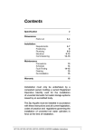
1
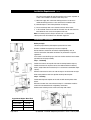
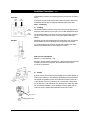
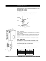
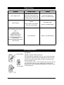
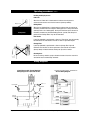
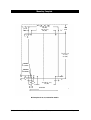
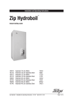
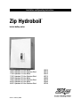
Installation and Operating Instructions
Zip Hydroboil
®
Instant boiling water
10552
10551
11552
11551
12552
12551
04552
04551
Hydroboil 10 Litre White
Hydroboil 10 Litre Stainless Steel
Hydroboil 15 Litre White
Hydroboil 15 Litre Stainless Steel
Hydroboil 25 Litre White
Hydroboil 25 Litre Stainless Steel
Hydroboil 40 Litre White
Hydroboil 40 Litre Stainless Steel
81447 - February 2004
HS010
HS110
HS015
HS115
HS025
HS125
HS040
HS140
Contents
Read These Warnings First . . . . . . . . . . . . . .3
Installation Requirements . . . . . . . . . . . . . . .3
Installation Procedures . . . . . . . . . . . . . . . . .4
Step 1 – Positioning . . . . . . .4
Step 2 – Fastening . . . . . . . .4
Step 3 – Connecting . . . . . . .5
a) Plumbing . . . . . . . .5
b) Venting . . . . . . . . .5
c) Electrical . . . . . . . .6
Step 4 – Assembling . . . . . . .6
Step 5 – Commissioning . . . .6
Problem Solving . . . . . . . . . . . . . . . . . . . . . .7
Operating Procedures . . . . . . . . . . . . . . . . . .7
Wiring Diagram . . . . . . . . . . . . . . . . . . . . . . .8
Mounting Template . . . . . . . . . . . . . . . . . . . .9
Connecting John Guest Fitting . . . . . . . . . . .10
Spare Parts . . . . . . . . . . . . . . . . . . . . . . . . . .10
Warranty . . . . . . . . . . . . . . . . . . . . . . . . . . . .12
Page 2 of 12
Zip Hydroboil - Installation & Operating Instructions - 81447 - February 2004
Read These Warnings First
Please read all installation requirements, installation procedures and precautions
before installing any Hydroboil instant boiling water heater.
Never attempt to install any Hydroboil instant boiling water heater without reading
all of the applicable instructions.
In some hard water areas where mineral scale accumulation in the boiling
chamber of the Hydroboil may become a problem, consideration should be given
to the maintenance required. A suitable form of water treatment may be
necessary.
The cold water supply to this appliance must be portable and fall within your local
water authority guidelines.
All plumbing connections must be made in accordance with local authority
requirements.
The Hydroboil instant boiling water heater is not intended for use by young
children or infirm people without supervision.
Young children should be prevented from having access to ensure that they are
not able to use or play with the heater.
If the installation site is located more than 1000 metres above sea level, the
installer should contact a authorized agent to obtain alternate PCB settings.
If the power supply cable is damaged it must be replaced by a Authorized Service
Provider or a qualified electrician.
Do not remove the cover of the heater under any circumstances without first
isolating the heater from the power supply.
Do not use strong, corrosive or abrasive cleaners to clean the case of the heater.
Frost protection: If this heater is located where ambient air temperature could fall
below 5ºC when the heater is not in use, do not turn off the appliance electrically.
This safeguard does not offer the same protection to the connecting pipework and
fittings.
The ambient temperatures this unit should operate with is 5ºC - 50ºC.
This heater is intended only for indoor use and should never be installed outdoors
or be exposed to the elements of nature.
This unit must not be positioned in an area that may be cleaned by a water jet.
This unit must not be cleaned by a water jet.
Installation Requirements
Before installing, ensure that the following are available:
Size
Kw
Amps
a) Sufficient space to position the heater so there is at least 150 mm
clearance above the heater for service access, 65 mm to its left and
20 mm to its right – the tap outlet usually should be positioned at least
200 mm above a draining board or drip tray.
10 Ltr
15 Ltr
25 Ltr
40 Ltr
2.4 kW
2.4 kW
3.6 kW
6.0 kW
10 A
10 A
15 A
25 A
b) Power supply is a fused spur for connection to the heater via a double pole
fused spur with a minimum break rating that adequately covers the maximum
power usage. Refer to table on the left.For units with 3.6 Kw element (25 ltr) or
multi element units (40 ltr) an isolating switch in the fixed wiring and attached
to a secure surface is required.
Zip Hydroboil - Installation & Operating Instructions - 81447 - February 2004
Page 3 of 12
Installation Requirements continued
This switch must provide all-pole disconnection and a contact seperation of
at least 3 mm installed in accordance with wiring rules.
c) Cold water supply with a minimum working pressure of 10 bar and a
maximum working pressure of 7 bar connected via an isolation valve.
d) Outlet drainage to a sink draining board or to a drip tray.
e) Access to drainage from a vent situated at the base of the heater.
f) In all installation instances the walls of the heater must be vertical and the
base horizontal, there can be no exceptions to this rule.
Note: If the water pressure is likely to exceed 7 bar, a 3.5 bar pressure
reducing valve must be installed in the cold water supply line.
Installation Procedures
Before you begin
Locate the paper mounting-hole template packed with the heater.
Read the installation and operating instructions completely.
Decide whether to install with concealed or exposed plumbing and / or
electrical connections. Concealed connections are preferred for a superior
appearance.
If the heater is used for filling cups, then insert the flow restrictor into the outlet
pipe before securing tap assembly.
Step 1 - Positioning
Position the heater so the tap will drain onto the draining board or drip tray.
Position the base of the tap to be not less than 200 mm above the draining
board. ( height should be increased only if it is essential to accommodate larger
vessels.)
Minimum clearances for service are 150 mm top, 65 mm left and 20 mm right.
Mark corner position on wall so to position mounting-hole template.
Step 2 - Fastening
Position mounting-hole template on the wall and drill mounting holes where
shown.
Drill holes for water inlet, vent outlet and wiring if it is intended to install the
heater with concealed electrical and plumbing connections.
Remove cover fastening screws and lift cover away from chassis.
Approximate Weights When Filled
10 litre models
29.5 kgs
15 litre models
34.5 kgs
25 litre models
47 kgs
40 litre models
71 kgs
Page 4 of 12
Zip Hydroboil - Installation & Operating Instructions - 81447 - February 2004
Installation Procedures Continued
Install plumbing and wiring, and prepare pipe ends for connection as shown in
step 3.
Front View
COLD
INLET
VENT
OUTLET
Screw heater chassis to wall using screws or bolts suited to the wall surface.
Screws/bolts must be able to support the following weights when filled.
Step 3 – Connecting
a)
Plumbing
INLET
POSITION
For exposed plumbing connection, connect the cold water inlet pipe from the
base of the heater directly to the 15 mm or 1/2 inch BSP compression fittings.
VENT
POSITION
For concealed plumbing connections, connect the cold water pipe through the
rear of the chassis using a 15 mm or 1/2 inch BSP capillary elbow (# 63
Elbows).
Cold water pipes must be flushed before connection to the inlet. Any clogging
due to sediment or fines will adversely affect the operation of the heater.
Side View
It is recommended that the heater be installed with a isolating valve which
allows it to be isolated from the mains supply for servicing.
45mm
Water pressure requirements:
Minimum - 0.1 bar, Maximum - 7 bar.
Elbow
Warning: If pressure is likely to exceed 7 bar, a pressure limiting valve must be
installed in the cold water supply line. We recommend a valve rated at
3.5 bar for this application.
250mm
Wiring
45 mm
b)
Venting
A vent at the base of the heater must be plumbed to a safe visible location as,
under certain conditions, it may discharge cold or boiling water and/or steam.
Concealed
Inlet
Concealed
Vent
For exposed vent plumbing, connect vent outlet from the base of heater to a
15 mm OD pipe which has a continuous fall, is no more than 3 metres long,
has no more than 3 right angle bends, and discharges to a waste water drain.
For concealed vent plumbing, connect plumbing to the vent outlet from the
heater rear using a capillary elbow protruding 45 mm from the wall.
Exposed vent
With Tundish
Zip Hydroboil - Installation & Operating Instructions - 81447 - February 2004
Page 5 of 12
Installation Procedures continued
Alternatively attach a tun dish to the wall as shown and plumb away to waste.
Wall mounted tundish - p/n 99017
Sink mounted tundish- p/n 99018
c)
Electrical
For concealed electrical connection, connect a power cable from the
rear of the heater to the terminal block within the heater as shown.
Do not turn the power ON until the heater is filled with water.
Thermostat
Terminal Block
Contactor
Vent
Cold inlet
n
tinued
continued
Step 4 - Assembling
Place the heater case back onto the chassis and secure the two top and four
bottom fixing screws.
Screw the tap assembly clockwise onto the tap outlet tube using PTFE tape.
Screw the tap clockwise until the tap assembly touches the fascia without
pressure.
Continue to turn the tap a further one full turn until the tap lever is upright.
Step 5 - Commissioning
Check previous steps. Turn water supply ON, check connections for leaks.
Turn tap handle to the “lock down” side and leave open until water starts
flowing from the outlet. Return the handle to the closed position to stop water
flow and turn the handle 180º to the “cup fill” position.
See page 8 for LED Display information.
Turn power on. After a short time, boiling water will be available and will be
maintained close to boiling point thereafter. Initial heating periods are:
Page 6 of 12
Inlet water temperature
15°C
10°C
10 Litre models
38 minutes
40 minutes
15 Litre models
40 minutes
43 minutes
25 Litre models
47 minutes
50 minutes
40 Litre models
60 minutes
64 minutes
Zip Hydroboil - Installation & Operating Instructions - 81447 - February 2004
Problem Solving
Symptom
Possible Cause
Solution
Fails to dispense water.
Water isolating valve turned off.
Blocked filter, blocked meter tube,
blocked strainer, jammed ball valve
assembly, airlock in transfer tube.
Check water supply valve.
Contact a Zip authorised agent.
No power.
Water not boiling.
Runs out of boiling water and fails to
refill.
Outlet tap drips.
Overflow from vent.
Excessive steam from vent.
Power “on” but no heat.
Overload repeatedly tripping with
excessive steam.
Overload repeatedly tripping without
excessive steam.
Check power supply.
Faulty thermostat, faulty element,
faulty cutout, faulty contactor.
Contact a Zip authorised agent.
Internal adjustment.
Contact a Zip authorised agent.
Operating procedures
Tap Operation
“Cup fill” position
Hydroboil is fitted with a two-way safety tap.
The tap assembly has two positions, one is the “cup fill” quick return mode.
This operation is achieved by having the handle with the curved cam at the
base of the tap handle facing you. When the handle is released this mode
allows instant water cutoff.
“Pot fill” position
The second mode is “pot fill”, to use this position rotate the handle 180º from
the “cup fill” side so a flat face cam is showing at the handle base. This
operation allows a vessel to be filled without holding your hand where it may
be affected by steam.
Zip Hydroboil - Installation & Operating Instructions - 81447 - February 2004
Page 7 of 12
Operating proceedures continued
Reading the Display Screen
Power On
When the text 'Power On' is illuminated this indicates that the power is
connected and turned on and that the heater is operating normally.
Display Screen
Boiling Water
When the text 'Boiling Water' is illuminated this indicates that the contents of
the boiling chamber has been brought to boiling point and is being maintained
(normally within 1°C of boiling point). During the initial heat-up the contents of
the boiling chamber may be below boiling point for a period, and during that
period the text 'Boiling Water' may not be illuminated.
Boiling Water
Filter Active
If your Zip Hydroboil is specified with a filter the ‘ Filter Active’ text will normally
be illuminated. This indicated that the filter is within its specified lifespan.
Change Filter
If your Zip Hydroboil is specified with a filter the ‘Change Filter’ light will
illuminate when the filter is due to replacement. The local toll free number
(directly above) will also illuminate showing the Zip service number.
Cleaning Case
Do not use strong, corrosive, spray or abrasive cleaners. Clean the case with a
soft cloth or brush and mild soap and water.
Wiring Diagrams
Single Element with Thermal Overload
Wiring Diagram for 10,15 and 25 Litre.
N
40 Litre Wiring Diagram
L
reset t.o.l.
fascia lights
thermostat
tº
t.o.l.
element
assembly
element
Page 8 of 12
Zip Hydroboil - Installation & Operating Instructions - 81447 - February 2004
Mounting Template
374 (10L, 15L, 25L)
499 (40L)
295 (15L, 25L)
420 (40L)
120
CLEAR
39.5
150
CLEAR
39.5
20
TYP
591 (10L, 15L)
771 (25L)
831 (40L)
EXTERNAL
PLUMBING
INTERNAL
PLUMBING
54
41 TYP
28
41
41
COLD
INLET
VENT
42
145
188 (10L,15L, 25L)
313 (40L)
BENCH TOP
Wall template for 10, 15, 25 & 40 litre models.
Zip Hydroboil - Installation & Operating Instructions - 81447 - February 2004
Page 9 of 12
Connecting John Guest Fittings
Spare Parts
Page 10 of 12
Key
Part
Description
1
90096
Cistern Lid Clamp Kit
2
90097
Overload Kit
3
90120
Disc, Capsule, Lid, Gasket Kit
4
90490
Gasket Kit
5
90121
Cistern Lid Gasket Kit
6
90083
Float Valve Kit
7
90069
Jumper Valve kit
8
90496
O-ring Kit
9
90102
Cistern Float S/Nut Kit
10
90495
Banjo Screw Kit
11
90110
Fascia Light Kit
12
90501
Tap Top Kit
13
90499
Fascia Lens Kit
14
90494
Metering Tube Kit 2400 w
90527
Metering Tube Kit 3600 w
90526
Metering Tube Kit 6000 w
15
90502
Tap Assembly Complete
16
90081
Thermostat Kit 2-25 ltr
90080
Thermostat Kit 40 ltr
17
90491
Clean Hole Cover Kit
18
90123
Element Kit 2400 w / 240 v
90124
Element Kit 3600 w / 240 v
90125
Element Kit 3000 w / 240 v
19
90107
Filter Cold Inlet kit
20
90492
Drain Cap and Seal Kit
21
90174
Contactor Kit 240 v CL01A310TR
Zip Hydroboil - Installation & Operating Instructions - 81447 - February 2004
17
4
16
4
3
2
19
1
9
4
5
18
6
8
14
10
7
8
20
4
17
8
11
21
13
15
12
Spare Parts
Zip Hydroboil - Installation & Operating Instructions - 81447 - February 2004
Page 11 of 12
#
Warranty Information
The Zip appliance you have chosen is precision-built from the finest materials
available and should give many years of trouble free service.
Certain warranties may be implied by law into your contract with Zip. The
warranty provided below is additional to these implied warranties and nothing
set out below shall limit your statutory rights or rights at law.
Zip Heaters (UK) Pty Ltd warrants that, should any part fail within 24 calendar
months of installation, that part will be repaired or replaced free of charge by
Zip or its Distributor or Service Provider, except as set out below, provided the
appliance is installed and used strictly in accordance with the instructions
supplied, and that failure is not due to accident, misuse, abuse, unsuitable
water conditions, or to any alteration, modification or repair by any party not
expressly nominated by Zip.
No costs are payable by the customer other than any mileage or travelling-time
charges incurred by a Zip Service Provider or the cost of removal, cartage and
re-installation of any component of the appliance if it needs to be returned for
repair to Zip or its Distributor.
This warranty does not cover damage resulting from non-operation of the
appliance or consequential damage to any other goods, furnishings or property.
No warranty applies to the life of any filtration cartridge installed with the
appliance as cartridge life may vary according to water quality and the rate of
water consumption.
Zip does not exclude, restrict or modify any liability that cannot be excluded,
restricted or modified or which cannot, except to a limited extent, be excluded,
restricted or modified as between the owner or user and Zip under the laws
applicable.
Furthermore, this warranty does not displace any statutory warranty, but, to the
extent to which Zip is entitled to do so, the liability of Zip under any statutory
warranty will be limited at Zip's option to the replacement of the appliance or
supply of equivalent appliance, the payment of the cost of replacing the
appliance or acquiring an equivalent appliance, or the payment of the cost of
having the appliance repaired or the repair of the appliance.
Registering Your Purchase
Head Office
Registering your Zip installation on the Zip website may help to establish date
of installation should it become necessary to service the appliance under terms
of the Zip warranty. To register your installation go to www.zipheaters.co.uk and
look under the heading "Warranty".
Zip Heaters (UK) Pty. Ltd.
14/15 Bertie Ward Way
Rashe’s Green Dereham
NORFOLK NR19 1TE
Website: www.zipheaters.co.uk
Telephone: 0870 608 8888
Facsimile: 01362 692 448
Page 12 of 12
Zip Hydroboil - Installation & Operating Instructions - 81447 - February 2004