1
Operator’s Manual
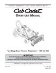
42-inch Snow Thrower Attachment
For 600-series Lawn Tractors
Model
OEM-190-627
NOTE: This snow thrower attachment will NOT fit on all 600-series lawn tractors. It is NOT designed for
and will NOT operate safely or properly on FastAttach™ compatible tractors. Check your tractor’s right fender for the
FastAttach™ label before attempting to mount this attachment.
NOTE: This snow thrower attachment will NOT fit on ANY 800-series garden tractors, regardless of the tractor’s
FastAttach™ compatibility.
MTD PRODUCTS INC. P.O. BOX 368022 CLEVELAND, OHIO 44136-9722
PRINTED IN U.S.A.
FORM NO. 770-10056A
(05/00)
FINDING MODEL NUMBER
This Operator’s Manual is an important part of your new snow thrower attachment. It will help you assemble,
prepare and maintain the unit for best performance. Please read and understand what it says.
Before you start assembling your new equipment, please locate the model plate on the
equipment and copy the information from it in the space provided below. The information on the
model plate is very important if you need help from our Customer Support Department or an
authorized dealer.
You can locate the model number by looking on the rear, right portion of the snow thrower impeller housing. A
sample model plate is explained below. For future reference, please copy the model number and the serial number
of the equipment in the space below.
Model Plate
Figure 1
•
An example of what the model plate will look like is shown below.
(Model Number)
(Serial Number)
Copy the model number here:
Copy the serial number here:
MTD PRODUCTS INC
CLEVELAND, OHIO 44136
CALLING CUSTOMER SUPPORT
If you have difficulty assembling this product or have any questions regarding the controls, operation or
maintenance of this unit, please call the Customer Support Department.
Call 1- (330) 220-4MTD (4683) or 1- (800)-800-7310 to reach a Customer Support representative.
Please have your unit’s model number and serial number ready when you call. See previous section
to locate this information. You will be asked to enter the serial number in order to process your call.
•
Although both numbers are important, you will be asked to enter only your serial number before your call can
be processed.
For more details about your unit, visit our website at www.mtdproducts.com
2
SECTION 1: IMPORTANT SAFE OPERATION PRACTICES
WARNING: This symbol points out important safety instructions which, if not followed, could endanger
the personal safety and/or property of yourself and others. Read and follow all instructions in this manual
before attempting to operate this machine. Failure to comply with these instructions may result in personal injury. When you see this symbol—heed its warning.
WARNING: Engine Exhaust, some of its constituents, and certain vehicle components contain or
emit chemicals known to State of California to cause cancer and birth defects or other reproductive harm.
DANGER: This machine was built to be operated according to the rules for safe operation in this manual. As with any type of power equipment, carelessness or error on the part of the operator can result in
serious injury. This machine is capable of amputating hands and feet and throwing objects. Failure to
observe the following safety instructions could result in serious injury or death.
TRAINING
1.
2.
3.
4.
5.
6.
7.
6.
Read, understand, and follow all instructions on the
machine and in the manual(s) before attempting to
assemble and operate. Keep this manual in a safe place
for future and regular reference and for ordering
replacement parts.
Be familiar with all controls and their proper operation.
Know how to stop the machine and disengage them
quickly.
Never allow children under 14 years old to operate this
machine. Children 14 years old and over should read and
understand the operation instructions and safety rules in
this manual and should be trained and supervised by a
parent.
Never allow adults to operate this machine without proper
instruction.
Thrown objects can cause serious personal injury. Plan
your snow throwing pattern to avoid discharge of material
toward roads, bystanders and the like.
Keep bystanders, helpers, pets and children at least 75
feet from the machine while it is in operation. Stop
machine if anyone enters the area.
Exercise caution while operating tractor with this
attachment, especially when traveling in reverse.
7.
8.
PREPARATION
1.
2.
3.
4.
5.
Thoroughly inspect the area where the equipment is to be
used. Remove all door mats, newspapers, sleds, boards,
wires and other foreign objects which could be thrown by
the auger/impeller.
Always wear safety glasses or eye shields during
operation and while performing an adjustment or repair to
protect your eyes. Thrown objects which ricochet can
cause serious injury to the eyes.
Do not operate without wearing adequate winter outer
garments. Do not wear jewelry, long scarves or other
loose clothing which could become entangled in moving
parts. Wear footwear which will improve footing on
slippery surfaces.
Adjust collector housing height to clear gravel or crushed
rock surfaces.
Disengage all clutches and shift into neutral before
starting the engine.
Never attempt to make any adjustments while engine is
running, except where specifically recommended in the
operator’s manual(s).
Let tractor engine and attachment adjust to outdoor
temperature before starting to clear snow.
To avoid personal injury or property damage use extreme
care in handling gasoline. Gasoline is extremely
flammable and the vapors are explosive. Serious
personal injury can occur when gasoline is spilled on
yourself or your clothes which can ignite. Wash your skin
and change clothes immediately.
a. Use only an approved gasoline container.
b. Extinguish all cigarettes, cigars, pipes and other
sources of ignition.
c. Never fuel machine indoors.
d. Never remove gas cap or add fuel while the
engine is hot or running.
e. Allow engine to cool at least two minutes before
refueling.
f. Never over fill fuel tank. Fill tank to no more than ½
inch below bottom of filler neck to provide space
for fuel expansion.
g. Replace gasoline cap and tighten securely.
h. If gasoline is spilled, wipe it off the engine and
equipment. Move machine to another area. Wait 5
minutes before starting the engine.
i. Never store the machine or fuel container inside
where there is an open flame, spark or pilot light
(e.g. furnace, water heater, space heater, clothes
dryer etc.).
j. Allow machine to cool at least 5 minutes before
storing.
OPERATION
1. Do not put hands or feet near rotating parts, in the auger/
2.
3.
4.
3
impeller housing or discharge chute. Contact with the
rotating parts can amputate hands and feet.
Never operate with a missing or damaged discharge
chute. Keep all safety devices in place and working.
Never run an engine indoors or in a poorly ventilated
area. Engine exhaust contains carbon monoxide, an
odorless and deadly gas.
Do not operate machine while under the influence of
alcohol or drugs.
7.
8.
9.
10.
11.
12.
13.
14.
15.
16.
17.
18.
MAINTENANCE AND STORAGE
1. Never tamper with safety devices. Check their proper
operation regularly.
2. Disengage power take-off, lower the attachment, set the
parking brake, stop engine and remove key to prevent
unintended starting. Wait until the auger/impeller comes
to a complete stop before cleaning, repairing, or
inspecting.
3. Check bolts, and screws for proper tightness at frequent
intervals to keep the machine in safe working condition.
Also, visually inspect machine for any damage.
4. Do not change the engine governor setting or over-speed
the engine. The governor controls the maximum safe
operating speed of the engine.
5. Snow thrower shave plates and skid shoes are subject to
wear and damage. For your safety protection, frequently
check all components and replace with original
equipment manufacturer’s (O.E.M.) parts only. “Use of
parts which do not meet the original equipment
specifications may lead to improper performance and
compromise safety!”
6. Check clutch controls periodically to verify they engage
and disengage properly and adjust, if necessary. Refer to
the PTO and safety interlock system in your tractor’s
operator’s manual for instructions.
7. Maintain or replace safety and instruction labels, as
necessary.
8. Observe proper disposal laws and regulations for gas, oil,
etc. to protect the environment.
9. Prior to storing, run machine a few minutes to clear snow
from machine and prevent freeze up of auger/impeller.
10. Never store the machine or fuel container inside where
there is an open flame, spark or pilot light such as a water
heater, furnace, clothes dryer etc.
11. Always refer to the Operator’s Manual for proper
instructions on off-season storage.
WARNING — YOUR RESPONSIBILITY:
Restrict the use of this power machine to persons who read, understand and follow the warnings and instructions in
this manual and on the machine.
DANGER
DANGER
1. KEEP AWAY FROM ROTATING IMPELLER
AND AUGER. CONTACT WITH IMPELLER
OR AUGER CAN AMPUTATE HANDS AND FEET.
2. DISENGAGE PTO, STOP ENGINE, SET PARK
BRAKE, AND REMAIN ONMACHINE UNTIL
ALL MOVING PARTS HAVE STOPPED BEFORE
UNCLOGGING OR SERVICING.
3. TO AVOID THROWN OBJECTS INJURIES,
NEVER DIRECT DISCHARGE AT BYSTANDERS.
USE EXTRA CAUTION WHEN OPERATING ON
GRAVEL SURFACES.
DANGER
6.
Muffler and engine become hot and can cause a burn. Do
not touch.
Exercise extreme caution when operating on or crossing
gravel surfaces. Stay alert for hidden hazards or traffic.
Do not carry passengers.
Exercise caution when changing direction and while
operating on slopes.
Plan your snow throwing pattern to avoid discharge
towards windows, walls, cars etc. To avoid property
damage or personal injury caused by a ricochet.
Never direct discharge at children, bystanders and pets
or allow anyone in front of the machine.
Do not overload machine capacity by attempting to clear
snow at too fast of a rate.
Never operate this machine without good visibility or light.
Disengage power to the auger/impeller when
transporting or not in use.
Never operate machine at high transport speeds on
slippery surfaces. Look down and behind and use care
when in reverse.
If the machine should start to vibrate abnormally, stop the
engine, disengage the power take-off, lower the
attachment and set the parking brake. Inspect thoroughly
for damage. Repair any damage before starting and
operating.
Disengage the power take-off, lower attachment, set the
parking brake and stop engine before you leave the
operating position. Wait until the auger/impeller comes to
a complete stop before unclogging the discharge chute,
making any adjustments, or inspections.
Never put your hand in the discharge or collector
openings. Always use a clearing tool to unclog the
discharge opening.
Use only attachments and accessories approved by the
manufacturer (e.g. wheel weights, tire chains, cabs etc.).
If situations occur which are not covered in this manual,
use care and good judgment. Contact your dealer or
telephone 1-800-800-7310 for assistance and the name
of your nearest servicing dealer.
AVOID INJURY FROM
ROTATING AUGER KEEP HANDS, FEET
AND CLOTHING AWAY.
5.
4. READ OPERATOR’S MANUAL.
5. FOR BALLAST INFORMATION REFER TO
YOUR ATTACHMENT MANUAL.
NEVER PUT HAND IN CHUTE. CONTACT WITH
ROTATING PARTS CAN AMPUTATE FINGERS
AND HANDS.
DO NOT UNCLOG DISCHARGE CHUTE WHILE
ENGINE IS RUNNING.
SHUT OFF ENGINE AND REMAIN BEHIND
HANDLES UNTIL ALL MOVING PARTS HAVE
STOPPED BEFORE UNCLOGGING.
Figure 2 Safety Labels Found on Snow Thrower
4
SECTION 2: TO THE OWNER
Model 627 42-inch two-stage snow thrower is designed for use on 600-series lawn tractors manufactured in
1996 or later ONLY. It will NOT fit nor operate properly or safely on ANY other tractor. It will NOT fit on any
FastAttach™ compatible tractor.
NOTE: If your 600-series lawn tractor was manufactured prior to 1996, model 627 snow thrower attachment can be
mounted on the tractor with special instructions and minor modifications to the tractor. Phone our Customer Support
Department as instructed on page 2 for details.
NOTE: References to LEFT and RIGHT indicate the left and right sides of the tractor when facing forward in the
operator’s position. Reference to the FRONT indicates the grille end; to the REAR the drawbar end.
SECTION 3: CONTENTS OF CARTON
Before beginning installation, remove all parts from the carton to make sure everything is present. Carton contents
are listed below and shown in Figure 3. Part numbers are shown in parentheses.
•
One Auger Housing Assembly
•
Two Spare Shear Bolts (710-0890A)
& Hex Lock Nuts (712-0429)
•
One Undercarriage Assembly with
Upper V-belt (754-0449) & Lower V-belt (754-0330)
•
One Flat Washer (736-3019)
•
One Hairpin Clip (714-0145)
•
One Support Carriage Assembly
•
One Chute Directional Control with Tilt Lever
•
Two Hex Screws (710-0376)
•
One Lift Handle Assembly with Cable
•
Two Belleville Washers (736-0242)
•
One Upper Chute Crank Rod
•
Two Lock Washers (736-0119)
•
Two Self-adhesive Reflectors (730-3000)
•
Two Hex Nuts (712-3010)
•
Two 1¼-inch Cotter Pins (714-0470)
•
Three Cable Ties (725-0157)
•
One ¾-inch Cotter Pin (714-0507)
•
One Extension Spring (732-0626)
Upper Chute Crank Rod
Undercarriage Assembly
with Upper V-belt & Lower V-belt
Chute Directional Control
with Tilt Lever
Support Carriage Assembly
Lift Handle Assembly
With Cable
Self-adhesive
Reflectors
Extension
Spring
Cable
Ties
Hex Screws,
Belleville Washers,
Lock Washers
and Hex Nuts
1¼ Cotter Pins
Figure 3
5
Auger Housing Assembly
Flat Washer
& Hairpin Clip
¾-inch
Cotter Pin
Spare Shear Bolts
& Hex Lock Nuts
SECTION 4: ASSEMBLY
WARNING: Before installing attachment,
place tractor on a firm and level surface. Place
the PTO in the disengaged (OFF) position, set
the parking brake, shut engine off and remove
key to prevent unintended starting.
NOTE: Your tractor’s cutting deck and PTO belt must
be removed prior to mounting the snow thrower
attachment. Refer to your tractor’s Operator’s Manual
for detailed instructions. Retain all the deck hardware
and store it in a safe place. If your tractor is equipped
with any front-end accessory such as a front bumper
kit, it must also be removed.
Hex Screw,
Belleville Washer
NOTE: It is strongly recommended that a second
person act as an assistant throughout the assembly of
the snow thrower attachment. Having a second person
present eases the completion of many of the steps.
NOTE: The lock washer and hex nut
are on the INSIDE of the pivot bracket.
Figure 4
Mounting the Support Carriage Assembly
1. Fasten the provided hex screws, belleville washers,
lock washers and lock nuts to the tractor’s front
pivot bracket as illustrated in Figure 4 on both the
left side and the right side. Do NOT tighten the
hardware at this point in the assembly.
2. Place the tractors front tires on 2x4s to bring the
tractor’s front end up a few inches and allow
clearance for positioning the support carriage.
3. Remove the hex screws, lock washers and hex
nuts from the both sides of the rear of the support
carriage assembly.
4. Place the support carriage assembly between the
tractor’s front tires so that the large notch on both
sides of the support carriage straddles the tractor’s
front pivot bar. See Figure 5.
5. Position the rear of the support carriage so that the
holes where the hardware was just removed align
with the holes in the tractor’s frame rail.
Front Pivot Bar
Large Notch
Support Carriage
Figure 5
NOTE: Make certain that the support carriage is to the
OUTSIDE of the frame rail on both sides of the tractor.
6. Reinsert the rearmost hex screw removed in Step 3
through the aligning holes in both the support
carriage assembly and the tractor’s frame rail.
Fasten with the lock washer and hex nut but do not
tighten the hardware at this time. See Figure 6.
7. Pivot the front of the support carriage upward until
the small grooves found in the front portion of
support carriage slide between the belleville
washers inserted in step 1 and the tractor’s front
pivot bracket. See Figure 7.
Hex Screw
NOTE: The lock washer and hex nut are
on the INSIDE of the tractor’s frame rail.
Figure 6
6
8. Reinsert the remaining hex screws removed in
Step 4 through the remaining aligning holes in both
the support carriage assembly and the tractor’s
frame rail (just behind the tractor’s front pivot
bracket). Securely fasten with the remaining lock
washers and hex nuts. See Figure 7.
9. Securely tighten all the other hardware used to
mount the support carriage assembly.
Mounting the Undercarriage Assembly
1. Remove the carriage bolts, lock washers and hex
nuts from both sides of the front of the undercarriage assembly.
2. Carefully position the undercarriage assembly
right-side up beneath the tractor and stretch both
belts out toward the front of the tractor to keep them
from getting in the way of completing the following
steps.
Hex
Screw
Support Carriage Groove
Figure 7
NOTE: The zinc-plated double pulley is located in the
REAR of the undercarriage assembly.
3. Position the slot found on both the left, rear and the
right, rear sides of the undercarriage onto the
tractor’s running board rod. See Figure 8.
4. Pivot the undercarriage upward allowing the
tractor’s front lift links to suspend between the
undercarriage’s left side plates and the tractor’s
frame rails. The tractor’s adjustable lift link (an ‘L’shaped rod found on the front, right) will suspend
through the opening in the right side of the
undercarriage.
NOTE: The rear lift links (See Figure 8) are unaffected
by this assembly and not used in any regard by the
snow thrower attachment. Both can be ignored.
Rear Lift Links
Running Board Rod
Front Lift Link
5. With the undercarriage’s side plates positioned to
the inside of the support carriage mounted earlier,
reinsert the carriage bolts removed in step 1
through aligning holes in both the undercarriage
assembly and support carriage assembly. See
Figure 9.
6. Secure the undercarriage to the support carriage
by refastening the lock washers and hex nuts
removed in Step 1 to the carriage bolts just
inserted.
NOTE: The tractor’s frame and running
board are ‘cut away’ for clarity in this figure.
Figure 8
NOTE: Disregard both the upper drive belt and the
lower drive belt at this point in the assembly of the snow
thrower. They will both be routed in later steps.
Attaching the Reflectors
Side Plate
1. Peel off the backing from each of the reflectors to
expose the adhesive surface.
2. Adhere the reflectors to the rear of the tractor’s
fender (one on the left and one on the right) so that
the reflectors simulate taillights.
Carriage Bolts
NOTE: The lock washer and hex nut are on
the INSIDE of the support carriage assembly.
Figure 9
7
Attaching The Lift Handle
1. Remove the hex screws and flange nuts from the
lower portion of the lift handle.
2. Attach the lift handle to the lift bracket found on the
right side of the support carriage assembly with the
two hex screws and two flange lock nuts just
removed. See Figure 10.
Vertical
Links
Mounting the Auger Housing Assembly
1. Carefully remove the 2x4s placed under the
tractor’s front tires in Step 2 of Mounting the Support
Carriage Assembly.
2. Position the auger housing assembly closely in
front of the tractor’s front-end.
Hex Screws
IMPORTANT: Having a second person assist you will
Lift Handle
significantly ease the following steps.
3. Place the 2x4s removed in Step 1 beneath the
auger housing assembly’s lower lift links, just
behind the skid plate. This will cause the housing to
tilt slightly forward and ease in completing the
following steps.
4. Remove the clevis pin, flat washer and hairpin clip
from the lower portion of each vertical link on the
front of the support carriage assembly. See Figure
10.
5. Align the hole in the lower portion of each vertical
link with the hole found near the center of each of
the auger assembly’s lower lift links and reinsert
the clevis pins just removed through these aligned
holes.
6. Secure the vertical lift links to the lower lift links by
fastening with the flat washers and hairpin clips
also removed in Step 4. See Figure 11.
7. Remove the hex screws, flat washers and crown
nuts from the rear portion of each lower lift link.
8. Grasp the auger housing support bar, refer to
Figure 11, on the left rear (have a second person
grasp the support bar on the right rear) portion of
the auger housing and lift upward until the holes
found on the rear of the lower lift links are aligned
with the holes found on both (left & right) sides of
the support carriage.
9. Reinsert the hex screws (with one flat washer each)
removed in Step 7 through the aligning holes.
10. Secure the lower lift links to the support carriage by
fastening with the crown nuts and remaining two flat
washers removed in Step 8 in addition to the two
1¼-inch cotter pins provided.
Figure 10
Vertical Link Secured
to Lower Lift Link
Figure 11
IMPORTANT: After inserting, bend the tips of the cotter
pins outward to prevent them from backing out of the
hex screws.
Lower Lift Link Secured
to Support Carriage
Figure 12
8
Auger Housing
Support Bar
11. Remove the hex screws and hex nuts from the rear
portion of each upper lift link.
12. Have an assistant grasp the upper portion of the
auger housing and pivot the assembly upward until
the holes of the upper links align with holes in the
front of the support carriage.
13. Reinsert the hex screws removed in Step 11
through the aligning holes and secure the upper lift
links to the support carriage by fastening with the
hex nuts also removed in Step 12. See Figure 13.
IMPORTANT: Make certain that the hex nut securing the
left upper lift link is positioned to the INSIDE of link. This
will avoid any interference when attaching the chute
directional control in following steps.
Upper Lift Link Secured
to Support Carriage
Attaching the Chute Directional Control
1. Remove the hex screws and flange nuts from the
lower portion of the chute directional control.
2. Attach the chute directional control to the upper lift
link on the left side of the auger housing assembly
with two hex screws and two flange nuts just
removed. See Figure 14.
3. Slide the upper chute crank rod through the eyelet
in the top of the chute directional control and the
eyebolt found midway down.
4. Pivot the lower chute crank rod upward and secure
it to the upper chute crank rod with the ¾-inch cotter
pin provided. See Figure 14.
5. Fasten the chute tilt cables to the chute directional
control with the three cable ties provided. Pull the
cable ties until they’re snug and trim off any excess.
Figure 13
Upper
Rod
Lower
Rod
Routing the Upper Drive Belt
Hex Screws
1. Make sure that the “V” side of the upper drive belt is
seated firmly in the upper portion of the double
pulley found in the rear of the undercarriage
assembly.
2. Route the opposite end of the upper drive belt
around the engine pulley, to the INSIDE of the belt
keeper pins found on either side of the engine
pulley.
3. Place the tractor’s lift lever in the lowest reachable
engagement notch.
4. Hook one end of the extension spring provided into
the hole on the left side of the undercarriage idler
bracket’s surface, just to the rear of the belt keeper.
See Figure 15
5. Using a pair of vise grips, hook the other end of the
extension spring to a hole in the tractor’s left frame
rail. See Figure 15.
Chute Directional Control
Figure 14
Hook Extension Spring Here
WARNING: Always wear safety glasses or
eye shields during operation and while
performing an adjustment or repair to protect
your eyes.
Double Pulley
Belt Keeper on Idler Bracket
Figure 15
9
Routing the Lower Drive Belt
1. Loosen, but do NOT remove the flange nut which
secures the belt keeper to the drive mounting
bracket. See Figure 16.
2. Make sure that the “V” side of the lower drive belt is
seated firmly in the lower portion of the double
pulley found in the rear of the undercarriage
assembly.
3. Route the opposite end of the lower drive belt
around the snow thrower’s drive pulley, to the
INSIDE of the belt keeper loosened in Step 1.
Flange Nut
Drive Mounting
Bracket
NOTE: Having a second person carefully pivot the
double-idler pulley mounted beneath the undercarriage
toward the left side of the tractor will relieve tension on
the lower drive belt and ease in routing it around the
drive pulley.
NOTE: View shown is from above the tractor.
4. Retighten the flange nut loosened in Step 1 to
secure the belt keeper.
Figure 16
Attaching the Adjustable Lift Link
Power to the snow thrower attachment is engaged and
disengaged through the tractor’s adjustable lift link
found suspending through the front left area of the
undercarriage assembly mounted earlier. To properly
attach the adjustable lift link to the undercarriage
assembly, proceed as follows:
1. Place the tractor’s lift lever in the lowest reachable
engagement notch.
2. Locate the adjustable lift link and thread it upward
as far as possible.
3. Insert the end of the tractor’s adjustable lift link
through the hole found in the undercarriage’s
engagement bracket. See Figure 17 .
4. Secure the adjustable lift link to the engagement
bracket with the flat washer and hairpin clip
provided.
Adjustable Lift Link Secured
to Engagement Bracket
Figure 17
Attaching the Lift Cable
1. Insert the “Z” end of the lift cable into the hole in the
lift index rod found on the right side of the support
carriage assembly. See Figure 18 .
2. Position the threaded portion of the cable end into
the slot found on the lift bracket making certain that
one hex nut is above the lip of the bracket and the
flat washer and second hex nut are below the lip.
3. Tighten both hex nuts to securely fasten the
threaded portion of the lift cable to the lip of the lift
bracket.
Hex Nuts
Lift Cable
‘Z’ End
IMPORTANT: Before operating your snow thrower, refer
to the Lift Adjustment in SECTION 7: ADJUSTMENTS to assure
your snow thrower’s lift cable is properly adjusted.
Lift Index Rod
Figure 18
10
SECTION 5: CONTROLS
Engaging the Augers and Impeller
•
Power to the snow thrower attachment is activated by
lowering the tractor’s lift lever and placing it into the
lowest notch possible.
•
•
Move the tractor’s throttle lever into the FAST
(rabbit) position and allow it to remain there for the
most efficient use of the snow thrower attachment.
Move the tractor’s lift lever to the right before
lowering it and placing it in any of the notches on
the index bracket. This will engage the augers and
impeller.
•
To raise the snow thrower attachment off of the
ground, pull rearward and down on the lift handle
until you feel the lift latch on the right side of the
snow thrower engage, locking the snow thrower in
a raised position.
To lower the snow thrower, push downward on the
lift handle until there is enough slack in the lift cable
so that you may squeeze the trigger control. With
the trigger control squeezed, gently allow the snow
thrower to lower until it reaches the ground.
Chute Directional Control
NOTE: The tractor’s lift lever cannot be in the engaged
(lowered) position when the tractor is driving in the
reverse direction. The tractor’s lift lever must be in the
disengaged (BLADES STOP) position when the shift
lever is placed in REVERSE or the tractor’s engine will
automatically shut off.
The chute directional control assembly is found on the
left side of the tractor and includes both the chute tilt
lever as well as the chute crank. Both affect the
direction that the discharged snow is thrown.
•
Refer to your tractor’s Operator’s Manual for more
information regarding your tractor’s safety interlock
system.
•
Lift Handle
The lift handle is located on the right side of the tractor
and is used to raise and lower the snow thrower
attachment.
To pivot the upper section of discharge chute,
affecting the distance and angle which the snow is
thrown, move the chute tilt lever forward or
rearward into a desired position.
The direction which snow is thrown can be changed
by rotating the discharge chute with the chute
crank. Turn the chute crank clockwise to rotate the
chute and discharge snow to the left. Crank it
counterclockwise to rotate the chute and discharge
snow to the right.
SECTION 6: OPERATION
This snow thrower attachment is capable of displacing snow and clearing a path a width of 42 inches.
Observe the following operating instructions for both effective and efficient snow removal.
•
•
•
•
•
•
Become familiar with and comfortable using all of
your tractor’s controls as instructed in your tractor’s
Operator’s Manual before operating it with the snow
thrower attachment.
Make certain the correct weight and volume of
motor oil in is your tractor’s engine as instructed in
the engine Owner’s Guide packed with the tractor’s
Operator’s Manual.
Always operate the snow thrower with the tractor’s
engine at maximum RPM (full throttle).
NEVER override any safety features on either your
tractor or the snow thrower attachment.
Make certain that all nuts, bolts, and hardware are
fastened securely and tight on both the tractor and
the snow thrower attachment prior to use.
Make certain the snow thrower is assembled
properly and mounted to the tractor as instructed
earlier in this manual.
•
•
•
•
•
11
Test all the controls (tractor lift lever, snow thrower
lift handle, chute tilt lever & chute crank) for smooth
operation prior to operating the snow thrower in the
snow.
Make all adjustments (i.e. skid shoes, lift latch)
before operating your snow thrower attachment.
Follow instructions in SECTION 7: ADJUSTMENTS when
doing so.
Engage power to the augers and impeller BEFORE
driving the tractor forward and into the snow.
Keep your tractor’s ground speed slow. The slower
your tractor is traveling, the more effectively the
snow thrower attachment can displace snow.
Adjust ground speed for snow conditions and
become familiar with different snow applications.
Your snow thrower attachment will operate
differently in wet heavy snow than it will it light, fluffy
snow.
•
•
•
•
•
•
Overlap a previously cleared path when necessary
(deep snow) so as not to overload the auger
housing with snow.
NEVER drive the tractor into a snow bank. The
snow thrower attachment is NOT a dozer plow. The
lift linkage and/or the snow thrower drive system
can be damaged as a result of “plowing” with the
snow thrower attachment.
Whenever possible, discharge snow downwind.
When the tractor (with the snow thrower
attachment mounted) is not in use, use the lift lever
to lower the auger housing assembly to the ground
to relieve strain on the tractor’s front end between
uses.
Do NOT attempt to remove ice or hard-packed
frozen snow.
If the augers become jammed with a chunk of ice or
a foreign object, move the tractor’s lift lever into the
disengaged (BLADES STOP) position immediately
and turn off the tractor’s engine and remove the
ignition key. Examine the auger area thoroughly for
damage and do NOT operate the snow thrower
attachment until any damage is repaired.
•
•
Always use tire chains and rear wheel weights on
your tractor where extra traction is needed. Refer to
the table to the right to determine which kits will fit
your tractor (tire dimensions are stamped into the
sidewalls of your tractor’s tires).
Use drift cutters to aid in displacing snow through
deep, drifted areas.
NOTE: None of the kits in the table are included as
standard equipment with snow thrower attachment
OEM-190-627. Call our Customer Support Department
as instructed on page 2 of this manual for availability
and information regarding these kits.
IMPORTANT:The augers are secured to the spiral shaft
with two shear bolts and hex lock nuts. If you hit a hard
foreign object or an ice jam, the snow thrower is
designed so that the bolts may shear. Two replacement
shear bolts and hex lock nuts are provided for your
convenience. Store in a safe place until needed.
NEVER replace the auger shear bolts with standard
hex bolts. Any damage to the auger gearbox or other
components as a result of doing so will NOT be covered
by your snow thrower attachment’s warranty.
Tire Size
Tire Chain Kit Number
20” x 10.0”
OEM-190-916
20” x 8.0”
OEM-190-658
18” x 9.5”
OEM-190-657
18” x 8.5”
OEM-190-754
18” x 6.5”
OEM-190-664
Wheel Weight Kit Number
All Tire Sizes
OEM-190-215
Drift Cutter Kit Number
OEM-390-679
SECTION 7: ADJUSTMENTS
2. Loosen the lower hex nut a few turns, then tighten
the upper hex nut to lengthen the cable. Refer to
Figure 18.
WARNING: Never attempt to make any
adjustments while the engine is running,
except where specified in the Operator’s
Manual. Place tractor on a firm and level
surface. Place the PTO in the disengaged
(OFF) position, set the parking brake, shut
engine off, and remove key to prevent
unintended starting
Skid Shoe Adjustment
The space between the shave plate and the ground can
be adjusted by repositioning the skid shoes found on
either side of the snow throwers auger housing. For
close snow removal, place skid shoes in the low
position. Use middle or high position when area to be
cleared is uneven. See Figure 19.
Lift Adjustment
If the lift index rod doesn’t latch securely or the pivot
release has too much slack in it, an adjustment can be
made as follows:
IMPORTANT: It is NOT recommended that this snow
thrower be operated on a gravel surface, as loose
stones can be easily picked up and thrown by the
machine. If you must operate on a gravel surface,
ALWAYS adjust the skid shoes into the HIGH position
to allow the shave plate maximum clearance.
1. Loosen the upper hex nut a few turns, then tighten
the lower hex nut to shorten the cable length. Refer
to Figure 18.
12
Adjust skid shoes as follows:
1. Loosen, but do NOT remove, the three hex nuts
which fasten the skid shoe to the auger housing.
2. Raise or lower the skid shoe to desired position.
NOTE: Make certain the entire base of both skid shoes
are against the ground to avoid uneven wear on the
skid shoes. When one side does wear out, the skid
shoes are reversible.
3. Retighten the hex nuts loosened earlier.
4. Repeat this adjustment on the skid shoe found on
the opposite side of the snow thrower.
Engagement/Disengagement Adjustment
If the snow thrower’s auger and impeller:
1.
2.
3.
4.
Skid Shoe
a. Fail to engage when lowering the tractor’s lift
lever and placing it into the lowest notch
possible, or
b. Fail to disengage when raising the tractor’s
lift lever and placing it into the Blades Stop
notch, perform the following adjustment.
Place the tractor’s lift lever in the second
engagement notch (third notch down).
Locate the control rod found to the inside of the
engagement plate on the undercarriage assembly.
See Figure 20 .
Remove the hairpin clip and flat washer from the
ferrule found at the rear of the control rod. See
Figure 20 .
Remove the ferrule from the hole in the
engagement plate and slide the control rod as far
forward as it will go in the slot in the idler bracket.
See Figure 21 .
Hex Nuts
Figure 19
Engagement Plate
Idler Bracket
IMPORTANT: Do not attempt to force the control rod
beyond the end of the slot in the idler bracket. The idler
bracket is under tension from the spring which secures
it to the tractor’s frame rail.
Control Rod
Ferrule
Figure 20
Engagement Plate
5. While holding the control rod forwardmost end of
the slot, thread the ferrule inward or outward
(whichever is applicable) until it is realigned with
the hole.
6. Reinsert the ferrule into the hole and secure it to the
engagement plate by fastening with the flat washer
and hairpin clip removed in Step 3.
Slot
Control Rod
Ferrule
Figure 21
13
Lower Chute Crank
Support Bracket Adjustment
If the spiral at the base of the lower chute crank isn’t
fully engaging with the notches in the lower chute
assembly, the support bracket can be adjusted inward
or outward as follows:
Spiral
1. Loosen, but do NOT remove the two hex nuts
which secure the support bracket to the snow
thrower housing. See Figure 22.
2. Adjust the support bracket inward or outward so
that the spiral is fully engaged in the notches on the
chute before retightening the hex nuts.
Support Bracket
Hex Nuts
Figure 22
SECTION 8: LUBRICATION
Auger Shaft
Chute Directional Control
•
•
At least once a season, remove the shear bolts on
the auger shaft. Oil or spray lubricant inside and on
the plastic bearings on the shaft and near the holes
where the shear bolts were removed before
reattaching them. See Figure 23.
Shear Bolts
The spiral on the end of the lower chute crank, the
base of the discharge chute itself and the joint
blocks which connect the lower and upper chute
cranks should be lubed with multi-purpose
automotive grease once a season. See Figure 24.
Lube Spiral
and Chute Base
Joint Block
Plastic Bearings
Figure 23
Figure 24
14
NOTES
15
Model 627
59
60
52
87
58
86
50
84
48
55
91
65
49
54
52
103
66
48
56
47
89
61
57
93
52
20
42
37
42
33
77
20
21
46
114
5
73
27
30
75
31
35 34
37
38
71
82
36
42
103
43
Hook Spring
Ref. 13 Here
76
19
15
22
6
67
79
70
8
28
16
33
99
24
15
61
12
1
68
23
9
101
95
100
69
4
14
78
81
9
109
2
74
89
8
32
110
32
85
83
98
54
97
9
107
33 8 10
77
7
14
16
85
15
45
106
92
96
17 111
20 41
13
40
20 39
25
21
19
3
72
51
61
20
26
108
17
11
94
90
62
32
115
33
17
113
112 53 61
77
33
32
40
105
102
29
36
117
118
5
63
104
88
116
64
58
44
56
54
Model 627
REF.
NO.
1
2
3
4
5
6
7
8
9
10
11
12
13
14
15
16
17
18
19
20
21
22
23
24
25
26
27
28
29
30
31
32
33
34
35
36
37
38
39
40
41
42
43
44
45
46
47
48
49
50
51
52
53
54
55
56
57
58
59
PART NO.
611-0132
710-3131
710-0151
710-0964A
710-0514
711-0332
712-0386A
712-3022
714-0474
714-0470
714-0507
716-0102
732-0262
736-0366
736-0272
710-0331
756-0300
738-0234
741-0170
736-0169
738-0347
783-0382
783-0878
783-1263
784-5727
784-5728
756-3080
710-3180
716-3020
750-3164
736-0290
712-3004A
712-3010
710-3151
736-0329
714-0145
712-3006
747-3250
711-0242
712-0241
712-0116
712-3017
747-0871
754-0449
756-0627
741-0524
603-0302
710-0262
710-0451
710-0896
710-3015
712-0429
710-0376
712-3027
720-0232
731-0851A
731-1300A
731-1313C
731-1320
DESCRIPTION
Rod Assembly
Hex Cap Screw, 1/2-13 x 1.0
Hex Cap Screw, 3/8-24 x 2.0
Hex Cap Screw, 5/8-18 x 1.31
Hex Cap Screw, 3/8-16 x 1.0
Clevis Pin, .5 x .78
Slotted Hex Nut, 5/8-18
Hex Lock Nut, 1/2-13
Cotter Pin, .125 x .75
Cotter Pin, 1/8 x 1.25
Cotter Pin
Snap Ring
Extension Spring
Flat Washer, .64 x 1.12 x .125
Flat Washer, .51 x 1.0 x .060
Hex Cap Screw, 3/8-24 x 2.25
Flat Washer, .406 x .875 x .059
Shoulder Screw, .5 x .29, 3/8-16
Flange Bearing w/ Flats
Lock Washer, 3/8
Shoulder Spacer, .625 x .169
Link, 4.88
Link, 13.25
Link, 17.30
Idler Pivot Arm
Idler Support Bracket
Double Pulley, 7.0 x 3.5
Hex Cap Screw, 5/16-18 x 1.75
Internal Snap Ring
Spacer, .635 x 2.0
Flat Washer, 5/8 x 1.0 x .063
Flange Lock Nut, 5/16-18
Hex Nut, 5/16-18
Hex Cap Screw, 5/8-18 x 4.25
Lock Washer, 1/4
Click Pin, .092 x 1.64
Hex Nut, 1/4-20
Belt Guard Rod
Spacer
Hex Nut, 3/8-24
Nylon Jam Lock Nut, 3/8-24
Hex Nut, 3/8-16
Belt Keeper Rod
Upper V-belt
Idler Pulley, 3.5” Diameter
Sealed Ball Bearing, .625 x 1.574 x .470
Chute Tilt Bracket Assembly
Carraige Bolt, 5/16-18 x 1.5
Carraige Bolt, 5/16-18 x .75
Hex Index Washer Screw, 1/4-14 x .625
Hex Cap Screw, 1/4-20 x .75
Nylon Hex Lock Nut, 5/16-18
Hex Cap Screw, 5/16-18 x 1.0
Hex Flange Lock Nut, 1/4-20
Knob
Chute Flange Keeper
Lower Chute
Chute Tilt Cable Guide
Upper Chute
17
REF.
NO.
60
61
62
63
64
65
66
67
68
69
70
71
72
73
74
75
76
77
78
79
80
81
82
83
84
85
86
87
88
89
90
91
92
93
94
95
96
97
98
99
100
101
102
103
104
105
106
107
108
109
110
111
112
113
114
115
116
117
118
PART NO.
736-0231
736-0242
736-0451
746-0929
746-0928
784-5594
784-5604
683-0298
703-2728A
710-3008
710-1268
710-3143
712-0127
756-0218
715-0114
720-0274
732-0306
736-0119
736-0140
736-0400
746-3060A
747-1203
750-1028A
710-0805
715-0138
715-0129
720-0201A
726-0100
735-0234
741-0475
747-0697
747-0931
747-0932
750-1054
784-5149
684-0061
703-2735A
705-5226
710-0276
710-0167
731-1379A
784-5647
710-3144
725-0157
683-0133
783-0358A
783-0362A
783-0372
783-0373
710-3168
710-0650
783-1274
736-0101
747-0533
732-0626
714-0101
736-3019
783-0359
711-0198
DESCRIPTION
Flat Washer, .344 x 1.125 x .125
Bell Washer, .34 x .872
Saddle Washer, .32 x .93
Chute Cable w/ Clip, 54.5”
Chute Cable, 54.5”
Cable Bracket
Chute Tilt Handle
Lift Bracket Assembly
Snow Thrower Lift Bracket
Hex Cap Screw, 5/16-18 x .75
Hex Index Washer Screw #10-16 x .375
Pan Phillips Screw, #10-24 x .75
Flat Weld Nut, #10-24
Flat Idler Pulley, 3.25
Heavy Duty Spirol Pin, 1/4 x 1.5
Handle Grip
Compression Spring, .406 x .531 x 1.75
Lock Washer, 5/16
Flat Washer, .385 x .62 x .063
Flat Washer, .194 x .62 x .063
Lift Cable, 42” w/ Trigger Control
Lift Index Rod
Lift Handle Tube
Hex Cap Screw, 5/16-18 x 1.5
Rolled Pin, 1/8 x .63
Spirol Pin, .125 x .82
Crank Knob
Push Cap, 3/8 ID
Rubber Grommet , .44 x .94 x .5
Plastic Bushing
Eye Bolt
Chute Crank Rod, .38 x 28
Rod, .375 x 11.375
Support Chute Tube
Joint Block Assembly
Chute Crank Assembly
Chute Crank Bracket
Chute Reinforcer
Splined Carriage Screw, 5/16-18 x 1.0
Carriage Screw, 1/4-20 x .5
Adapter Chute
Chute Crank Bracket
Hex Cap Screw, 3/8-16 x 2.0
Cable Tie
Pulley Mounting Bracket Assembly
Idler Bracket
Mounting Strap Hanger Bracket
RH Side Plate
LH Side Plate
Carriage Bolt, 3/8-16 x 1.0
Self-tapping Screw, 5/16-18 x .875
Heat Shield
Flat Washer, .406 x 1.0 x .030
Clutch Adjustment Control Rod
Extension Spring, .75 x 5.06
Internal Cotter Pin
Flat Washer, .531 x 1.062 x .134
Idler Engagement Bracket
Ferrule, 3/8-24 x .375
Model 627
64
69
63
8
26
65
68
5
62
26
61
67
38
66
19
3
33
60
59
14
26
29
37
69
30
27
18
34
22
17
29
15
28
33
4
10
27
29
22
12
20
35
29
6
69
19
31
27
18
29
33
23
12
36
2
11
19
42
41
36
50
48
33
56
47
49
43
55
27
42
58
54
45
57
43
46
57
51
58
39
18
40
30
37
Model 627
REF.
NO.
1
2
3
4
5
6
7
8
9
10
11
12
13
14
15
16
17
18
19
20
21
22
23
24
25
26
27
28
29
30
31
32
33
34
35
PART NO.
05931
618-0407
747-1257
684-0065
684-0148
703-2734
703-2735A
703-2736
705-5226
705-5269
705-5270
710-0157
710-0167
710-0260A
710-0276
710-0451
710-0604A
710-0890A
712-0429
712-3010
712-3027
712-3057
715-0114
715-0129
731-1379
712-3004A
736-0188
736-0231
736-0242
741-0245
741-0309
741-0475
741-0493A
784-0396
784-5038B
REF.
NO.
DESCRIPTION
Bearing Housing, 1.85 ID
Auger Gear Case (Incl. Ref. 39-58)
Belt Keeper Rod
Impeller Assembly, 12”
Housing Assembly
Housing Brace Bracket
Chute Crank Bracket
Belt Cover
Chute Reinforcer
LH Spiral Auger, 40”
RH Spiral Auger, 40”
Hex Cap Screw, 5/16-24 x .75
Carriage Screw, 1/4-20 x .5
Carriage Bolt, 5/16-18 x .62
Splined Carriage Screw, 5/16-18 x 1.0
Carriage Bolt, 5/16-18 x .75
Self Tapping Screw, 5/16-18 x .625
Shear Bolt, 5/16-18 x 1.5
Hex Lock Nut, 5/16-18
Hex Nut, 5/16-18
Hex Flange Lock Nut, 1/4-20
Hex Nut, 5/16-24
Spirol Pin, 1/4 x 1-1/2
Spirol Pin, .125 x .812
Adapter Chute
Flange Lock Nut, 5/16-18
Flat Washer, .76 x 1.49 x .06
Flat Washer, .344 x 1.125 x .12
Bell Washer, .340 x .872
Hex Flange Bearing, .75 ID
Flange Ball Bearing, .75 x 1.85
Plastic Bushing, .38
Flange Bushing, .80 x .91
Skid Plate Bracket, 42”
Slide Shoe
36
37
38
39
40
41
42
43
44
45
46
47
48
49
50
51
52
53
54
55
56
57
58
59
60
61
62
63
64
65
66
67
68
69
70
IMPORTANT: For a proper working machine, use
Factory Approved Parts.
V-belts are especially designed to engage and
disengage safely. A substitute (non-OEM) V-belt can
be dangerous by not disengaging completely.
19
PART NO.
711-0469
784-5618
784-0402
618-0123
618-0124
703-2733
710-0642
711-1395
714-0161
715-0143
717-0528
717-3320
718-0513
721-0325
721-0327
736-0351
736-0369
736-0617
741-0150
741-0700
748-0108
741-0661
721-0179
754-0330
756-1181
783-1014
710-0216
717-1714
710-0514
718-0691
710-3251
712-0431
714-0122
714-0126
783-1264
DESCRIPTION
Spacer, .75 x .125 x .5
Hex Bearing Housing, 1.0
Skid Plate
RH Reducer Housing (Incl. Ref. 57, 58)
LH Reducer Housing (Incl. Ref. 57, 58)
Housing Brace Plate
Self Tapping Screw, 1/4-20 x .75
Spiral Axle, 41.5”
Hi-Pro Key, 3/16 x 5/8
Spring Spirol Pin, .25 x 1.25
Worm Gear, 20-tooth
Worm Shaft
Thrust Collar
Grease Plug
Grease Seal
Flat Washer, .76 x 1.5 x .030
Flat Washer, .508 x 1.0 x .020
Thrust Washer, .75 x 1.25 x .0615
Thrust Bearing, .75 x 1.25 x .078
Flange Bearing, .75 x 1.0 x .59
Flange Bearing, .503 x .75
Flange Bearing, .754 x 1.0 x .925
Grease Seal
Lower V-belt
Drive Pulley, 7”
Drive Mounting Bracket
Hex Cap Screw, 3/8-16 x .75
Right Angle Drive
Hex Cap Screw, 3/8-16 x 1.0
Coupling
Socket Head Cap Screw, 5/16-18 x 1.75
Flange Lock Nut, 3/8-16
Square Key, 3/16 x .75
Hi-pro Key, 3/16 x .75
Bearing Housing, 1.85 ID
MANUFACTURER’S
LIMITED WARRANTY
The limited warranty set forth below is given by MTD
PRODUCTS INC (“MTD”) with respect to new merchandise
purchased and used in the United States, its possessions
and territories.
MTD warrants this product against defects in material and
workmanship for a period of two (2) years commencing on
the date of original purchase and will, at its option, repair or
replace, free of charge, any part found to be defective in
material or workmanship. This limited warranty shall only
apply if this product has been operated and maintained in
accordance with the Operator’s Manual furnished with the
product, and has not been subject to misuse, abuse, commercial use, neglect, accident, improper maintenance,
alteration, vandalism, theft, fire, water or damage because
of other peril or natural disaster. Damage resulting from the
installation or use of any accessory or attachment not
approved by MTD Products Inc. for use with the product(s)
covered by this manual will void your warranty as to any
resulting damages.
Normal wear parts or components thereof are subject to
separate terms as follows: All normal wear part or component failures will be covered on the product for a period of
90 days regardless of cause. After 90 days, but within the
two year period, normal wear part failures will be covered
ONLY IF caused by defects in material or workmanship of
OTHER component parts. Normal wear parts and components include, but are not limited to, belts, blades, blade
adapters, grass bags, rider deck wheels, seats, snow
thrower skid shoes, shave plates and tires. Batteries are
covered by a 90-day limited replacement warranty.
HOW TO OBTAIN SERVICE: Warranty service is available,
WITH PROOF OF PURCHASE THROUGH YOUR LOCAL
AUTHORIZED SERVICE DEALER. To locate the dealer in
your area, please check for a listing in the Yellow Pages or
contact the Customer Service Department of MTD PRODUCTS INC by calling 1-800-800-7310 or writing to P.O. Box
368022, Cleveland, Ohio 44136-9722. No product returned
directly to the factory will be accepted unless prior written
permission has been extended by the Customer Service
Department of MTD PRODUCTS INC.
This limited warranty does not provide coverage in the
following cases:
a. The engine or component parts thereof. These items
carry a separate manufacturer’s warranty. Please refer
to the applicable manufacturer’s warranty on these
items.
b. Routine maintenance items such as lubricants, filters,
blade sharpening and tune-ups, or adjustments such
as brake adjustments, clutch adjustments or deck
adjustments; and normal deterioration of the exterior
finish due to use or exposure.
c. Log splitter pumps, valves and cylinders have a separate one year warranty.
d. MTD does not extend any warranty for products sold
or exported outside of the United States of America,
its possessions and territories, except those sold
through MTD’s authorized channels of export distribution.
No implied warranty, including any implied warranty of
merchantability or fitness for a particular purpose,
applies after the applicable period of express written
warranty above as to the parts as identified. No other
express warranty or guaranty, whether written or oral,
except as mentioned above, given by any person or
entity, including a dealer or retailer, with respect to any
product shall bind MTD. During the period of the Warranty, the exclusive remedy is repair or replacement of
the product as set forth above. (Some states do not
allow limitations on how long an implied warranty lasts, so
the above limitation may not apply to you.)
The provisions as set forth in this Warranty provide the
sole and exclusive remedy arising from the sales. MTD
shall not be liable for incidental or consequential loss
or damages including, without limitation, expenses
incurred for substitute or replacement lawn care services, for transportation or for related expenses, or for
rental expenses to temporarily replace a warranted
product. (Some states do not allow the exclusion or limitation of incidental or consequential damages, so the above
exclusion or limitation may not apply to you.)
In no event shall recovery of any kind be greater than the
amount of the purchase price of the product sold. Alteration
of the safety features of the product shall void this Warranty. You assume the risk and liability for loss, damage, or
injury to you and your property and/or to others and their
property arising out of the use or misuse or inability to use
the product.
This limited warranty shall not extend to anyone other than
the original purchaser, original lessee or the person for
whom it was purchased as a gift.
How State Law Relates to this Warranty: This limited
warranty gives you specific legal rights, and you may also
have other rights which vary from state to state.