1
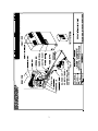
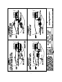
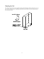
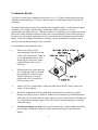
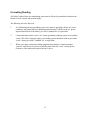
CABIN COMFORT
Self Contained Units
Installation, Operation & Maintenance Manual
Revised 3-15-04
L-2334
Table of Contents
Cabin Comfort Overview Diagram .....………………………………………….
3
Preface...................................................................................................................
4
Unpacking and Inspection ....................................................................................
5
Safety Considerations ...........................................................................................
5
Placement Recommendations ...............................................................................
5
Seawater Pump and Plumbing ..............................................................................
6
Seawater Pump Installation Diagram ……………………………………………
7
Mounting the Unit ................................................................................................
8
Condensate Drains ................................................................................................
9
Electrical ...............................................................................................................
10
Bonding/Grounding ..............................................................................................
11
Wiring Diagrams ………………………………………………………………..
12-14
Operating Instructions ..........................................................................................
15
Troubleshooting Guidelines .................................................................................
16-17
Maintenance .........................................................................................................
18
Limited Warranty ................................................................................................
19
This manual is intended to provide the information necessary to ensure proper installation,
operation, and maintenance of the Cabin Comfort Series units. Improper installation or
misunderstood operating procedures can result in unsatisfactory performance and/or premature
failure of these units. Before proceeding, read this manual completely. The Cabin Comfort
Series units are covered under the existing Dometic Corporation warranty policy contained in
this manual. In the interest of product improvement, specifications and design are subject to
change without prior notice.
NOTICE CLEAN AIR ACT AMENDMENTS OF 1990 [TITLE VI - SECTION 608(C-1)]
“Effective July 1, 1992, it shall be unlawful for any person, in the course of maintaining,
servicing, repairing, or disposing of an appliance or industrial process refrigeration, to knowingly
vent or otherwise knowingly release or dispose of any Class I* or Class II** substance used as a
refrigerant in such appliance (or industrial process refrigeration) in a manner which permits such
substance to enter the environment. De minimis releases associated with good faith attempts to
recapture and recycle or safely dispose of any such substances shall not be subject to the
prohibition set forth in the proceeding sentence.”
*Class I substances include CFC-12
**Class II substances include HCFC-22
2
3
Preface
Congratulations on the purchase of your Cabin Comfort air conditioner. No matter which of the
following features was the reason you purchased this unit, we are sure it will meet your needs
and will give you many years of efficient and trouble free use.
The Cabin Comfort Series units are self-contained, reverse cycle air conditioners. These units
are designed for marine applications incorporating the following features:
•
•
•
•
•
Cupro-nickel condenser coil
Raised lance fin designed evaporator coils
1-1/2" deep drain pan with multiple condensate drain locations
Pre-charged and pre-wired systems for easy connections
Charge guard protection system integrity during handling and installation
The controls included with this unit are designed specifically for the unique requirements of the
Cabin Comfort environmental control systems and their applications. The controller has been
designed with the flexibility and the following “user friendly” features customers require for their
applications.
•
•
•
•
Variable fan speed selection
On - Start - Run switch
Dependable mechanical thermostat
Pre-wired control cable
Marine Air Systems is a product of Dometic Corporation. Dometic is a recognized leader in
the design and manufacture of high-performance comfort control systems, refrigeration products
and battery charging products for demanding environments, including commercial and
recreational marine craft, vehicles and other applications. We offer an unparalleled scope of
products, dealer networks, applications support, engineering resources and production
capabilities throughout the world. Our team has many years of experience in the design,
manufacture, application and support of our products. Our practical experience and design
capability allows our application engineers and sales representatives to offer optimum solutions
for your environmental control requirements. Product lines also include well known Cruisair®,
Grunert®, and Sentry™.
Copyright 2004 Dometic Corporation, All Rights Reserved
Every precaution has been taken in the preparation of this manual to ensure its accuracy. However, Dometic
Corporation assumes no responsibility for errors and omissions. Neither is any liability assumed for damages
resulting from the use of this product and information contained herein.
4
Unpacking and Inspection
Move units in the normal “up” orientation as indicated by the arrows on each carton. When the
equipment is received all items should be carefully checked against the bill of lading to be sure
all cartons have been received. Examine units for shipping damage, removing the units from the
cartons if necessary. Units in question should also be internally inspected. If the unit is
damaged, the carrier should make the proper notation on the delivery receipt acknowledging the
damage.
Safety Considerations
Installation and servicing of this system can be hazardous due to system pressure and electrical
components. Only trained and qualified service personnel should install, repair, or service
equipment. Untrained personnel can perform basic functions of maintenance such as cleaning
coils and replacing filters.
Warning: Before performing service or maintenance operations on system, turn off main
power to unit. Electrical shock could cause personal injury or death.
When working on this equipment, always observe precautions described in the literature, tags,
and labels attached to the unit. Follow all safety codes. Wear safety glasses and work gloves and
place a fire extinguisher close to the work area.
Placement Recommendations
Since the Cabin Comfort Series is a self-contained unit, it can readily be used to cool any desired
area. However, the physical location of the air conditioner is an important factor to consider
prior to installing the unit. The unit should be installed in a central location in the room to be
cooled with adequate space around the unit for maintenance as well as a free flow of supply and
return air.
Regardless of which BTU size unit you are installing, make sure that the unit is positioned on a
firm, level, horizontal surface and that the condensate drain tube is able to run downward from
the unit to a suitable drain location. INSURE THAT THE SELECTED LOCATION IS
SEALED FROM DIRECT ACCESS TO BILGE VAPORS.
Selecting a good location for your air conditioner is the most important part of your preparations.
Be sure to consider the size of the area you are cooling, the air distribution needs, and the
physical size of the unit you have chosen. Then, plan all connections which must be made;
condensate drain, cooling water in and out, electrical connections, and pump placement, to assure
easy access for routing and servicing.
5
Seawater Pump and Plumbing
The seawater thru-hull inlet should be a minimum of 3/4" inside diameter (I.D.) for 1 or 2 units
or 1" I.D. for up to 5 units. It should be located as near to the keel as practical and utilizing a
speed scoop to insure positive water flow while the vessel is underway. A full flow bronze sea
cock should be used, so that you have the ability to disrupt the incoming water to the sea strainer
and circulator pump should the need arise.
Since the circulation pump is centrifugal and not self-priming, it must be mounted well below the
water line. It is, therefore, recommended that all hose type connections below the water line be
secured by means of double hose clamping. A sea strainer located between the sea cock and
pump is essential to protect the pump from foreign matter, such as seaweed. With the water
pump installed, a gradual incline should exist from the sea cock to the strainer to the pump.
Note: All pump warranties will be void unless a sea strainer is installed.
From the discharge outlet of the pump, route your plumbing to the lower hose connection at the
condenser coil. This hose should be plumbed with as few bends and restrictions as practical with
no loops or vertical bends so that they are self-draining and consequently self-purging. The
discharge outlet of the condenser must be plumbed overboard using a discharge thru-hull located
above the water line. The location selected for the overboard discharge thru-hull should be
accessible for periodic visual inspection. A 5/8" hose is required when plumbing from the pump
or manifold to the condenser coil and the overboard discharge thru-hull fitting. It is
recommended that reinforced hose be used as well as double hose clamping.
Since the seawater system has components mounted below the water line, a recap of the
installation is in order:
1.
2.
3.
4.
5.
6.
7.
8.
9.
Select a location of the speed scoop thru hull inlet as close to the keel as possible.
Bed the sea cock with a marine type sealant designed for underwater applications.
Install a bronze, full flow sea cock on the thru-hull
Use a sea strainer to protect the pump.
Mount the pump below the water line insuring that an incline exists between the sea cock and
the pump.
Double clamp all hose connections.
Maintain a minimum of 5/8" I.D. hose for the pump or manifold to the condenser.
Discharge the water through a hull-side thru-hull fitting above the water line, with access for
visual inspection.
No loops or vertical bends will insure self-draining and consequently self-purging.
See next page for seawater pump installation diagram.
6
7
Mounting the Unit
The Cabin Comfort Series unit is supplied with a painted aluminum cabinet which also serves as
an overflow condensate pan. Mounting clip brackets are provided to secure the base pan onto a
flat, horizontal surface.
8
Condensate Drains
The Cabin Comfort Series condensate drain pan is over 1-1/2" high with the largest drain pipe
available accommodating 5/8" I.D. hose, and assuring more than adequate drain off under all
conditions.
All Cabin Comfort Series units come complete with condensate drains. Under adverse climatic
conditions, (for example, high humidity), condensate could be produced at a rate of
approximately one gallon per hour. With this in mind, it is important to route condensate drains
downward, with a minimum amount of bends, and overboard through a thru-hull located above
the water line, utilizing all standard practices for securing the hose and mounting the thru-hull
fitting. After the condensate installation is complete, test the installation by pouring a cup of
water into the pan and checking for flow overboard.
For installation of the condensate drain:
•
Remove one of the desired
watertight plugs from the base pan
of the Cabin Comfort unit. Note: It
is recommended that the most aft
facing plug be removed to ensure
proper drainage as the vessel is
underway.
•
Slip the liquid-seal washer onto the
PVC fitting and connect it through
the exposed hole in the base pan
with the locking nut. Securely
tighten with two (2) wrenches to
provide a proper seal.
•
Attach a 5/8" I.D. reinforced hose to the hose barb end of the PVC fitting with a hose
clamp. Securely tighten.
•
Install the condensation drain downhill from the unit and aft is possible to a proper
drainage area (bilge, sump, overboard). Note: Do not terminate any condensation drain
within four (4) feet of the outlet of engine exhaust systems, on the exterior of the hull, nor
in a compartment housing an engine, unless the drain is connected properly to a sealed
condensate pump.
•
If dual drain fittings are used: These may be connected to a single condensation drain,
provided that a minimum 2"drop exists from the base pan drains to the connection
fittings.
9
Electrical
Prior to making any decisions concerning the electrical source, please refer to your specifications
sheet on your boat and note the total amperage draw to operate the necessary air conditioning
system. With this information at hand, now consider the following possibilities:
1.
Generally speaking most boats come standard with a single 30 amp shore line connection.
2.
Unless the boat is equipped with such electrical items that require substantial electrical
supply (such as electric stove, water heater, refrigerator/freezer, etc...) the air conditioning
system may be wired to this existing 30 amp, 115 volt service, as long as the total
requirement does not exceed 30 amp. In such cases where there are these accessories that
draw high amperage, it is recommended that an additional 30 amp shore line service be
installed to handle the additional electrical load that the air conditioning system will
require.
All Cabin Comfort Series units are supplied with a 5 position terminal strip mounted on top of
the electrical box. The electrical supply, ground wires, and pump circuits are all connected at
this terminal strip. Electrical supply to the unit is connected to the terminals marked POWER
(115 or 230 Volt). The wiring from the seawater pump is connected to the terminals marked
PUMP.
NOTE: If you use two or more units on the same seawater pump, the pump wires will be
connected to the pump relay panel to energize the pump. You will need another source of 115 or
230 volt power to run the pump. The pump relay panel should have its own circuit breaker.
Please see the wiring diagram furnished with the relay panel in this instance.
Note: Field wiring must comply with ABYC electrical codes. Power to the unit must be
within the operating voltage range indicated on the nameplate. Properly sized fuses or
HACR circuit breakers must be installed for branch circuit protection. See equipment
rating plate for maximum size.
10
Grounding/Bonding
All Cabin Comfort Series air conditioning units must be effectively grounded to minimize the
hazard of electric shock and personal injury.
The following are to be observed:
1.
AC (alternating current) grounding (green wire) must be provided with the AC power
conductors and connected to the ground terminal (marked “GRND) at the AC power
input terminal block of the unit(s), per ABYC standard E-8, or equivalent.
2.
Connections between the vessel’s AC system grounding conductor (green wire) and the
vessel’s DC (Direct Current) negative or bonding system should be made as part of the
vessel’s wiring, per ABYC standard E-9, or equivalent.
3.
When servicing or replacing existing equipment that contains a chassis-mounted
“ground” stud, the service person or installer must check the vessel’s wiring for the
existence of the connection required in item 2 above.
11
12
13
14
Operating Instructions
The Cabin Comfort MCP has three basic controls:
•
•
•
System Switch
Fan Speed Switch
Thermostat
Follow these procedures for operation of the system:
1.
2.
3.
4.
5.
6.
7.
8.
9.
10.
Set the MCP System switch to “OFF”.
Set the circuit breaker on the ship’s main control panel to “ON”.
Turn the Thermostat fully clockwise for cooling and fully counter-clockwise for heating.
Set the fan speed control on “HIGH” position (fully clockwise).
Be certain the seawater inlet valve is open.
Turn the System switch to “START”. This energizes the fans and the seawater pump.
Check the overboard discharge to be sure that water is flowing from the overboard thruhull outlet.
Turn the system switch knob to “RUN”. The compressor will start to cool or heat
according to the setting of the thermostat.
To set the thermostat, allow sufficient time for the unit to operate to heat or cool the area
to the desired temperature. When the area is sufficiently heated or cooled, turn the
thermostat know slowly to the center position until it ‘clicks’ once. The thermostat is
now set to maintain a constant temperature.
On the cooling cycle, use any fan speed desired. When operating in the heat cycle, set the
fan speed control to the “HIGH” position. Decrease the fan to medium setting and run
the system in this position for the most efficient heat output.
Note: If ambient temperatures are less than 50°F (10°C), allow the unit to run on low for 5
to 10 minutes, until it begins to heat well.
Keep in mind, however, that the lower the fan speed, the less capacity the system has.
To turn the system off, turn the System switch on the control panel to “OFF”.
The thermostat on the MCP control panel serves to cycle the compressor on and off and provide
an automatic changeover from cooling to heating with a 3.5°F (1.9°C) differential. Rotating the
thermostat to the left after it has been set for cooling will cause the unit to heat. If you rotate the
thermostat to the right, the unit will cool. If the thermostat is left stationary after being set, the
unit will cycle from cooling to neutral, or heating to neutral depending on the requirement.
15
Troubleshooting Guidelines
FAULT
Nothing works
at all
Fan runs but no
water flow
Fan and Pump
run, but no
cooling or
heating
Compressor not
running or
trying to start
POSSIBLE
REASON
Air conditioner
circuit breaker is off.
Wiring at terminal
strip is incorrectly
wired
Water intake valve is
closed
Strainer or intake is
plugged
Hose collapsed,
kinked or pinched
Pump relay panel
may not be operating
properly
Selector switch may
not be in “Run”
position, but rather
in “Start” mode
Thermostat may not
be set properly, thus
not signaling
compressor to start.
Wiring terminal to
thermostat or
selector switch may
be disconnected.
CORRECTION
Turn circuit breaker on at ship’s panel.
Check wiring diagram; correct if necessary
Open valve
Clean strainer/intake
Repair/reroute hose
Check pump relay panel wiring diagram. With unit
breakers and A/C pump breaker on, check input
voltage to relay panel. If voltage is not present, a
wiring problem exists back to the ship’s panel. With
unit on, check voltage at signal terminals (1A & 1B,
2A & 2B, etc.) If voltage is not present, a wiring
problem exists back to the unit. With voltage present
at both locations above, check output terminals to
seawater pump. If voltage is not present, either:
1. Signal circuit is defective. Move to a spare circuit if
available.
2. Triac is defective on seawater pump circuit.
Replace circuit board if above does not correct problem
Verify switch setting
Turn counter-clockwise for warmer and clockwise for
cooler
Check wiring schematic before reconnecting loose
terminals.
16
Troubleshooting Guidelines (continued)
FAULT
Fan and Pump run,
but no cooling or
heating
Compressor
operates for only
short periods of
time.
POSSIBLE REASON
Seawater intake valve may be closed.
CORRECTION
Open valve
Seawater strainer or intakes could be
plugged.
Check hoses from intake to pump,
pump to condensing unit, and
condensing unit to overboard to
make certain that they have not
collapsed, pinched, or kinked.
Check voltage to pump, check
pump head and impeller.
Clean filter
Turn counter-clockwise for
warmer and clockwise for cooler
Give system time to stabilize.
Verify seawater temperature.
Water pump may be defective.
Fan blows, Pump &
Compressor runs,
but unit does not
heat or cool
enough.
Dirty return air filter
Check for proper thermostat setting
On heat setting, system takes fifteen
minutes to stabilize. As the seawater
becomes colder, the output of the
system is reduced. Note that 45°F
(7.2°C) seawater is the coldest
recommended operating level.
On cooling, the thermostat may be set
too cold or supply air may be short
cycling causing the evaporator coil to
freeze
Low voltage can cause the air
conditioning system to cycle off
before proper temperature is reached
Reduced water flow
17
Check thermostat setting and/or
redirect supply air so that it is not
directed into the return air stream.
Switch unit into heat until the ice
melts. A unit low on refrigerant
charge will cause evaporator icing.
Check electrical supply source
Visually check water flow
overboard and if low take
corrective action
Maintenance
Winterization
There are several methods of winterization, some of which work better than others. The four
various methods employed are:
1. Use of pressurized air to force water to be discharged through the overboard thru-hull fitting.
2. Use of the seawater pump to pump anti-freeze solution through the system and discharging
through the overboard thru-hull fitting.
3. Use of pressurized air injected at the overboard discharge fitting and the water being
discharged through the seawater intake fitting.
4. Pumping of anti-freeze solution into the overboard thru-hull fitting, and discharging through
the intake thru-hull fitting.
Since our systems are designed to be self-purging, a method which causes the anti-freeze solution
to flow downward is the method of choice. By this means, the anti-freeze solution will displace
any water trapped and eliminate the possibility of freezing in hidden areas. In addition, when the
system is utilizing a magnetically driven impeller, the impeller should be removed from the wet
end assembly, wiped with an alcohol solution, and stored in a warm, dry area until
commissioning takes place.
For the purpose of protecting the environment, collect all discharged liquids via a suitable
containment vessel. Recycle the anti-freeze solution after having tested and it is determined that
it meets the freeze protection parameters required in your specific area for freeze protection.
Dispose of unusable anti-freeze properly.
Seawater Strainer
Marine Air Systems recommends the use of a suitable seawater strainer in all seawater circuits.
This seawater strainer, when installed before the seawater circulation pump protects the pump
from contaminants and premature failure from these contaminants. Insure that your seawater
pump receives adequate seawater by periodically cleaning the sea strainer basket. Seawater
systems installed without a seawater strainer device of the proper size or no seawater strainer, are
not in compliance with Marine Air Systems’ recommended installation practices. This noncompliance will void the warranty on the Marine Air Systems’ components installed in that
particular application.
Return Air Filters
The purpose of the return air filter is to remove debris from the air prior to the air being drawn
across the evaporator coil and fins. Dust and lint can clog and reduce air flow across the
evaporator coil and result in poor performance of the air conditioning unit. Restricted air flow
may cause head pressures to rise and even cause excessively higher amperage, which may
ultimately result in activation of the protection device which will prevent further damage. To
clean the filter, remove the filter from the return air grill, rinse with water, air dry, and reinstall.
18
Manufacturers Limited Warranty Agreement
The following warranty is extended to cover products manufactured or supplied by Dometic
Corporation, and is subject to qualifications indicated.
Dometic Corporation warrants for the periods set forth below that products manufactured or
supplied by it will be free from defects in workmanship and material, provided such products are
installed, operated, and maintained in accordance with Dometic Corporation’ written instruction.
ALL IMPLIED WARRANTIES INCLUDING MERCHANTABILITY AND FITNESS FOR A
PARTICULAR PURPOSE, ARE LIMITED TO THE TERMS AND PERIODS OF WARRANTY SET
FORTH BELOW AND, TO THE EXTENT PERMITTED BY LAW, ANY AND ALL IMPLIED
WARRANTIES ARE EXCLUDED.
Components comprising a complete system on a new installation are warranted for a period of
one (1) year from the date of installation, but not to exceed twenty-four (24) months from the
date of shipment from the Dometic Corporation factory. Costs which exceed the limited
schedule of allowances, i.e., parts, labor, limited travel allowance, removal and reinstallation are
covered for the same period of time and are the responsibility of the customer.
Dometic Corporation will repair, or replace at its option, components found to be defective
due to faulty materials or workmanship, when such components, examined by an authorized
service dealer or a factory service representative, are found to have a defect for which the
company is responsible. In addition, Dometic Corporation will pay labor costs as outlined in its
Schedule of Limited Warranty Allowances for removal and re-installation of such
components. Refer to Manufacturer’s Limited Warranty Policy for complete coverage and
exclusions. Replacement components are warranted for the duration of the remaining warranty
period in effect on the original component.
This limited warranty is extended in lieu of all other warranties, agreements or obligations,
expressed or implied, concerning Dometic Corporation’s components. This warranty shall be
governed by the laws of the State of Florida and gives the original first end user definite legal
rights.
This warrant does not cover damages incidental and or consequential to the failure of Dometic
Corporation’s equipment including but not limited to; normal wear, accident, misuse, abuse,
negligence or improper installation, lack of reasonable and necessary maintenance, alteration,
civil disturbance or act of God.
No person or dealer is authorized to extend any other warranties or to assume any other liabilities
on Dometic Corporation’s behalf, unless made or assumed in writing by an officer of Dometic
Corporation.
19
Dometic Corporation
Environmental Systems
2000 N. Andrews Ave. Ext. • Pompano Beach, FL 33069-1497 USA
Phone: 954-973-2477 • Facsimile: 954-979-4414
Fleets Industrial Estate • 26 Willis Way • Poole, Dorset BH15 3SU, England
Phone: +44(0)870 3306101 • Facsimile: +44(0)870 3306102
Website: www.marineair.com • Email: [email protected]