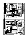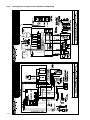
1
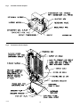
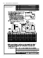
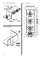
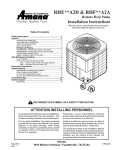
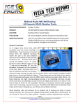
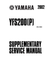
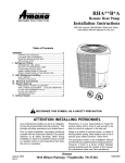
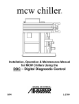
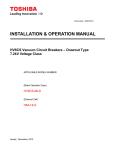
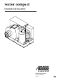
vector compact
Installation & Operation
Direct Expansion Systems
Revised: 20140321
L-2254
Table of Contents
Table of Contents
IF YOU HAVE A DIGITAL CONTROL...........................................................................................................3
Introduction How It Works................................................................................................................................................4
Installation
Unpacking and Inspection............................................................................................................................5
Safety Considerations..................................................................................................................................5
Placement of System....................................................................................................................................5
Condensate Drains.......................................................................................................................................6
Blower Assembly..........................................................................................................................................6
Mounting Brackets........................................................................................................................................6
Supply & Return Air Grilles and Transition Boxes.........................................................................................6
Ducting.........................................................................................................................................................6
Seawater Pump and Plumbing.....................................................................................................................7
Electrical Connections, Grounding and Bonding..........................................................................................8
Manual Control Panel (MCP) Installation.....................................................................................................8
Installation Checklist (Review prior to installation)........................................................................................9
Operation
Mechanical Control Panel (MCP) Operation.............................................................................................. 10
Quick Start Operations Checklist............................................................................................................... 10
Troubleshooting General Troubleshooting ........................................................................................................................... 11
Digital Controls Troubleshooting ................................................................................................................ 12
MCP Mechanical Control Panel Troubleshooting ....................................................................................... 14
Maintenance
Winterization............................................................................................................................................... 15
Manufacturers Limited Warranty Agreement
16
Description of Figures
17
Distributor Listing
27
IF YOU HAVE A DIGITAL CONTROL
Copyright 2005 Dometic Environmental Corporation, All Rights Reserved - Every precaution has been taken in the preparation of this manual to insure its accuracy. However, Dometic assumes
no responsibility for errors or omissions. Neither is any liability assumed for damages resulting from the use of this product and information contained herein.
L-2254
3
❖ English
Introduction
any such substances shall not be subject to the prohibition
set forth in the proceeding sentence.”
* Class I substances include CFC-12
** Class II substances include HCFC-22
Congratulations on the purchase of your Marine Air Systems’ Vector Compact® air conditioner. No matter which of
the following features was the reason for your purchase of
this air conditioner, we are sure it will meet your needs and
will give you many years of efficient and trouble free use.
The Vector Compact self-contained direct expansion air
conditioners are designed for marine applications incorporating the following features:
Marine Air Systems
Marine Air Systems (MAS) is a product of Dometic Environmental Corporation. Dometic is a recognized leader in
the design and manufacture of high-performance comfort
control systems, refrigeration products and battery charging
products for demanding environments, including commercial and recreational marine craft, vehicles and other applications. We offer an unparalleled scope of products, dealer
networks, applications support, engineering resources and
production capabilities throughout the world. Our team has
many years of experience in the design, manufacture, application and support of our products. Our practical experience and design capability allows our application engineers
and sales representatives to offer optimum solutions for
your environmental control requirements. Product lines also
include well known Cruisair, Grunert, and Sentry.
•Patented compact design with the condenser coil in
the evaporator shroud
• High efficiency rotary compressor or scroll (24K) compressors
• Cupronickel condenser coil
• Enhanced fin designed evaporator coil
• 2” deep drain pan with multiple condensate drain locations
• Anti-vibration base pad
• Pre-charged and pre-wired systems for easy
connections
• Rotatable blower assembly
How It Works
• Charge Guard® ensures environmental protection and
system integrity
Your self-contained air conditioner consists of four main
components and a refrigerant gas circulating through the
system. The BLOWER draws warm cabin air across the
fins on the EVAPORATOR where the heat from the air is
transferred to the refrigerant in the evaporator coil. As the
refrigerant evaporates from a liquid into a gas it absorbs
the heat from the cabin air. The COMPRESSOR then
compresses the refrigerant gas and pumps it through the
outer tube in the CONDENSER COIL. The seawater pump
circulates cool seawater through the inner tube in the condenser coil, this cools the refrigerant and condenses it into
a liquid. The heat from the refrigerant is exchanged to the
seawater and discharged overboard. The liquid refrigerant
is then passed through the EVAPORATOR COIL and the
cycle repeats. Removing heat from the cabin air lowers its
temperature. The cooled air is blown through the ducting
and out the supply air grille(s). For reverse cycle heating,
the refrigerant flows in the opposite direction through the
reversing valve. Heat is transferred from the seawater in the
condenser coil to the refrigerant and then to the air blowing
through the evaporator into the cabin. Seawater temperature will directly affect the a/c unit’s efficiency. This a/c unit
can effectively cool your boat in water temperatures up to
90°F and heat in water temperatures as low as 40°F. See
Figure 1.
This manual is intended to provide the information necessary to ensure proper installation, operation, and maintenance of the unit. The figures that are referenced throughout this manual can be found immediately after the warranty section. Improper installation or misunderstood operating
procedures can result in unsatisfactory performance and/
or premature failure of these units, so before proceeding
please read this manual completely.
The Vector Compact units are covered under the existing
Dometic Environmental Corporation (Dometic) warranty
policy contained in this manual. In the interest of product
improvement, Dometic’s specifications and design are subject to change without prior notice.
Clean Air Act Amendments of 1990
[Title VI - Section 608(C-1)]
“Effective July 1, 1992, it shall be unlawful for any person,
in the course of maintaining, servicing, repairing, or disposing of an appliance or industrial process refrigeration, to
knowingly vent or otherwise knowingly release or dispose
of any Class I* or Class II** substance used as a refrigerant in such appliance (or industrial process refrigeration)
in a manner which permits such substance to enter the
environment. De minimis releases associated with good
faith attempts to recapture and recycle or safely dispose of
L-2254 Introduction
4
❖ English
Installation
Unpacking and Inspection
This component is charged with hydrochloro-fluorocarbon
(HCFC) refrigerant R22. Effective July 1, 1992 it shall be
unlawful for any person to knowingly vent or otherwise
knowingly release any class 1 (CFC) or class 2 (HCFC)
substance as a refrigerant in a manner which permits such
substance to enter the atmosphere per the clean air act of
1990. Public law 101-549 Title IV Section 608-C. Failure to
comply may result in severe penalties, including fines and
imprisonment.
When the equipment is received, all items should be carefully checked against the packing list to ensure all cartons
have been received. Move units in the normal “up” orientation as indicated by the arrows on each carton. Examine
cartons for shipping damage, removing the units from the
cartons if necessary. If the unit is damaged, the carrier
should make the proper notation on the delivery receipt
acknowledging the damage.
CAUTION: When unpacking and installing the 3‑knob control (if mechanical option is used), care must be taken not
to kink or break the copper cap tube when uncoiling the
sensing bulb. The cap tube is hollow and kinking or sharp
bends will inhibit system operation.
Warning
To minimize the hazard of electrical shock and
personal injury, this component must be effectively
grounded. Refer to the installation guidelines for
further information.
Safety Considerations
Caution
VERY IMPORTANT: Never install your air conditioner in
the bilge or engine room areas. Insure that the selected location is sealed from direct access to bilge and/
or engine room vapors. Do not terminate condensate
drain line within three (3) feet of any outlet of engine
or generator exhaust systems, nor in a compartment
housing an engine or generator, nor in a bilge, unless
the drain is connected properly to a sealed condensate
or shower sump pump.
High compressor temperature is normal.
Do not touch.
Placement of System
Selecting a good location for your air conditioner is the
most important part of your preparations. Be sure to consider the size of the area you are cooling, the air distribution needs, and the size of the unit you have chosen.
Keeping in mind that cool air has a tendency to fall, it is
highly recommended that you locate the supply air grille as
high as possible in the cabin. See Figures 2 and 3.
Installation and servicing of this system can be hazardous
due to system pressure and electrical components. When
working on this equipment, always observe precautions
described in the literature, tags and labels attached to the
unit. Follow all safety codes. Wear safety glasses and work
gloves and place a fire extinguisher close to the work area.
The following is a summary of the labels on the unit:
The Vector Compact unit should be installed as low as
possible, BUT NEVER IN THE BILGE OR ENGINE ROOM
AREAS. INSURE THAT THE SELECTED LOCATION IS
SEALED FROM DIRECT ACCESS TO BILGE AND/OR
ENGINE ROOM VAPORS. Installing the unit as low as
possible (such as under a V-berth, dinette seat or bottom
of a locker) and ducting the supply air as high as possible,
creates an ideal airflow condition. This type of installation
will prevent short or premature cycling.
Danger
Electrical shock hazard. Disconnect voltage at main
panel or power source before opening any cover.
Failure to comply may result in injury or death.
The unit should be positioned on a firm, level, horizontal
surface and the condensate drain line should run downward from the unit to a suitable drain location. Plan all connections which must be made including ducting, condensate drain, seawater in and out, electrical power connections, location of control, and seawater pump placement, to
assure easy access for routing and servicing.
Warning
This component does not meet federal requirements for ignition protection. Do not install in
spaces containing gasoline engines, tanks, LPG/
CPG cylinders, regulators, valves or fuel line fittings.
Failure to comply may result in injury or death.
Notice
L-2254 Installation
5
❖ English
Minimum Tools Required
water from standing in the pan. See item 7 for instructions
on connecting two drain lines.
• Screws drivers
IMPORTANT! Do not terminate condensate drain line
within three (3) feet of any outlet of engine or generator
exhaust systems, nor in a compartment housing an engine
or generator, nor in a bilge, unless the drain is connected
properly to a sealed condensate or shower sump pump.
• Pliers
• Pipe wrenches
• Wire cutters/crimpers
• Drill and assorted bits
• Jig saw
Blower Assembly
• Duct tape
With the Vector Compact you can achieve multi-directional
supply air discharge from a single unit by rotating the blower to the desired location. It is ideal for tight installations
as 130° of rotation are available with which to position the
blower. Its advanced design allows the blower to be easily
removed for rotating or servicing by removing the two
mounting ring screws and the screws attaching the blower
to the drain pan. Rotate the blower to allow the most direct
flow of air to the supply air grille. Reinstall the mounting
screws. Plug any unused screw holes in the blower to
prevent air loss.
• Electrical tape
• Threaded seal tape
• Beding compound to seal thru hull fittings
• Hardware to secure unit, pump, strainer, grilles & control panel
Condensate Drains
The condensate drain pan is 2” high with up to four drain
locations. During conditions of high humidity, condensate
may be produced at a rate of approximately 1/2 gallon per
hour. With this in mind, it is important to route condensate
drains downward to a sump pump. It is not recommended
to route condensate drains to the bilge. After the condensate drain installation is complete, test the installation by
pouring a quart of water into the pan and checking for
good flow. See Figure 4.
Mounting Brackets
The a/c unit is supplied with a base pan that also serves
as a condensate pan. Mounting clip brackets are provided
to secure the base pan onto a flat, horizontal surface. See
Figure 5.
Supply & Return Air Grilles
and Transition Boxes
For installation of the condensate drain:
Install the supply air grille as high as possible in a location that will provide uniform air distribution throughout the
cabin, grille louvers should be directed upward. The return
air grille should be installed as low and close to the a/c
unit as possible to insure direct uninterrupted airflow to the
evaporator. The return air grille should have a minimum
four inches (4”) of clearance in front of it, free from any furniture or other obstructions. In no instance should a supply
air discharge be directed towards a return air grille, as this
will cause the system to short cycle. Allow for adequate
clearance behind the supply air grille(s) for the transition
box and ducting connection. The table in Figure 8 shows
minimum grille sizes. See the MAINTENANCE section of
this manual for return air filter cleaning instructions.
1. Remove the aft facing watertight plug from the base pan
of the a/c unit (see note).
2. Slip the solid washer and the liquid-seal washer onto the
PVC fitting in that order.
3. Connect the fitting through the exposed hole in the base
pan with the locking nut.
4. Securely tighten with two (2) wrenches to provide a
proper seal.
5. Attach a 5/8” I.D. reinforced hose to the hose barb and
secure with stainless steel hose clamps.
6. Install the condensate drain hose downhill from the unit
and aft to a sump.
Ducting
7. Two drain fittings may be used and the hoses teed
together provided there is a minimum 2” drop form the
bottom of the base pan to the tee connection.
Good airflow is critical for the performance of the
entire system. It is highly dependent on the quality
of the ducting installation. The ducting should be run
as straight, smooth and taut as possible minimizing the
number of 90° bends (two tight 90° bends can reduce
airflow by 25%). The table in Figure 8 shows minimum duct
diameters and their corresponding supply and return air
grille minimum area in square inches. If a transition box is
used, the total area of supply air ducts going out of the box
should at least equal the area of the supply duct feeding
Note: The reason to use the “aft facing” drain location is so
that water will tend to drain out of the pan when the vessel
is under way. However, the boat owner should inspect the
pan when the vessel is at rest. If water is collecting in the
pan along an edge other than “aft facing”, then the drain on
that edge should also be utilized. This will help to prevent
L-2254 Installation
6
❖ English
The speed scoop intake must face forward and not be
shared with any other pump. A seawater strainer is mandatory between the shut off valve (seacock) and the pump
to protect the pump from any foreign matter. Failure to
install a seawater strainer will void the pump warranty.
The seawater system should be installed with an upward
incline from the speed scoop & seacock, through the
strainer, to the inlet of the pump and then up to the inlet
of the a/c unit’s condenser coil. The discharge from the a/c
unit should then run to the seawater outlet thru-hull fitting
which should be located where it can be visually checked
for water flow and as close as practicable to the waterline
to reduce noise. All hose connections shall be secured by
means of double/reversed stainless steel hose clamps. Use
threaded seal tape on all threaded connections. The following is a summary of the seawater system installation:
the box. To calculate the square inch area of a round duct,
multiply the radius by itself (r2) and multiply that number by
3.1416(π). See Figure 8.
The following is a summary of proper ducting connections:
1. Pull back the fiberglass insulation exposing the inner
mylar duct hose.
2. Slide the mylar duct hose around the mount ring until it
bottoms out.
3. Screw 3 or 4 stainless steel sheet metal screws through
the duct hose into the transition ring.
Make sure to catch the wire in the duct hose with the
heads of the screws. Do not use band clamps, as the
hose will slide off.
1. Install the speed scoop thru-hull inlet as close to the
keel and as far below the water line as possible, facing
forward. Bed the scoop with a marine sealant designed
for underwater use.
4. Wrap duct tape around the ducting and ring joint to prevent any air leaks.
5. Pull the insulation back up over the mylar to the ring and
tape this joint.
2. Install a bronze, full flow seacock on the speed scoop
thru-hull inlet.
6. Remove excess ducting and use the same connection
method at the supply air grille.
3. Install a seawater strainer below the level of the pump
with access to filter.
All ducting should:
• Be appropriately sized for each application.
4. Mount the pump above the strainer and at least one foot
below the waterline.
• Run as smoothly and taut as possible.
5. Connect the seacock and strainer with an uphill run of
reinforced marine grade hose.
• Have as few bends or loops as possible.
• Be securely fastened to prevent sagging during boat
operation.
6. Connect the discharge from the pump uphill to the bottom inlet of the a/c unit’s condenser coil with 5/8” hose.
Connect the discharge from the condenser coil to the
overboard discharge thru-hull fitting with 5/8” hose.
• Have all excess ducting lengths trimmed off.
• Not be flattened or kinked.
• Insulated when located in high heat load areas (hull
side, mechanical compartments, etc.).
7. Avoid loops, high spots or the use of 90° elbows with
seawater hose (each 90° elbow is equivalent to 2.5’ of
hose and a 90° elbow on the pump outlet is equivalent to
20’ of hose).
• Be properly protected against potential damage when
routed through open areas.
8. Double clamp all hose connections with stainless steel
clamps, reversing the clamps.
Seawater Pump and Plumbing
9. Use threaded seal tape on all threaded connections.
Several guidelines should be followed during the installation of the seawater system. Since the circulation pump is
centrifugal and not self-priming, it must be mounted so that
it is always at least one foot below the water line regardless of which tack the vessel is on. Pump may be mounted horizontally or vertically, however the discharge must
always be above the inlet. Pump head should be rotated
toward the direction of water flow. Install the seawater
speed scoop intake as far below the water line and as
close to the keel as possible in any application, but
especially on a sailboat, to keep the intake in the water
when the boat heels over so that air does not get into
the system. (See Figure 7 for proper installation.)
L-2254 Installation
10. Connect all metallic parts in contact with seawater
to the vessel’s bonding system including the speed
scoop inlet, strainer, pump and the air conditioner.
Failure to do so will void warranty.
Electrical Connections, Grounding
and Bonding
All a/c units have a terminal strip mounted inside the
electric box. The terminal strip is labeled for proper connections of the electrical supply, ground wires and pump
circuits. A wiring diagram is provided in the electrical box
and in this manual. The wiring diagram in the electrical box
supersedes the one in this manual and ABYC standards.
7
❖ English
vessels bonding system also. This will help eliminate any
possibility of corrosion due to stray current or voltage.
The correct size circuit breaker should be used to protect
the system as specified on the a/c unit’s data plate label. A
minimum of 12 AWG boat cable should be used to supply
power to the a/c unit and the seawater pump. All connections shall be made with ring or captive fork terminals. Turn
off a/c power supply circuit breaker before opening
electric box. See Figures 9 and 10.
FAILURE TO PROPERLY GROUND AND BOND THE SYSTEM WILL VOID WARRANTY!
3 Phase Notice
It is extremely important to insure that wiring and phase
sequencing of a three phase power source is correct.
Marine wiring standards call for power source phases L1,
L2, and L3 to be color-coded BLACK, WHITE, and RED,
respectively. These must be connected to the unit with the
proper sequence, otherwise, it will not operate properly.
If the wiring sequence is incorrect, the unit’s compressor
(Scroll type only) and pump (if applicable) will run in the
reverse direction at a significantly increased noise level.
Each a/c unit installed requires its own dedicated circuit
breaker. If there is only one a/c unit installed, the seawater
pump does not require a circuit breaker; the wiring from
the seawater pump is connected to the terminal strip in the
electric box. If two or more a/c units use the same seawater pump, the pump wires will be connected to a pump relay panel (PRP) which in turn has its own dedicated circuit
breaker sized for the pump (20 amp max). Please see the
wiring diagram furnished with the PRP (NOTE: PRP triac
must have its mounting screw installed in order to dissipate
heat). Electrical connections in the bilge and/or below the
waterline should use heat shrink type butt splices.
Manual Control Panel (MCP)
Installation
The MCP should be located within cap tube length of the
a/c unit. The 3 knob MCP is configured either vertically
(shown) or horizontally. The cut out size is 2.5” by 7.0”, see
MCP (Figure 6) for orientation. Once the cut out is made,
carefully uncoil the copper cap tube with return air sensor
(copper bulb) and route the control wires and cap tube
through the hole and back to the a/c unit using caution
not to kink the cap tube. Mount the return air sensor into
the clips provided with the Vector Compact unit. If the return air sensor cannot be mounted on the evaporator coil,
mount it behind the return air grille. The sensor must be
mounted in the return air stream. Make electrical connections according to the wiring diagram found in the electric
box and/or in this manual. See Figure 9.
Field wiring must comply with ABYC electrical codes. Power
to the unit must be within the operating voltage range
indicated on the data plate. Properly sized fuses or HACR
circuit breakers must be installed for branch circuit protection. See data plate for maximum fuse/circuit breaker size
(mfs) and minimum circuit ampacity (mca). All units must
be effectively grounded to minimize the hazard of electrical
shock and personal injury.
The following are to be observed:
1. AC (alternating current) grounding (green wire) must be
provided with the AC power conductors and connected
to the ground terminal (marked “GRND”) at the AC power input terminal block of the unit(s), per ABYC standard
E-8, or equivalent.
2. Connections between the vessel’s AC system grounding conductor (green wire) and the vessel’s DC (Direct
Current) negative or bonding system should be made
as part of the vessel’s wiring, per ABYC standard E-9, or
equivalent.
Installation Checklist
3. When servicing or replacing existing equipment that
contains a chassis-mounted ground stud, the service
person or installer must check the vessel’s wiring for the
existence of the connection required in item 2 above.
(Review prior to installation)
Note: Refer to the Elite and Passport I/O manuals
for installation and operation of those digital controls.
ABYC standards are available from:
American Boat and Yacht Council
3069 Solomons Island Rd.
Edgewater, MD 21036
Telephone: (410) 956-1050
Seawater Cooling System
❑ Speed scoop located as far below the water line and as
close to the keel as possible
❑ Shut off valve (sea cock) and speed scoop properly
sealed and tight
The a/c unit must be connected to the ship’s bonding
system to prevent corrosion due to stray electrical
current or voltage. All pumps, metallic valves and fittings
in the seawater circuit that are isolated from the a/c unit by
PVC or rubber hoses must be individually bonded to the
L-2254 Installation
8
❖ English
❑ Seawater pump is at least one foot below water line and
securely mounted
Grilles and Ducting
❑ Strainer mounted below pump with access to filter
❑ Return air grille mounted as low and as close to the a/c
unit as possible
❑ Supply air grille mounted as high as possible
❑ Double/reversed stainless steel hose clamps on all hose
connections
❑ Return air grille mounted away from bilge vapors or
exhaust fumes
❑ Threaded seal tape on all threaded connections
❑ Ducting is pulled taut, straight, smooth and properly
connected with no excess
❑ Hose runs uphill from speed scoop and sea cock to
strainer, pump and a/c unit, then downhill (if possible)
from a/c unit to overboard discharge
❑ Water flowing freely from overboard discharge while
pump is running
❑ Pump relay panel, if used, must have its own circuit
breaker sized for the pump (20 amp max)
❑ All metal fittings should be bonded
Mounting
❑ Not in engine room or bilge areas, must be sealed away
from exhaust or fumes
❑ Proper spacing allowed around unit
❑ Attached to solid level platform with hold down clips
provided
❑ Condensate drain routed aft and down hill to a sealed
sump (not bilge)
❑ Blower rotated toward supply air grille
Electrical
❑ The wiring diagram is located in the electrical box. If that
diagram is damaged or if you need a copy, please call
Dometic with the unit part number, serial number, and
wiring diagram number, all of which are located on the
unit data plate.
❑ All butt connections on pumps wire tightly crimped and
heat shrunk
❑ AC power source installed and grounded/bonded in
accordance with ABYC standards
❑ Control wires connected to terminal strip with captive
fork or ring terminals
❑ Circuit breakers sized according to specifications on the
data plate label
❑ Digital display cable is connected at both ends
❑ Pump Relay Panel (if used) has a dedicated circuit
breaker sized for the pump but not to exceed 20 amps
maximum.
L-2254 Installation
9
❖ English
Operation
Mechanical Control Panel
(MCP) Operation
Note: Do not turn the unit off and immediately turn it
back on. Wait at least 30 seconds.
Quick Start Operations Checklist
Note: Do not turn the unit off and immediately turn it
back on. Allow at least 30 seconds for refrigerant
pressure equalization.
L-2254 Operation
10
❖ English
Troubleshooting
General Troubleshooting
Fault: Low airflow.
Fault: Will not start.
Possible Reason/Correction
Possible Reason/Correction
1.Airflow is blocked.
1.A/C circuit breaker is off.
2.Fan Coil is iced.
2. Control is not turned on.
Fault: Fan coil is iced.
3. Wrong wiring at terminal strip.
Possible Reason/Correction
4. Push-on butt connectors became
disconnected during installation.
1. Thermostat set point is too low.
2. Improper airflow.
5. Input line voltage is insufficient.
3.Supply air is short-cycling.
Fault: Fan is not running.
4. Humidity level too high.
Check specific control troubleshooting section
5. When all else fails.
Fault: No cooling or heating.
Possible Reason/Correction
Fault: Water coil is iced in the heating
mode.
1. Temperature set point is satisfied.
Seawater temperature is below 40°F.
2.Obstructed seawater flow.
Fault: System runs continuously.
3.Seawater pump may be air-locked.
Possible Reason/Correction
Loss refrigerant gas.
5.Seawater temperature too high for cooling or too
low for heating.
1.Set point temperature is improperly set: too low
for cooling or too high for heating.
Fan coil is iced (in cooling).
2. Porthole or hatches open.
7.Fan is not running.
3.Seawater temperature too high for cooling or to
low for heating.
8.Seawater plumbing is air-locked.
4. Improper air sensor location.
9. Digital control is programmed for Cool or Heat
only, or mechanical control thermostat is rotated
to far towards either Cooler or Warmer setting.
Digital Controls Troubleshooting
10. High pressure switch open (in cooling) due to
improper seawater flow.
Fault: Digital display panel is not lit.
11. High pressure switch open (in heating) due to
improper airflow.
Possible Reason/Correction
1. 8-pin display cable plugs are not making contact
(unplugged, dirty, bent, or broken pins).
12. High-pressure switch is open in heating mode.
13. Compressor’s thermal overload is open due to
either of the above reasons.
Fault: No heating.
Fault: Fan is not running or runs
continuously.
Possible Reason/Correction
Possible Reason/Correction
1. Unit is “cool only”, or if reverse cycle, reversing
valve may be stuck.
1. Digital control is programmed for either fan cycling with compressor or continuous fan operation.
L-2254 Troubleshooting
11
❖ English
Fault: Fan is not running but the
compressor is.
Fault: “LPF” is displayed.
Possible Reason/Correction
1.Low-pressure switch is open due to low seawater and/or low return air temperatures.
Possible Reason/Correction
1.Failed triac on Passport I/O circuit board.
2.Low pressure switch is open due to loss of refrigerant.
Fault: Fan runs continuously although it
is set to cycle with compressor.
Fault: “ASF” is displayed.
Possible Reason/Correction
Possible Reason/Correction
1.Failed triac on Passport I/O circuit board.
1. Indicates failed face plate air sensor, alternate
air sensor or display cable.
Fault: No cooling or heating.
2. Damaged jack/socket in display head or on circuit board.
Possible Reason/Correction
1. Digital control programmed for heat or cool only.
2. “HPF” or “LPF” is displayed.
Fault: “PLF” is displayed (Elite Digital
Control only).
Fault: No heat.
Possible Reason/Correction
Possible Reason/Correction
1. Indicates that seawater flow through the condenser coil is insufficient.
1. Digital Control may be set to Electric Heat, not
Reverse Cycle.
Fault: Unit switches to heat while in cool
mode.
MCP Mechanical Control Panel
Troubleshooting
Possible Reason/Correction
Fault: Fan is not running.
1. De-icing feature enabled due to coil icing up.
Possible Reason/Correction
Fault: Fan coil is iced.
1. MCP system switch is not set properly.
2. MCP fuse blown.
Possible Reason/Correction
1. Improper airflow.
3. Wire became disconnected or loosened during
installation.
Fault: System runs continuously.
Fault: System runs continuously.
Possible Reason/Correction
Possible Reason/Correction
1. Improper air sensor location.
1. Improper MCP air sensor location.
Fault: “HPF” is displayed.
Possible Reason/Correction
1. High-pressure switch is open (in cooling) due to
improper seawater flow.
2. High-pressure switch open (in heating) due to
improper airflow.
12
❖ English
L-2254 Troubleshooting
13
❖ English
14
❖ English
Maintenance
Reversing Valves
Seawater Strainer
Condenser Coil Cleaning
CAUTION: WARNING:Return Air Filters
Winterization
Note: Collect all discharged liquids and recycle
or dispose of in a proper manner.
L-2254 Maintenance
❖ English
Manufacturers Limited Warranty Agreement
The following warranty is extended to cover marine air
conditioners manufactured or supplied by Dometic Environmental Corporation, and is subject to qualifications indicated. Dometic warrants for the periods set forth below that
products manufactured or supplied by it will be free from
defects in workmanship and material, provided such products are installed, operated, and maintained in accordance
with Dometic’s written instruction.
the Dometic factory. OEM installed equipment warranties
begin with the purchase of the vessel, not from the date of
installation. Warranty will be paid in accordance with our
established schedule of allowances. Compensation for warranty repairs is only made to Dometic authorized service
companies.
Dometic will repair, or replace at its option, components
found to be defective due to faulty materials or workmanship, when such components, examined by an authorized
service dealer or a factory service representative, are found
to have a defect for which the company is responsible. Refer to Manufacturer’s Limited Warranty Policy for complete coverage and exclusions. Replacement components
are warranted for the duration of the remaining warranty
period in effect on the original component. In the event that
a unit has to be returned to the factory, it must be properly
packaged to prevent shipping damages. If packaging is not
available, Dometic will provide it at no charge. The warranty
may be voided on any piece of equipment or component
that is damaged due to improper packaging.
ALL IMPLIED WARRANTIES INCLUDING MERCHANTABILITY AND FITNESS FOR A PARTICULAR PURPOSE,
ARE LIMITED TO THE TERMS AND PERIODS OF
WARRANTY SET FORTH BELOW AND, TO THE EXTENT
PERMITTED BY LAW, ANY AND ALL IMPLIED WARRANTIES ARE EXCLUDED.
Warranty with the Elite or Passport I/O digital controls (Coverage applies to units manufactured on or after
03/01/03 and applies only to units equipped with Elite or
Passport I/O digital controls at the Dometic factory.): Components comprising of the Passport I/O circuit boards, Elite
or Passport I/O digital displays, and associated cables are
warranted for a period of three (3) years from the date of
installation, but not to exceed four (4) years from the date
of manufacture at the Dometic factory. All other components comprising a complete system (excluding pumps and
pump relay panels) on a new installation are warranted for
a period of two (2) years from the date of installation, but
not to exceed three (3) years from the date of manufacture
at the Dometic factory. Pumps and pump relay panels are
warranted for a period of one (1) year from the date of installation, but not to exceed two (2) years from the date of
purchase. OEM installed equipment warranties begin with
the purchase of the vessel, not from the date of installation.
This limited warranty is extended in lieu of all other warranties, agreements or obligations, expressed or implied,
concerning Dometic’s components. This warranty is extended only to the original purchaser and is not transferable.
This warranty shall be governed by the laws of the State
of Florida and gives the original first end user definite legal
rights.
This warranty does not cover damages incidental and/
or consequential to the failure of Dometic’s equipment
including but not limited to; normal wear, accident, misuse,
abuse, negligence, improper installation, lack of reasonable
and necessary maintenance, alteration, civil disturbance or
acts of God.
Warranty with MCP (Mechanical Control Panel) control: Components comprising a complete system on a new
installation are warranted for a period of one (1) year from
the date of installation, but not to exceed two (2) years
from the date of manufacture at the Dometic factory. OEM
installed equipment warranties begin with the purchase of
the vessel, not from the date of installation.
No person or dealer is authorized to extend any other
warranties or to assume any other liabilities on Dometic’s
behalf, unless made or assumed in writing by an officer of
Dometic.
In addition, Dometic will pay labor costs and travel as
outlined in its Schedule of Limited Warranty Allowances
for removal and reinstallation of such components for a
period of one (1) year from the date of installation, but not
to exceed two (2) years from the date of manufacture at
L-2254
16
❖ English
Description of Figures
Fig 1.Overview of Vector Compact
Fig 2.
Placement of Vector Compact
Fig 3.Spacing Allowances & Unit Dimensions
Fig 4.
Installation of Condensate Drain
Fig 5.
Mounting Brackets
Fig 6.
3-Knob Control
Fig 7. Seawater Pump and Plumbing Configuration
Fig 8. Ducting and Grille Sizing
Fig 9. Wiring Diagrams for Mechanical Controls (VCM5-16 & 24K)
Fig 10. Wiring Diagrams for Mechanical Controls (VCM5-16HV & 24K 230V/3Ph)
Fig 11. Wiring Diagrams for Digital Controls (VCD5-16 & VCD/VHD 24K)
Fig 12. Wiring Diagrams for Digital Controls (VCD5-16HV & VCD/VHD 24K 460V/3Ph)
Fig 13. Wiring Diagrams for Digital Controls (VCD18K-HV & VCM18K-HV)
L-2254
17
❖ English
Fig 1.Overview of Vector Compact
Fig 2.
L-2254
Placement of Vector Compact
18
Fig 3.Spacing Allowances & Unit Dimensions
PROPRIETARY NOTE: THE INFORMATION CONTAINED
WITHIN THIS DOCUMENT IS THE PROPERTY OF DOMETIC
CORPORATION. ANY ATTEMPT TO COPY OR DISTRIBUTE
WITHOUT WRITTEN CONSENT FROM DOMETIC
CORPORATION SHALL BE CONSIDERED UNLAWFUL AND
CAN BE CONTESTED IN A COURT OF LAW.
REV
A
B
C
D
DATE
3/7/03
3/28/03
5/24/04
7/15/05
REVISION DESCRIPTION
REVISED TABLE DIMS,CAD200-03
REVISED DIMS & MODEL NUMBERS,CAD251-03
ADDED VCD/M18K/1-HV TO TABLE,CAD345-04
ADDED 5KHV DIMS,REVISED TO /2 FROM /1,CAD428-05
DWG
DRR
DKM
DRR
DRR
APR
RAP
RAP
RAP
RAP
Dometic Environmental Corporation - Marine Air
L-2254
DWG BY: DRR
APR BY: RAP
19
PART NUMBER:
N/A
M1020049
REV
DATE: 1/21/03
SCALE:
1:10
DWG
VCD/M5-24K (HV), VECTOR COMPACT PSPRT I/O
& MECH SPACING ALLOWANCES AND DIMENSIONS
D
Fig 4.
Installation of condensate drain
Fig 5.
Mounting brackets
L-2254
Fig 6.
20
3-Knob Control
Fig 7.Seawater pump and plumbing configuration
Fig 8.
Ducting and Grille Sizing
Model
Duct Diameter (in/mm)
5K
7K
10K
12K
16K
18K
24K
4/102
5/127
6/152
6/152
7/178
7/178
8/203
38.5/248
50.3/325
Duct Area (sq in/cm)
12.6/81 19.6/126 28.3/183 28.3/183 38.5/248
R/A Grille (sq in/cm)
64/413
80/516
100/645
130/839 160/1032 200/1290 240/1548
S/A Grille (sq in/cm)
32/206
45/290
60/387
70/452
L-2254
21
80/516
100/645
140/903
Fig 9. Wiring Diagrams for Mechanical Controls (VCM5-16 & 24K)
L-2254
22
Fig 10. Wiring Diagrams for Mechanical Controls (VCM5-16HV & 24K 230V/3Ph)
L-2254
23
Fig 11.
L-2254
Wiring Diagrams for Digital Controls (VCD5-16 & VCD/VHD 24K)
24
Fig 12. Wiring Diagrams for Digital Controls (VCD5-16HV & VCD/VHD 24K 460V/3Ph)
L-2254
25
Fig 13. Wiring Diagrams for Digital Controls (VCD18K-HV & VCM18K-HV)
L-2254
26
Dometic Environmental Corporation
2000 N. Andrews Ave. Ext. • Pompano Beach, FL 33069-1497 USA • Phone: 954-973-2477 • Facsimile: 954-979-4414
For Sales and Service Calls within Europe and the Middle East, please contact +44 (0) 870 330 6101
Website: www.marineair.com • Email: [email protected]
L-2254