1
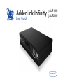
AdderLink Infinity {
User Guide
ALIF1000
ALIF2000
Front panel indicators................................................................22
Further information
Getting assistance.......................................................................23
Appendix.....................................................................................24
RS232 ‘null-modem’ cable pin-out........................................24
Supported video modes........................................................24
ALIF 1000 general specifications...........................................24
ALIF 2000 general specifications...........................................24
Warranty.....................................................................................25
Safety information.....................................................................25
Radio Frequency Energy............................................................26
Index
Mounting......................................................................................8
Connections..................................................................................9
TX video link..........................................................................10
TX audio links.........................................................................11
TX USB link.............................................................................12
TX AUX port...........................................................................12
TX power in............................................................................13
Power adapter identification...........................................13
TX/RX network link................................................................14
RX video display.....................................................................15
RX microphone & speakers...................................................16
RX USB devices.......................................................................17
RX AUX port...........................................................................17
RX power in............................................................................18
Power adapter identification...........................................18
Operation
Installation
Initial configuration...................................................................19
Manual factory reset.............................................................19
Infinity browser-based configuration utility........................20
Performing an upgrade.............................................................21
AdderLink ALIF1000T and ALIF1000R unit features...................3
AdderLink ALIF2000T and ALIF2000R unit features...................4
What’s in the box (ALIF1000).......................................................5
What’s in the box (ALIF2000).......................................................6
What you may additionally need................................................7
Configuration
Introduction
Contents
1
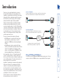
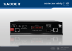
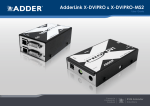
One-to-many configuration
Using multicast techniques, an unlimited number of receivers*
can receive video and audio data streams from a single TX unit.
ALIF RX
Gigabit
Ethernet
ALIF RX
* A maximum of twelve concurrent USB inputs (via
multiple RX units) are permitted to a single TX unit.
ALIF RX
ALIF TX
Mixing ALIF1000 and ALIF2000 units
It is possible to mix ALIF1000 and ALIF2000 transmitters and receivers. The only
exception is that the ALIF1000 units do not support dual link DVI video signals.
ALIF RX
ALIF TX
One-to-one configuration
The simplest configuration links one RX unit to a single TX unit, either by a direct
link or over much greater distances via a Gigabit (or Fibre) Ethernet network.
Thank you for choosing AdderLink Infinity, otherwise
known as ALIF. ALIF represents a major advance in the
capabilities of digital extenders and switches. By encoding
high quality DVI video, digital audio and USB connections
into Internet Protocol (IP) messages, ALIF offers highly
advanced and flexible signal switching capabilities.
Adder’s extensive knowledge of interfacing techniques
and high speed networking has allowed us to develop
new ways to break the chains of local DVI, USB and audio
connections. With ALIF, distance is finally no barrier to high
specification, high performance computing. Furthermore,
since all signals are now IP, the most elaborate and yet
simple-to-use switching and multicast techniques make
possible a great variety of uses.
There are two main models within the ALIF family:
• ALIF1000 supports one single link DVI video stream,
plus microphone, speakers and up to four USB
peripherals. ALIF1000 units are linked using Gigabit
Ethernet.
• ALIF2000 supports either two single link DVI video
streams or one dual link (very high resolution) DVI video
stream. This is in addition to microphone, speakers
and up to four USB peripherals. ALIF2000 units can be
linked using Gigabit Ethernet or Fibre Optic Links.
In both model types, there is a TX transmitter and an RX
receiver. The former attaches to a single computer; the
latter to your DVI video monitor, microphone, speakers and
up to four USB peripherals. The distance between them is
limited only by the size of your network.
In addition to separating one computer and its peripherals,
ALIF promotes sharing. You can arrange for a limitless
number of screens and speakers, distributed anywhere
across the network, to receive video and audio. You can
also switch between any number of transmitter units from
a single screen, keyboard and mouse in order to monitor a
potentially vast collection of remote systems.
All units feature browser-based configuration utilities to
allow quick and easy set up, from near or far.
Introduction
2
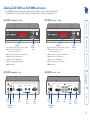
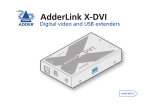
AdderLink ALIF1000T and ALIF1000R unit features
The ALIF1000 units are housed within durable, metallic enclosures with most connectors situated at the rear panel only the Ethernet ports are situated at the front panel. The smart front faces feature the operation indicators.
ALIF1000R (receiver) - front
TRANSMIT
RECEIVER
AdderLink
AdderLink
www.adder.com
www.adder.com
NET SER AUD USB DVI PWR
• NET On when valid network link is present.
Flashes when the unit is in error.
Gigabit
Ethernet
port
Indicators
These six indicators clearly show the key aspects of operation:
• NET On when valid network link is present.
Flashes when the unit is in error.
• SER On when the AUX (serial) port is enabled and active.
• AUD On when audio is enabled and active.
• AUD On when audio is enabled and active.
• USB On when USB is enabled and active.
• USB On when USB is enabled and active.
• DVI On when DVI video is enabled and active.
• DVI On when DVI video is enabled and active.
• PWR Power indicator.
• PWR Power indicator.
INDOOR
USE ONLY OPTIONS
DVI-D
ALIF1000R (receiver) - rear
LINE OUT
LINE IN
AUX
INDOOR
USE ONLY
OPTIONS
1 2
ON
1 2
COMPUTER
USB
port
Configuration
switches
Video
input
Audio
line
in/out
5V
AUX
(serial)
port
2.5A
1 2
Power
input
USER CONSOLE
Video
output
USB
ports
Audio
line
in/out
AUX
(serial)
port
Power
input
AUX
1 2
ON
2.5A
LINE IN/
LINE OUT
MIC IN
DVI-D
ALIF1000T (transmitter) - rear
• SER On when the AUX (serial) port is enabled and active.
Gigabit
Ethernet
port
NET SER AUD USB DVI PWR
Indicators
These six indicators clearly show the key aspects of operation:
5V
ALIF1000T (transmitter) - front
Configuration
switches
3
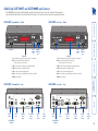
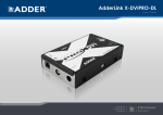
AdderLink ALIF2000T and ALIF2000R unit features
The ALIF2000 units are housed within durable, metallic enclosures with most connectors situated at the rear panel only the Ethernet and fibre ports are situated at the front panel. The smart front faces feature the operation indicators.
TRANSMIT
NET SER AUD USB
DVI PWR
NET SER AUD USB
Reserved
Fibre
module
slot
DVI PWR
Reserved
Gigabit
Ethernet
port
Indicators
These six indicators clearly show the key aspects of operation:
Fibre
module
slot
Gigabit
Ethernet
port
Indicators
These six indicators clearly show the key aspects of operation:
• NET On when valid network link is present.
Flashes when the unit is in error.
• SER On when the AUX (serial) port is enabled and active.
• SER On when the AUX (serial) port is enabled and active.
• AUD On when audio is enabled and active.
• AUD On when audio is enabled and active.
• USB On when USB is enabled and active.
• USB On when USB is enabled and active.
• DVI On when either or both DVI Video channels are enabled.
• DVI On when either or both DVI Video channels are enabled.
• PWR Power indicator.
• PWR Power indicator.
ALIF2000R (receiver) - rear
DVI-D-2
DVI-D-2
AUX
DVI-D-1
DVI-D-1
OPTIONS
• NET On when valid network link is present.
Flashes when the unit is in error.
ALIF2000T (transmitter) - rear
INDOOR
USE ONLY
RECEIVER
www.adder.com
AdderLink
www.adder.com
AdderLink
ALIF2000R (receiver) - front
ALIF2000T (transmitter) - front
1 2
ON
5V
2.5A
IN
1 2
Power
input
Configuration
switches
OUT
COMPUTER
USB
port
Primary
video
input
Secondary
video
input
5V
Audio
line
in/out
AUX
(serial)
port
4A
Power
input
Configuration
switches
USB
ports
Secondary
video
output
Primary
video
output
Audio
line
in/out
AUX
(serial)
port
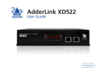
4
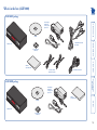
What’s in the box (ALIF1000)
ALIF1000T package
CD-ROM
NET
SE
R AU
D
USB
DV
I PW
R
TR
AN
SM
IT
ALIF1000T unit
Combined DVI-D and USB
cable (1.8m)
ww
w.ad
de
r.com
Four self-adhesive
rubber feet
ALIF1000
Quick Start Guide
Serial null modem cable 2m
2 x Audio cable 2m
(3.5mm stereo jacks)
Lin
k
Ad
der
Power adapter
(12.5W) and
country-specific
power lead
ALIF1000R package
Power adapter
(12.5W) and
country-specific
power lead
Ad
der
Lin
k
CD-ROM
NET
ALIF1000R unit
SE
R AU
D
USB
DV
I PW
R
RE
CE
IV
ER
ALIF1000
Quick Start Guide
ww
w.ad
de
r.com
Four self-adhesive
rubber feet
5
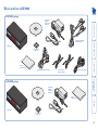
What’s in the box (ALIF2000)
ALIF2000T package
CD-ROM
NET
SE
R AU
D
USB
DV
I PW
R
TR
AN
SM
Combined dual link DVI-D
and USB cable (1.8m)
IT
ww
w.ad
de
r.com
ALIF2000T unit
Four self-adhesive
rubber feet
ALIF2000
Quick Start Guide
Serial null modem cable 2m
2 x Audio cable 2m
(3.5mm stereo jacks)
Single link DVI-D to DVI-D video cable
Lin
k
Ad
der
Power adapter
(20W) and
country-specific
power lead
ALIF2000R package
Power adapter
(20W) and
country-specific
power lead
Ad
der
Lin
k
CD-ROM
NET
SE
R AU
D
USB
DV
I PW
R
RE
CE
IV
ER
ALIF2000
Quick Start Guide
ww
w.ad
de
r.com
ALIF2000R unit
Four self-adhesive
rubber feet
6
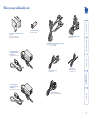
Fibre module (for ALIF2000)
Part number: SFP-MM-LC
Single link DVI-D to DVI-D video cable
Part number: VSCD1
Combined dual link DVI-D and USB (USB type A to B) cable
Part numbers:VSCD3 (1.8m length)
VSCD4 (5m length)
Power adapter (12.5W) and
country-specific power lead
for ALIF1000 units
Part number: PSU-IEC-5VDC-2.5A
Two 19” rack-mount brackets and four screws
Part numbers:
One unit per 1U rack slot: RMK4S
Two units per 1U rack slot: RMK4D
What you may additionally need
Audio cable 2m
(3.5mm stereo jacks)
Part number: VSC22
Power adapter (20W) and
country-specific power lead
for ALIF2000 units
Part number: PSU-IEC-5VDC-4AMP
Serial null modem cable 2m
Part number: CAB-9F/9F-NULL-MODEM
USB cable 2m (type A to B)
Part number: VSC24
7
Installation
Mounting
Connections
Rack brackets
The optional brackets (plus four screws), allow the
units to be secured within a standard rack slot.
Note: The ALIF units and their power
supplies generate heat when in operation
and will become warm to the touch.
Do not enclose them or place them in
locations where air cannot circulate to
cool the equipment. Do not operate
the equipment in ambient temperatures
exceeding 40oC. Do not place the
products in contact with equipment
whose surface temperature exceeds 40oC.
There are two main mounting methods for transmitter and receiver units:
• The supplied four self-adhesive rubber feet
• Optional rack brackets
TIO
1
5V
NS
LIN
E
MI IN/
CI
N LI
NDEV
IO
-DU
T
2
2.5
SAE 1 2
RC
ON
OP
SO
LE
AU
X
US
ER
LIN
E
MI IN/
CI
N LI
N
EO
CO
IN
US DOO
EO R
NL
Y
8
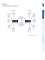
Connections
CABLE LINK
page 14
SERIAL
LINK
page 12
ALIF TX
OR
ALIF RX
FIBRE LINK
(ALIF2000 only)
page 14
POWER
IN
page 13
POWER
IN
page 18
USB
DEVICES
page 17
SERIAL
LINK
page 17
Click a connection to see details
USB
LINK
page 12
MIC &
SPEAKERS
page 16
VIDEO
LINK
page 15
AUDIO
LINKS
page 11
VIDEO
LINK
page 10
Installation involves linking the ALIF TX unit to various ports on the host
computer, while the ALIF RX unit is attached to your peripherals:
9
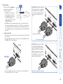
To make a video link
1 Wherever possible, ensure that power is disconnected from the ALIF and the
host computer.
2 Connect a digital video link cable to the DVI-D socket (ALIF1000) or DVI-D-1
(ALIF2000) on the TX unit rear panel:
[ALIF1000]
DV
I-
D
DVI-D link from
host computer
DV
I-
D-1
DV
I-
D-2
CO
MP
UT
ER
To primary video output port
To secondary video output port
[ALIF2000 when using one very high
resolution DVI-D dual link display]
Use a DVI-D Dual Link cable (such as
Adder part: VSCD3) to connect the
primary video port of the computer
system to the DVI-D-1 connector of
the ALIF2000. A dual link cable must
also be used at the RX unit.
DV
I-
D-1
DV
I-
D-2
MP
CO
MP
UT
ER
CO
[ALIF2000 when using two single link
DVI-D displays] Connect an additional
video input from the secondary video
port of the computer system using
the supplied secondary DVI-D link
cable.
AUDIO
ALIF units support DVI digital video
LINKS
signals and so use DVI-D video
connectors throughout.
USB
LINK
ALIF TX
LINK
• ALIF1000 models can support
a single high resolution DVI-D
SERIAL
ALIF RX
video display at pixel clocks up
LINK
POWER
to 165MHz (equating to an
IN
example display mode of 1920 x
1200 at 60Hz refresh).
• ALIF2000 models can simultaneously support up to two Single Link high
resolution video displays at pixel clocks up to 165MHz; or can alternatively
support a single Dual Link very high Resolution video display at pixel clocks
up to 330MHz (equating to an example display mode of 2560 x 1600 at 60
Hz refresh).
VIDEO
LINK
TX video link
3 Connect the plug at the other end of the cable to the corresponding DVI-D
video output socket of the host computer.
VSCD3 cable to primary video output port
10
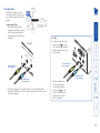
TX audio links
VIDEO
LINK
The ALIF units support two way
stereo digital sound so that you can
use a remote microphone as well as
speakers.
AUDIO
LINKS
LINK
ALIF RX
POWER
IN
[ALIF1000]
LIN
1 Connect an audio link cable
between the IN
socket on
the TX unit rear panel and the
speaker output socket of the
host computer.
DV
I-
D-1
EO
UT
AU
X
LIN
CO
Speaker link from
host computer
EI
MP
UT
[ALIF2000]
N
ER
Microphone link
to host computer
2 [Where a microphone is to be used]: Connect a second audio link cable
between the LINE IN socket on the TX unit rear panel and the Line In socket
of the host computer.
IN
Speaker link from
host computer
OU
T
SERIAL
LINK
Microphone link
to host computer
2 [Where a microphone is
to be used]: Connect a
second audio link cable
between the OUT socket
on the TX unit rear panel
and the Line In socket of
the host computer.
To make audio links
1 Connect an audio link cable
between the LINE OUT socket on
the TX unit rear panel and the
speaker output socket of the host
computer.
ALIF TX
USB
LINK
11
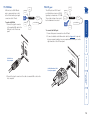
USB
LINK
To make a USB link
1 Connect the type B connector
of the supplied USB cable to the
USB port on the TX unit rear
panel.
SERIAL
LINK
ALIF TX
LINK
ALIF RX
TIO
NS
1
AUDIO
LINKS
USB
LINK
SERIAL
LINK
POWER
IN
OP
1
The AUX port is an RS232 serial
port that allows extension of RS232
signals up to a baud rate of 115200.
The port has software flow control,
but no hardware flow control.
ALIF TX
LINK
ALIF RX
POWER
IN
To connect the AUX port
1 Ensure that power is removed from the ALIF unit.
2 Connect a suitable serial ‘null-modem’ cable (see Appendix for pin-out)
between a vacant serial port on your computer and the AUX port on the
right hand side of the ALIF rear panel.
2
2
USB link from
host computer
AU
X
AUDIO
LINKS
VIDEO
LINK
ALIF units act as USB 2.0 hubs
and so can provide four sockets
at the RX unit with only a single
connection at the TX unit.
TX AUX port
VIDEO
LINK
TX USB link
2 Connect the type A connector of the cable to a vacant USB socket on the
host computer.
Serial (null-modem) link
from your computer
12
LINK
ALIF RX
POWER
IN
To apply power in
1 Attach the output lead from the power adapter to the 5V socket on the rear
panel of the unit.
2 Connect the IEC connector of the supplied country-specific power lead to
the socket of the power adapter.
IN
US DOO
EO R
NL
Y
1
2.5
A
Due to the increased power requirements of the ALIF2000 series, these models
are supplied with larger capacity (20W) power adapters. The standard 12.5W
and higher power 20W adapters use identical housings, so within installations
where both types are used, you need to double check the underside labels to
differentiate the two types:
12.5W model
(for ALIF1000)
20W model
(for ALIF2000)
Model: SA06-xxxxx-V
Input: 100-240V
Output: 5V 2.5A (12.5W Max.)
Model: SA06-xxxxx-V
Input: 100-240V
Output: 5V 4A (20W Max.)
x.)
OP
T
5V
Power adapter identification
SERIAL
LINK
ALIF TX
USB
LINK
1
Power lead from
power adapter
Note: Ensure that
Option switches
1 and 2 are both
in the ‘off’ (up)
position to enable
normal operation
of the unit.
3 Connect the power lead to a nearby main supply socket.
Note: Both the unit and its power supply generate heat when in operation and
will become warm to the touch. Do not enclose them or place them in locations
where air cannot circulate to cool the equipment. Do not operate the equipment
in ambient temperatures exceeding 40oC. Do not place the products in contact
with equipment whose surface temperature exceeds 40oC.
Ma
x-V
.5W
xxx
(12
6-x V
SA0 -240 2.5A
del: t: 100 5V
o
M pu ut:
In utp
O
Power adapter
No damage will be caused if the 12.5W adapter and the 20W adapter are used
in place of each other on either of the ALIF1000 or ALIF2000 units. However,
correct operation of ALIF2000 units can only be guaranteed if a 20W power
adapter is used. Always ensure that only ADDER 5-volt power supplies are used
to power the units.
AUDIO
LINKS
Each ALIF unit is supplied with an
appropriate power adapter. When
all other connections have been
made, connect and switch on the
power adapter unit.
Note: Please see Power adapter
identification shown opposite.
VIDEO
LINK
TX power in
13
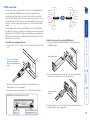
To link ALIF units using Gigabit Ethernet
1 Connect a CAT 5, 5e, 6, or 7 cable to the socket on the front panel of the ALIF
unit.
USB
LINK
SERIAL
LINK
ALIF TX
POWER
IN
LINK
LINK
ALIF RX
POWER
IN
MIC &
SPEAKERS
USB
DEVICES
SERIAL
LINK
To link ALIF units using fibre optic links (ALIF2000 only)
1 Insert the optional fibre module (SFP-MM-LC) into the aperture on the
ALIF2000 front panel:
Optional fibre module
CAT 5, 5e, 6, or 7 link either
directly from the other ALIF
unit or from a Gigabit Ethernet
switch
ww
w.a
d
AUDIO
LINKS
VIDEO
DISPLAY
ALIF units can be either connected directly to each other or via a Gigabit Ethernet
network. Additionally, ALIF2000 units can be networked by fibre optic links.
For direct links over Ethernet cable, the length of cable should not exceed 100
metres (328 feet). Network cables used for connections may be category 5, 5e, 6 or
7 twisted-pair cable. ALIF TX units have an autosensing capability on their network
interfaces, so for direct point-to-point connections, no ‘crossover’ Ethernet cable is
required.
For direct links over fibre optic links, either 50/125µm or 62.5/125µm MMF cables
with duplex LC connectors are suitable for use with the recommended fibre module
(Adder part number: SFP-MM-LC). Distances up to 500 metres are achievable with
50/125µm fibre and distances up to 300 metres with 62.5/125µm fibres. The fibre
cable must be a crossover cable.
VIDEO
LINK
TX/RX network link
der
.co
2 Connect the other end of the cable either to the other ALIF unit or to a
Gigabit Ethernet switch, as appropriate.
3 [For connections via a network] repeat steps 1 and 2 for the other ALIF unit. Transmit and receive
fibre links
[ALIF2000] When making Gigabit Ethernet links
AdderLink
www.adder.com
NET SER AUD USB
Reserved for
future use
2 Connect the transmit and receive fibre links to the fibre module and close
the latch over the link connectors to lock them into place.
m
DVI PWR
Use only the right hand port
for Gigabit Ethernet links
3 Connect the other end of the fibre links either to the other Infinity unit or to
a Gigabit Ethernet switch, as appropriate.
14
RX video display
[ALIF2000 when using two single link
DVI-D displays] Connect an additional
video input from the secondary video
port of the computer system using
the supplied secondary DVI-D link
cable.
DV
I-
D-2
DV
I-
D-1
US
ER
CO
NS
OL
MIC &
ALIF units support DVI digital
ALIF TX
SPEAKERS
video signals and so use DVI-D
video connectors throughout.
USB
LINK
ALIF RX
DEVICES
• ALIF1000 models can support
a single high resolution DVI-D
SERIAL
video display at pixel clocks up
LINK
POWER
to 165MHz (equating to an
IN
example display mode of 1920 x 1200 at 60Hz refresh).
• ALIF2000 models can simultaneously support up to two high resolution
video displays at pixel clocks up to 165MHz; or can alternatively support one
very high resolution video display (at pixel clocks up to 330MHz).
VIDEO
DISPLAY
E
To connect a digital DVI video display
1 Connect the lead from the video display to the DVI-D socket on the rear
panel of the ALIF unit.
To secondary video display
[ALIF1000]
To primary video display
DV
I-
DV
I-
D-2
DV
I-
D-1
US
ER
CO
NS
OL
E
To video display
[ALIF2000 when using one very high
resolution DVI-D dual link display]
Use a DVI-D Dual Link cable (such
as Adder part: VSCD3) to connect
the video display to the DVI-D-1
connector of the ALIF2000 RX unit.
A dual link cable must also be used at
the TX unit.
When using dual link on DVI-D-1, the
DVI-D-2 port will be disabled.
If DVI-D-2 is already being used, then
it must be disconnected before dual
link operation can occur on DVI-D-1.
D
VSCD3 cable to primary
video display
15
ALIF RX
POWER
IN
USB
DEVICES
LINK
LINK
MIC &
SPEAKERS
SERIAL
LINK
To connect a microphone (or line in) and/or speakers
1 Connect the lead from a mono microphone or, alternatively, a line in
connection from an audio device to the 3.5mm socket labelled LINE IN/MIC IN
on the rear panel.
2 Connect the lead from stereo speakers or, alternatively, a line out
connection from an audio device to the 3.5mm socket labelled LINE OUT on
the rear panel.
[ALIF2000]
1 Connect the lead from a mono
microphone to the 3.5mm socket
labelled
on the rear panel.
1
AU
X
[ALIF1000]
LIN
E
MI IN/
CI
N LI
NE
Connection from
microphone or line in
from audio device
CO
NS
OL
Link in from
microphone
OU
T
Link out to
speakers
E
Connection from
speakers or line out to
audio device
3 Once the unit has been fully connected and powered on, access the RX
System Configuration page to check that the Audio Input Type setting
matches the connection that you have made to the port: line, mic or mic
boost (the latter provides +20dB gain).
2 Connect the lead from stereo speakers to
the 3.5mm socket labelled
on the rear
panel.
3 Once the unit has been fully connected
and powered on, access the RX System
Configuration page to check that the
Audio Input Type setting matches the
connection that you have made to the
port: mic or mic boost (the latter provides
+20dB gain).
ALIF TX
The ALIF unit can support a
microphone as well as speakers
providing the necessary
connections have been made
between the ALIF TX unit and the
host computer.
VIDEO
DISPLAY
RX microphone & speakers
16
LINK
POWER
IN
To connect the AUX port
1 Ensure that power is removed from the ALIF unit. 2 Connect a suitable serial ‘null-modem’ cable (see Appendix for pin-out)
between the AUX port on the right hand side of the ALIF rear panel and
your remote serial device.
LIN
EO
UT
AU
X
LIN
E
MI I
CI
ER
CO
NS
OL
Serial (null-modem) link
from your computer
E
Connection from USB device
Supported USB Devices
USB devices are supported using True Emulation technology. This means that
the signals of each USB peripheral are emulated to the computer so that full
functionality is available, subject to the following limitations:
• Keyboards, mice and other HID devices are supported.
• Storage devices (i.e. flash drives, USB hard disks, CD-ROM drives) are
supported, but they may operate more slowly than with a direct connection.
• Isochronous devices (including microphones, speakers, webcams and TV
receivers) are not currently supported.
• Many other devices (such as printers, scanners, serial adapters and specialist
USB devices) will work, but due to the huge variety of devices available,
successful operation cannot be guaranteed.
USB
DEVICES
SERIAL
LINK
/
US
ALIF RX
MIC &
SPEAKERS
ALIF TX
To connect a USB device
1 Connect the lead from the device to
any of the four USB sockets on the rear
panel of the ALIF unit.
The AUX port is an RS232 serial
port that allows extension of
RS232 signals up to a baud rate
of 115200. The port has software
flow control, but no hardware
flow control.
MIC &
The ALIF RX unit has four USB
ALIF TX
SPEAKERS
ports to which peripherals may
be connected. The ports are
USB
LINK
LINK
ALIF RX
DEVICES
interchangeable. To connect
more than four peripherals, one
SERIAL
or more USB hubs may be used.
LINK
The total current that may be
POWER
IN
drawn from the USB ports is
1.2A, which should be sufficient
for a keyboard, mouse (no more than 100mA each) and any two other devices
(500mA maximum each). If more power for USB devices is required, use a
powered USB hub.
VIDEO
DISPLAY
RX AUX port
VIDEO
DISPLAY
RX USB devices
17
ALIF RX
LINK
POWER
IN
MIC &
SPEAKERS
USB
DEVICES
SERIAL
LINK
To apply power in
1 Attach the output lead from the power adapter to the 5V socket on the rear
panel of the unit.
2 Connect the IEC connector of the supplied country-specific power lead to
the socket of the power adapter.
A
20W model
(for ALIF2000)
Model: SA06-xxxxx-V
Input: 100-240V
Output: 5V 2.5A (12.5W Max.)
Model: SA06-xxxxx-V
Input: 100-240V
Output: 5V 4A (20W Max.)
1
Power lead from
power adapter
Note: Ensure that
Option switches
1 and 2 are both
in the ‘off’ (up)
position to enable
normal operation
of the unit.
3 Connect the power lead to a nearby main supply socket.
Note: Both the unit and its power supply generate heat when in operation and
will become warm to the touch. Do not enclose them or place them in locations
where air cannot circulate to cool the equipment. Do not operate the equipment
in ambient temperatures exceeding 40oC. Do not place the products in contact
with equipment whose surface temperature exceeds 40oC.
M
x-V
.5W
xxx
(12
6-x V
SA0 -240 2.5A
del: 00
Mo put: 1 ut: 5V
In utp
O
Power adapter
No damage will be caused if the 12.5W adapter and the 20W adapter are used
in place of each other on either of the ALIF1000 or ALIF2000 units. However,
correct operation of ALIF2000 units can only be guaranteed if a 20W power
adapter is used. Always ensure that only ADDER 5-volt power supplies are used
to power the units.
1
2.5
12.5W model
(for ALIF1000)
ax.)
OP
T
5V
Due to the increased power requirements of the ALIF2000 series, these models
are supplied with larger capacity (20W) power adapters. The standard 12.5W
and higher power 20W adapters use identical housings, so within installations
where both types are used, you need to double check the underside labels to
differentiate the two types:
IN
US DOO
EO R
NL
Y
Power adapter identification
ALIF TX
Each ALIF unit is supplied with an
appropriate power adapter. When
all other connections have been
made, connect and switch on the
power adapter unit.
Note: Please see Power adapter
identification shown opposite.
VIDEO
DISPLAY
RX power in
18
Configuration
To perform a manual factory reset
1 Remove power from the ALIF unit.
2 Use a narrow implement (e.g. a straightened-out paper clip) press and
hold the recessed reset button on the front panel. Power on the unit and
then release the reset switch.
Ad
der
Lin
k
Configuring network switches to ensure efficient operation
With IP Multicast there is a risk that network segments can get saturated
with data that are not destined for any device on that segment. Unless some
intelligence is applied, it’s possible for a naive IP switch to pass multicast data
onto every port on the switch. This can lead to performance degradation and
wasted network bandwidth. Fortunately, however, modern switches employ a
technique known as IGMP Snooping (Internet Group Management Protocol)
which enables them to be selective about where they route multicast IP traffic
- routing it only through switch ports which contain devices that are specifically
interested in such traffic.
IGMP Snooping can significantly reduce the amount of traffic generated by
ALIF TX units that are configured for multicast operation. It is beyond the scope
of this document to detail how to enable and configure IGMP snooping for
particular Gigabit IP Switches. However, we strongly recommend that when
deploying an ALIF Network you should select IP switches that support IGMP
snooping, and this snooping should be enabled and appropriately configured.
ww
w.a
d
de
[ALIF1000]
A factory reset returns an ALIF TX or RX unit to its default configuration. You
can perform factory resets using either of the two configuration utilities or by
using this direct manual method.
Manual factory reset
r.co
m
[ALIF2000]
Use a straightened-out paper clip to press the reset button
while powering on the unit
After roughly eight seconds, when the factory reset has completed, five
of the front panel indicators will flash for a period of three seconds to
indicate a successful reset operation.
3 Remove and then re-apply power to start the unit in its default
configuration.
ALIF units are designed to be as flexible as possible, and this principle extends
also to their configuration.
• Where an ALIF TX and an ALIF RX are directly linked to each other, no
configuration action is required, provided that they have their factory default
settings in place. If the standard settings have been changed in a previous
installation, you merely need to perform a factory reset on each unit:
• Where ALIF units are connected via network links, you will need to specify
their network address details. This can be done using a computer system
temporarily linked to each ALIF unit via a network connection together with
the Infinity browser-based configuration utility. This configuration utility
also allows numerous other settings to be altered.
Initial configuration
19
ww
w.a
d
[ALIF2000] Note: Use the
right hand Ethernet port.
der
.co
m
2 Connect the other end of the link cable to your network.
3 Similarly, link your computer to the same network. Note: A Gigabit
connection is not essential for configuration purposes.
4 If not already switched on, power up your computer and the ALIF unit. You
are now ready to use the browser-based configuration utility.
Link from Ethernet
switch
To connect a computer system for browser-based configuration
1 Connect a suitable network cable to the Ethernet port on the front panel of
the ALIF unit.
To access the browser-based configuration utility
1 Temporarily connect the ALIF unit and a computer via a network, as
discussed opposite.
2 Run a web browser on your computer and enter the IP address of the ALIF
unit, e.g. http://169.254.1.33
The default settings are as follows:
• TX units - IP address: 169.254.1.33
• RX units - IP address: 169.254.1.32
Where the address of a unit is not known perform a manual factory reset
to restore the default address.
The opening page of the ALIF configuration utility will be displayed and you
can now use on-screen help for details of the functions that you wish to
perform.
The browser-based configuration utility within all TX and RX units requires
a network connection between the ALIF unit and a computer on the same
network. The configuration utility allows you to perform all of the following
functions:
• View/edit the IP network address and netmask,
• Configure separate IP network addresses for video, audio and USB,
• Configure multicast settings (on RX units),
• Configure video bandwidth settings (on TX units),
• View the current video output (on TX units),
• Perform a firmware upgrade,
• Perform a factory reset.
Infinity browser-based configuration utility
20
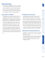
Finding the latest upgrade files
Firmware files for the ALIF units are available from the Technical Support
> Updates section of the Adder Technology website (www.adder.com).
To upgrade a single unit via network link
1 Download the latest upgrade file from the Adder Technology website.
Note: There are separate upgrade files for TX and RX units.
2 Temporarily connect the ALIF unit and a computer via a network (see
Infinity browser-based configuration utility section for details). 3 Run a web browser on your computer and enter the IP address of the ALIF
unit to be upgraded.
4 Click the Firmware Upgrade link. Within the Firmware Upgrade page, click
the Choose File button. In the subsequent file dialog, locate the downloaded
upgrade file - check that the file is correct for the unit being upgraded.
5 Click the Upgrade Now button. A progress bar will be displayed (however,
if your screen is connected to the unit being upgraded then video may
be interrupted) and the indicators on the front panel will flash while the
upgrade is in progress.
6 The indicators should stop flashing in less than one minute, after which the
unit will automatically reboot itself. The upgrade process is complete.
ALIF units are flash upgradeable using the method outlined here. However, for
larger installations we recommend that you use the AdderLink Infinity Manager
(A.I.M) to upgrade multiple ALIF units. When using the method below, the ALIF
unit will be upgraded in sequence.
Warning: During the upgrade process, ensure that power is not
interrupted as this may leave the unit in an inoperable state.
Performing an upgrade
21
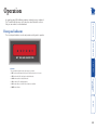
The six front panel indicators on each unit provide a useful guide to operation:
NET SER AUD USB DVI PWR
Indicators
These six indicators clearly show the key aspects of operation:
• NET On when valid network link is present. Flashes when the unit is in error.
Front panel indicators
In operation, many ALIF installations require no intervention once configured.
The TX and RX units take care of all connection control behind the scenes so
that you can continue to work unhindered.
Operation
• USB On when USB is enabled and active.
• DVI On when either or both DVI Video channels are enabled.
• PWR Power indicator.
• AUD On when audio is enabled and active.
• SER On when the AUX (serial) port is enabled and active.
22
Further information
in the UK:
in the US:
01954 780081
+1 888 275 1117
• Phone
in the UK:
in the US:
01954 780044
+1 888 932 3337
• Fax
• Email – [email protected]
• Adder Technology website – www.adder.com
Check the Support section of our website for the latest solutions and driver
files.
Getting assistance
This chapter contains a variety of information, including the following:
• Getting assistance - see right
• Appendix - RS232 ‘null-modem’ cable,
Supported video modes,
General specifications.
• Safety information
• Warranty
• Radio frequency energy statements
23
Appendix
RS232 ‘null-modem’ cable pin-out
RXD
TXD
3
3
TXD
DTR
4
4
DTR
DSR
6
6
DSR
DCD
1
1
DCD
GND
5
5
GND
RTS
7
7
RTS
CTS
8
8
CTS
Supported video modes
ALIF units support all VESA and CEA video modes.
ALIF 2000 general specifications
Casing (w x h x d): Construction: Weight: Mount kits: Power to adapter: Power to unit:
Operating temp: Approvals: 198mm (7.92”) x 44mm (1.76”) x 120mm (4.8”)
1U compact case, robust metal design
1.11kg (2.44lbs)
Rack mount - single or dual units per 1U slot.
VESA monitor / wall mount chassis.
100-240VAC 50/60Hz, 0.8A,
5VDC 20W
0ºC to 40ºC (32ºF to 104ºF)
CE, FCC
2
2
198mm (7.92”) x 44mm (1.76”) x 120mm (4.8”)
1U compact case, robust metal design
0.75kg (1.65lbs)
Rack mount - single or dual units per 1U slot.
VESA monitor / wall mount chassis.
100-240VAC 50/60Hz, 0.5A,
5VDC 12.5W
0ºC to 40ºC (32ºF to 104ºF)
CE, FCC
RXD
Casing (w x h x d): Construction: Weight: Mount kits: Power to adapter: Power to unit:
Operating temp: Approvals:
9pin D-type
female
9pin D-type
female
ALIF 1000 general specifications
24
•
•
•
•
For use in dry, oil free indoor environments only.
Warning - live parts contained within power adapter.
No user serviceable parts within power adapter - do not dismantle.
Plug the power adapter into a socket outlet close to the module that it is
powering.
Replace the power adapter with a manufacturer approved type only.
Do not use the power adapter if the power adapter case becomes damaged,
cracked or broken or if you suspect that it is not operating properly.
If you use a power extension cord with the units, make sure the total
ampere rating of the devices plugged into the extension cord does not
exceed the cord’s ampere rating. Also, make sure that the total ampere
rating of all the devices plugged into the wall outlet does not exceed the
wall outlet’s ampere rating.
Do not attempt to service the units yourself.
•
•
•
•
Adder Technology Ltd warrants that this product shall be free from defects in
workmanship and materials for a period of two years from the date of original
purchase. If the product should fail to operate correctly in normal use during the
warranty period, Adder will replace or repair it free of charge. No liability can be
accepted for damage due to misuse or circumstances outside Adder’s control.
Also Adder will not be responsible for any loss, damage or injury arising directly
or indirectly from the use of this product. Adder’s total liability under the terms
of this warranty shall in all circumstances be limited to the replacement value of
this product.
If any difficulty is experienced in the installation or use of this product that you
are unable to resolve, please contact your supplier.
Safety information
Warranty
25
Canadian Department of Communications RFI statement
This equipment does not exceed the class A limits for radio noise emissions from
digital apparatus set out in the radio interference regulations of the Canadian
Department of Communications.
Le présent appareil numérique n’émet pas de bruits radioélectriques dépassant
les limites applicables aux appareils numériques de la classe A prescrites dans
le règlement sur le brouillage radioélectriques publié par le ministère des
Communications du Canada.
This equipment generates, uses and can radiate radio frequency energy
and if not installed and used properly, that is, in strict accordance with the
manufacturer’s instructions, may cause interference to radio communication.
It has been tested and found to comply with the limits for a class A computing
device in accordance with the specifications in Subpart J of part 15 of FCC rules,
which are designed to provide reasonable protection against such interference
when the equipment is operated in a commercial environment. Operation of this
equipment in a residential area may cause interference, in which case the user at
his own expense will be required to take whatever measures may be necessary
to correct the interference. Changes or modifications not expressly approved by
the manufacturer could void the user’s authority to operate the equipment.
This equipment has been tested and found to comply with the limits for a class
A computing device in accordance with the specifications in the European
standard EN55022. These limits are designed to provide reasonable protection
against harmful interference. This equipment generates, uses and can radiate
radio frequency energy and if not installed and used in accordance with the
instructions may cause harmful interference to radio or television reception.
However, there is no guarantee that harmful interference will not occur in a
particular installation. If this equipment does cause interference to radio or
television reception, which can be determined by turning the equipment on
and off, the user is encouraged to correct the interference with one or more
of the following measures: (a) Reorient or relocate the receiving antenna. (b)
Increase the separation between the equipment and the receiver. (c) Connect
the equipment to an outlet on a circuit different from that to which the receiver
is connected. (d) Consult the supplier or an experienced radio/TV technician for
help.
FCC Compliance Statement (United States)
European EMC directive 2004/108/EC
A Category 5 (or better) twisted pair cable must be used to connect the units in
order to maintain compliance with radio frequency energy emission regulations
and ensure a suitably high level of immunity to electromagnetic disturbances.
All other interface cables used with this equipment must be shielded in order
to maintain compliance with radio frequency energy emission regulations and
ensure a suitably high level of immunity to electromagnetic disturbances.
Radio Frequency Energy
26
Adder Technology (Asia Pacific) Pty Ltd
8 Burn Road
#04-10, Trivex
369977
Singapore
Tel +65 6288 5767
Fax +65 9616 1283
Adder Corporation,
350R Merrimac Street,
Newburyport,
MA 01950,
United States of America
Tel: +1-888-932-3337
Fax: +1-888-275-1117
Adder Technology Limited,
Unit 5, Saxon Way,
Bar Hill, Cambridge,
CB23 8SL,
United Kingdom
Tel: +44 (0)1954 780044
Fax: +44 (0)1954 780081
© 2011 Adder Technology Limited
All trademarks are acknowledged.
Release 2.0d
December 2011
Part No. MAN-ALIF
Documentation by:
www.ctxd.com
27
R
Assistance 23
Dimensions 24
B
F
Bracket
rack mount 8
Brackets
fitting 8
Browser-based utility 20
Factory reset 19
Firmware
upgrade 21
Front panel 3
Front panel indicators 22
Rack mounting 8
Rear panel 3
Reset
manual 19
C
G
Safety information 25
Specifications 24
Switch
IGMP configuration 19
Cable spec
null modem 24
Configuration
browser-based utility 20
styles 2
Connections
network link 14
overview 9
RX audio 16
RX AUX port 17
RX power in 18
RX USB devices 17
RX video display 15
TX audio links 11
TX AUX port 12
TX power in 13
TX USB link 12
TX video link 10
Connectors
overview 3
Getting assistance 23
T
I
Troubleshooting 23
M
Manual factory reset 19
N
Null-modem cable
pin-out 24
P
U
Upgrade
firmware 21
V
Video modes 24
W
Warranty 25
Weight 24
IGMP 19
Indicators 3,22
Initial configuration 19
S
D
A
Index
Parts
optional 7
supplied 5,6
28