1
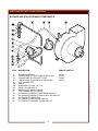
381
WELLS BLOOMFIELD, LLC
2 ERIK CIRCLE, P. O. Box 280 Verdi, NV 89439
telephone: 775-689-5703
fax: 775-689-5976
www.wellsbloomfield.com
SUPPLEMENTAL
SERVICE INSTRUCTIONS
for
VENTILATOR HOOD
SECTION
FRYER MODELS
WVAE_30F
WVPE-30F
WVAE-55F
WVAE-55FS
IMPORTANT: WELLS MANUFACTURING PROPRIETARY INFORMATION.
DISSEMINATION OF THIS INFORMATION TO ANYONE OTHER THAN
WELLS AUTHORIZED SERVICE AGENTS IS STRICTLY PROHIBITED.
TECHNICAL CONTENT OF THIS MANUAL IS DESIGNED FOR
USE BY QUALIFIED PROFESSIONAL TECHNICIANS ONLY.
PRINTED IN UNITED STATES OF AMERICA
p/n 502944 Rev. E ECN-13391
S381
071128
cps
PRECAUTIONS AND GENERAL INFORMATION
WARNING:
RISK OF INJURY
Installation procedures must
be performed by a qualified
technician with full
knowledge of all applicable
electrical and plumbing
codes. Failure can result in
personal injury and property
damage.
WARNING:
BURN HAZARD
POSSIBLE HOT OIL SPILL
AVOID CONTACT WITH HOT OIL
USE CARE WHEN HANDLING OIL TO
AVOID SPILLS
Discharge of the Ansul® fire suppression system may result in foaming
of the oil in the frypot. Serious burns and other injuries can result from
contact with hot oil and from slipping in spilled oil. Clean up oil spills
promptly.
SHOCK HAZARD
All servicing requiring
access to non-insulated
electrical components must
be performed by a qualified
technician.
DO NOT open any access
panel that requires the use
of tools unless you are
qualified to do so. Failure to
follow this warning can
result in severe electrical
shock.
CAUTION:
RISK OF
DAMAGE
This ventilator and attendant fryer are intended for use only in
commercial establishments, where all operators are familiar with
the appliance use, limitations and associated hazards. Operating
instructions and warnings must be read and understood by all
operators and users.
This ventilator hood system is designed to reduce odor emissions,
but will not completely eliminate cooking odors. Air exchange at the
installation site must comply with the requirements of the local
jurisdictional authority. To ensure that odors do not build-up,
recommended minimum air exchange is 400 cfm into and out of the
site.
Cleanliness of this appliance is essential to good sanitation. Read and
follow all included cleaning instructions and schedules to ensure the
safety of the food product.
Disconnect this appliance from electrical power before performing any
maintenance or servicing.
DO NOT splash or pour water on, in or over any controls, control
panel or wiring.
The technical content of this manual, including any wiring diagrams,
schematics, parts breakdown illustrations and/or adjustment
procedures, is intended for use by qualified technical personnel.
Any procedure which requires the use of tools must be performed by a
qualified technician.
This appliance is made in the USA. Unless otherwise noted, this
appliance has American sizes on all hardware.
xi
381 502944 Service Manual for NFPA Hood
DO NOT connect or
energize this appliance until
all installation
instructions are read and
followed. Damage to the
appliance will result if these
instructions are not followed.
This ventilator hood system is designed as part of a fryer intended to
prepare food for human consumption. No other use of this product is
authorized or recommended by the manufacturer or its agents.
TABLE OF CONTENTS
Precautions & General Information …………………………… xi
Features & Operating Controls …………………………………. 2
Hood Operation …………………………………………...……… 4
Troubleshooting Suggestions …………………………………… 6
Servicing Instructions
Fire Damper …………………………………………………… 7
Filter Interlock …………………………………………………. 8
Blower & Status Sensor System ……………………………. 10
Ansul® System ………………………………………………… 12
Exploded Views & Parts Lists ………………………………….. 14
Wiring Diagrams …………………………………………..……… 16
INTRODUCTION
This manual contains information needed to properly service and repair the hood portion of ventless floor
fryers.
This manual applies to the following Wells Manufacturing models:
WVAE-30F, WVPE-30F, WVAE-55F, WVAE-55FS
SPECIFICATIONS
381 502944 Service Manual for NFPA Hood
This hood system is common to several Wells Manufacturing products. For installation, operation and
maintenance instructions, electrical specifications and general dimensions, refer to the General Layout
Data, Installation Instructions and Operation Manual for the specific model.
1
FEATURES & OPERATING CONTROLS
VENTILATOR WARNINGLIGHT PANEL
SIDE VIEW
BACK VIEW
f.17 a.18 a.19
FRONT VIEW
f.20
v.6
v.7
v.2
v.8
v.3
v.4
v.5
f.21
f.22
v.9
f.23
v.25
f.24
a.10
a.15
a.15
a.11
v.12
f.1
a.13
a.14
FRYER
WVAE-30,
WVAE-55 or
WVPE-30
f.26
f.16
Note:
Items beginning with “a. ...” are part of the Ansul® fire suppression system
Items beginning “f. ...” are part of the FRYER
Items beginning “v. ...” are part of the VENTILATOR
FRYER position turns ON the VENTILATOR POWER LIGHT and
BLOWER. If, within 10 seconds, there is sufficient AIR FLOW for
proper operation, the POWER LIGHT will remain ON and the fryer will
operate.
If, after 10 seconds, there is not sufficient AIR FLOW for proper
operation, the BLOWER and VENTILATOR POWER LIGHT will turn
OFF and the SERVICE REQUIRED LIGHT will turn ON.
Note: The POWER SWITCH must be turned OFF to reset the system
before the fryer can be operated.
v.2 VENTILATOR POWER
LIGHT (green)
Glows when the FRYER POWER SWITCH is ON.
v.3 CHECK FILTERS
LIGHT (amber)
Glows when GREASE BAFFLE and/or HEPA AIR FILTER are not
properly installed. When ON, the fryer heating elements are de-activated.
Make sure both the HEPA FILTER and the GREASE BAFFLE fully
depresses their respective filter sensor tang (f.25, lower left corner of the
filter rail), which proves the filters are in the proper position. When the filters
are in the proper position, the CHECK FILTER light will not be lit.
2
381 502944 Service Manual for NFPA Hood
f.1 POWER SWITCH
(FRYER - OFF - FILTER)
FEATURES & OPERATING CONTROLS (continued)
v.4
REPLACE FILTERS
LIGHT (amber)
Will turn ON if either or both the HEPA AIR FILTER and/or CHARCOAL
FILTER are due for replacement. The fryer will continue to operate, but
the air filter(s) must be changed in a timely manner or it (they) will clog,
the SERVICE REQUIRED LIGHT will turn ON and the fryer will shutdown
until the filter(s) have been replaced.
v.5
SERVICE REQUIRED
LIGHT (red)
Will turn ON and the fryer will shut down whenever dirty filters cause
insufficient ventilator AIR FLOW for proper operation. Replace both the
HEPA FILTER and the CHARCOAL FILTER to resume operation.
v.6
EXHAUST COLLAR
Contains fire damper with pre-installed 285ºF (141ºC) fusible link.
v.7
VENTILATION BLOWER
Provides airflow.
v.8
UPPER REAR
REMOVABLE PANEL
Provides access to BLOWER and PRESSURE SWITCHES.
v.9
PRESSURE SWITCHES
Detect blower operation and filter status.
a.10 ANSUL® ACTUATOR
Controls the release of the fire suppression media
381 502944 Service Manual for NFPA Hood
a.11 ANSUL® SYSTEM
Provides pressurization of the fire suppression system
PRESSURE CARTRIDGE
v.12 LOWER REAR
REMOVABLE PANEL
Provides access to fire suppression system components.
a.13 FIRE SUPPRESSION
MEDIA TANK
1.5 gal. container of Ansulex® R-102 liquid fire suppression media.
a.14 FRYPOT FUSIBLE LINK
450ºF link protects against run-away heater.
a.15 MANUAL PULL STATION
Provides for manual activation of the fire suppression system
f. 16 REAR LEGS
REPLACE CASTERS WHEN A REMOTE MANUAL PULL STATION IS
INSTALLED.
v.17 VACUUM TAP
Senses low-pressure side of BLOWER.
a.18 FILTER CHAMBER
FUSIBLE LINK
280ºF fusible link provides protection against fire in the upper portion of
the hood.
a.19 DISCHARGE NOZZLES
Control dispersal of the fire suppression media.
v.20 TOP REMOVABLE PANEL Provides access to warning light panel wiring.
v.21 CHARCOAL FILTER
Provides for some odor control. Replace this filter each time the HEPA
FILTER is replaced.
v.22 HEPA FILTER
Traps most grease and other cooking vapor particles. Replace the HEPA
FILTER and the CHARCOAL FILTER at the same time.
v.23 GREASE BAFFLE
Separates grease and other liquids from the air stream.
v.24 GREASE CUP
Catches liquids trapped by the GREASE BAFFLE.
f.25 FILTER SENSORS
Detect GREASE BAFFLE and HEPA FILTER.
f.26 GREASE TRAY
Collects liquids that drain from the top of the fryer.
3
OPERATION
VENTILATOR
POWER ON
CHECK
FILTERS
REPLACE
FILTERS
SERVICE
REQUIRED
NOTE: Never press the POWER SWITCH to FRYER unless the HEATING ELEMENTS are
covered with either shortening (or, in the case of cleaning, water - NEVER MIX OIL AND WATER ).
Check the COLD OIL LINE for the proper shortening level.
NOTE: This fryer is designed to be used with LIQUID SHORTENING ONLY, unless it is
equipped with the solid shortening option (available only on model WVAE-55FS).
Lard and solid shortening will solidify in the filter pump, causing pump failure.
1. Verify that the CHARCOAL FILTER (if used), HEPA FILTER and GREASE BAFFLE are properly
installed in their respective locations. The HEPA FILTER and GREASE BAFFLE activate
MECHANICAL INTERLOCK SWITCHES when they are in their proper position. Activating both
mechanical interlock switches energizes the heating element.
The CHARCOAL FILTER does not activate a position sensor, thus the ventilator may be operated
without this optional filter.
A pressure tap on the blower housing and a vacuum tap downstream of the filters (but before the
blower) feed pneumatic signals to the AIRFLOW VACUUM SWITCH and to the SERVICE FILTER
VACUUM SWITCH.
2. Press the POWER SWITCH to the FRYER position:
The BLOWER will start and the VENTILATOR POWER ON (green light) will light.
b.
The TEN SECOND DELAY RELAY will be energized, bypassing the AIRFLOW VACUUM
SWITCH during the ten-second countdown.
3. If, after the ten second delay, sufficient air flow is sensed by the AIRFLOW VACUUM SWITCH , the
BLOWER will continue to run and the fryer will be energized.
4. If, after the ten second delay, sufficient air flow has not been sensed by the AIR FLOW VACUUM
SWITCH, the BLOWER will shut down and the SERVICE REQUIRED (red light) will be lit.
5. If either the HEPA FILTER or GREASE BAFFLE should be removed or become dislodged, the
respective MECHANICAL INTERLOCK SWITCH will open, the fryer will be de-energized and the
CHECK FILTERS (amber light) will light.
6. If either the HEPA FILTER or the CHARCOAL FILTER, or in combination, become partially clogged,
the SERVICE FILTER VACUUM SWITCH will close and the REPLACE FILTERS (amber light) will
light. The fryer will continue to operate. This is a WARNING that the filters are approaching the end
of their service life. The filter(s) must be replaced before they become so clogged that the fryer/
blower is shut down by the AIR FLOW VACUUM SWITCH.
4
381 502944 Service Manual for NFPA Hood
a.
OPERATION (continued)
IMPORTANT: When the REPLACE FILTERS (amber light) comes on, the fryer will soon shut
down. The actual time between the light coming on and the fryer shutting down depends upon the
type and quantity of product being cooked. The operator must prepare to change the filter(s) by
making sure that fresh replacement filters are on hand at the fryer location.
7. If either the HEPA FILTER or the CHARCOAL FILTER, or in combination, become clogged to the
point that sufficient airflow is not sensed by the AIRFLOW VACUUM SWITCH, the switch will open.
The BLOWER will shut down, the fryer will be de-energized and the SERVICE REQUIRED (red
light) will light.
The manufacturer recommends replacing both the HEPA FILTER and the CHARCOAL FILTER at
the same time. Verify that the air flow arrows point toward the fan.
After the filter(s) are replaced, the POWER SWITCH must be pressed to OFF, then back to FRYER
to reset.
8. Any loss of electrical power will disable the fryer. After power is restored, the POWER SWITCH
must be pressed to OFF, then back to FRYER to reset.
9. The fryer is de-energized anytime the Ansul® fire suppression system has discharged, or is
otherwise is not CHARGED and COCKED. The BLOWER will continue to run.
10. Both the fryer and the BLOWER are de-energized when the POWER SWITCH is in the FILTER
position.
11. Control power is routed through a jumper at the REMOTE INTERLOCK TERMINAL BLOCK.
For installations where remote shut-down is required, the jumper is removed and power is routed
through the remote interlock circuit.
Both the fryer and the BLOWER are de-energized when the remote interlock circuit is open.
381 502944 Service Manual for NFPA Hood
12. Some jurisdictions require that an alarm signal be generated should the fire suppression system be
activated. A set of dry contacts are provided at the BUILDING ALARM RELAY for this purpose.
IMPORTANT: DO NOT connect power to the building alarm relay.
5
TROUBLESHOOTING SUGGESTIONS
SYMPTOM
BLOWER/FRYER NOT OPERATING
VENTILATOR POWER (green light) not lit
BLOWER/FRYER NOT OPERATING
VENTILATOR POWER (green light) lit
BLOWER/FRYER NOT OPERATING
SERVICE REQUIRED (red light) lit
REPLACE FILTERS (amber light) lit
Blower/Fryer operating normally
CHECK FILTERS (amber light) lit
Blower operating normally
Fryer not operating
VENTILATOR POWER (green light) not lit
All other operations normal
SUGGESTED REMEDY
POWER SWITCH not in FRYER
Press POWER SWITCH to FRYER position
Fryer POWER SWITCH defective
Replace power switch
10-20 -second timer defective
Replace timer
Remote interlock circuit open
Locate and rectify open circuit condition
Blower wiring defective
Repair wiring
Blower fan jammed
Clean blower fan
Blower motor defective
Repair/replace motor
HEPA FILTER and/or CHARCOAL filters plugged
Replace both HEPA and CHARCOAL FILTER
AIRFLOW VACUUM switch not made
Locate and rectify reason SWITCH not
Vacuum tap on blower fan housing plugged
Clean vacuum tap
For continuing problems with plugged tap,
upgrade to new-style fan housing.
AIRFLOW vacuum switch defective
Replace vacuum switch
HEPA FILTER and/or CHARCOAL filters
becoming plugged
Replace both HEPA and CHARCOAL FILTER
Vacuum tap on blower fan housing restricted
Clean vacuum tap
For continuing problems with plugged tap,
upgrade to new-style fan housing.
SERVICE FILTERS vacuum switch defective
Replace vacuum switch
GREASE BAFFLE and/or HEPA FILTER out of
place
Install BAFFLE / HEPA FILTER properly.
Filter sensing switch defective or out of
Adjust or replace switch
Defective CONTROLLER or TEMP CONTROL
‘STAT
Repair or replace
HI-LIMIT ‘STAT tripped
Clean frypot & reset ’stat
HI-LIMIT ‘STAT defective
Replace hi-limit thermostat
Defective relay
Replace relay
Fryer with Solid State Controller - Programmed
temp too low
Program proper temperature
Fryer with Solid State Controller - STANDBY or
CLEANING mode selected
Select a menu key
Indicator light defective
Repair/replace light
6
381 502944 Service Manual for NFPA Hood
FRYER NOT OPERATING
Blower operating normally
Check Filters (amber light) not lit
POSSIBLE CAUSE
SERVICING INSTRUCTIONS
FIRE DAMPER COMPONENTS
ITEM
DESCRIPTION
5
9
DAMPER SUPPORT
FIRE DAMPER ASSEMBLY,
(fusible link rated at 285ºF/141ºC)
SERVICE PART
501187
FIRE DAMPER ASSEMBLY INSTRUCTIONS
1. The FIRE DAMPER is accessible by removing the UPPER REAR
cover. The FIRE DAMPER sets in the DAMPER SUPPORT and
may be removed by lifting straight out.
2. The FIRE DAMPER normally needs no maintenance. If it becomes
heavily covered in grease and/or dust it must be replaced.
381 502944 Service Manual for NFPA Hood
3. If the FIRE DAMPER malfunctions or if the fusible link releases,
the manufacturer recommends that the entire FIRE DAMPER
ASSEMBLY be replaced.
4. Reinstall the FIRE DAMPER with the “THIS SIDE UP FOR
HORIZONTAL MOUNTING” arrow pointing away from the
BLOWER, and the shutter assembly on the wide side of the
DAMPER SUPPORT (i.e. on the left as seen from the rear of the
hood).
7
SERVICING INSTRUCTIONS (continued)
FILTER INTERLOCK COMPONENTS
DESCRIPTION
SERVICE PART NO.
13
15
24
25
34
37
41
43
48
MAGNET ARM
INTERLOCK BLOCK
SHORT LINK
COVER, INTERLOCK ASSEMBLY
LONG LINK
PROXIMITY SWITCH
BUSHING
PAWL
MAGNET
AA
BB
CC
DD
EE
FF
GG
HH
JJ
“E” CLIP, .122ID SS
NUT 8-32 (pk100)
SET SCREW 8-32 x 3/4 ALLEN SOCKET
SCREW 8-32 x FLAT HEAD (pk 50)
SCREW 8-32 x 5/16
SCREW 4-40 x 3/8
WASHER #4
LOCK WASHER #4
NUT 4-40
501409
501448
63948
8
50136
50153
65193
7506-39
68748
8543-74
381 502944 Service Manual for NFPA Hood
ITEM
SERVICING INSTRUCTIONS (continued)
FILTER INTERLOCK ASSEMBLY INSTRUCTIONS
There are two FILTER INTERLOCK assemblies.
a. The GREASE BAFFLE interlock is on the left.
This assembly uses the LONG LINK so that the PAWL
fits into the front filter rail.
b. The HEPA FILTER interlock is on the right.
This assembly uses the SHORT LINK so that the PAWL
fits into the rear filter rail.
1. Install two SET SCREWS into the edge of each
INTERLOCK BLOCK.
2. With the INTERLOCK BLOCK laying flat, the set screws
pointing away from you, and the set screw that is closest
to the end in the upper right corner, insert a BUSHING in
the right hole, and insert a BUSHING in the left hole (for
the GREASE BAFFLE INTERLOCK), or in the middle
hole (for the HEPA FILTER INTERLOCK). (Fig. A)
3. Install a MAGNET in the MAGNET ARM. Align the
magnets so they repel each other when they are in
the normal operating position. (Fig. B)
4. Assemble the PAWL and the MAGNET ARM to the LINK.
The short leg of the “L” slot will point down. Slide the link
into the top slot of the small studs. Use the LONG LINK
for the GREASE BAFFLE INTERLOCK, and the SHORT
LINK for the HEPA FILTER INTERLOCK. (Fig. C)
381 502944 Service Manual for NFPA Hood
Slide the large studs into the BUSHINGS and secure
with “E” CLIPS. The pawl and arm should operate freely.
5. Push the SET SCREWS through the appropriate holes in
the filter rail and secure with nuts. The pawl and arm
should continue to operate freely.
6. Install the COVER and secure with two screws from the
filter rail side.
7. Install the PROXIMITY SWITCHES on the ledge in the
blower section. The switches must be installed with the
thickest edge against the wall. Before tightening the screws,
push the switches as far forward and as far apart as they will
go.
8. Check operation with an ohm meter on the leads of the
PROXIMITY SWITCHES while pressing and releasing
the PAWLS. With the pawl depressed, the reading
should be zero ohms.
9
SERVICING INSTRUCTIONS (continued)
BLOWER AND STATUS SENSOR COMPONENTS
ITEM
SERVICE PART NO.
BLOWER ASSEMBLY
501731
VACUUM SWITCH, SHUTDOWN (& RED LIGHT)
501379
VACUUM SWITCH, REPLACE FILTER
501380
TUBING, HOSE (LOW PRESS TO SWITCHES)
501516
“TEE” CONNECTOR
ELBOW
QUICK SEAL FITTING, 1/4” x 1/4”
3/8 MPT CLOSE NIPPLE
HOSE BARB (TUBING TO HOSE)
“TEE” CONNECTOR (HI PRESS)
S/S TUBING (HI PRESS TO SHUTDOWN SWITCH)
S/S TUBING (HI PRESS TO REPLACE FILTER SWITCH)
S/S TUBING (TO SWITCHES)
S/S TUBING (TO SHUTDOWN SWITCH)
S/S TUBING (TO REPLACE FILTER SWITCH)
10
381 502944 Service Manual for NFPA Hood
14
32
33
42
54
55a
55b
55c
56
57
58
59
60
61
62
DESCRIPTION
SERVICING INSTRUCTIONS (continued)
STATUS SENSOR CHECKOUT PROCEDURES
1. The Ansul® system must be ”cocked” before system operation
and checkout is possible.
Make sure the heating elements are covered with oil before
beginning checkout.
2. Remove GREASE BAFFLE, HEPA FILTER and CHARCOAL
FILTER. Press the POWER SWITCH to FRYER. You should see:
VENTILATOR POWER (green light) ON
CHECK FILTERS and REPLACE FILTERS (amber lights) ON
Within 2 - 4 seconds, REPLACE FILTERS (amber light) should
go OFF
Heating element will be OFF
3. Verify that the FILTER MECHANICAL INTERLOCK PAWLS
operate independently of each other. If not, the magnets will need
to be re-aligned (see page 9).
With both pawls pressed, CHECK FILTERS (amber light) should go
OFF, and the heating elements should be energized.
381 502944 Service Manual for NFPA Hood
4. Install the CHARCOAL FILTER first (be sure the plastic shipping
bag is removed), then the HEPA FILTER, followed by the
GREASE BAFFLE. Note the airflow arrows. The arrow must point
toward the blower. The CHECK FILTERS (amber light) should go
OFF.
5. Begin covering the GREASE BAFFLE with cardboard. Work slowly
so that the sensors have time to react. To be sure the sensor does
not “flutter”, wait at least 20 seconds after a response before
proceeding. With fresh, clean filters:
a. When 90% of the filter is covered, REPLACE FILTERS (amber
light) will go ON
b. When only 1” of the GREASE BAFFLE remains uncovered,
SERVICE REQUIRED (red light) will go ON and the unit will
shut down (i.e. elements de-energized and all other
indicator lights OFF).
6. Reset the fryer by removing the cardboard blocking the filter, then
pressing the POWER SWITCH to OFF then back to ON.
7. If the Ansul® systems trips, a continuous buzzer will sound.
VENTILATOR POWER (green light) will remain ON, but the
heating elements will be de-energized.
11
NOTE: On units with solid state
control, the HEAT light being on
is not a guarantee the elements
are in fact energized!
IMPORTANT: Before installing
the CHARCOAL FILTER, be
sure the plastic shipping bag is
removed.
Simulate grease build-up by
using an 18” wide X 24” long
piece of cardboard. Working
from the bottom, cover the
ventilator opening gradually until
the sensors react.
SERVICING INSTRUCTIONS (continued)
ANSUL® FIRE SUPPRESSION SYSTEM - DETECTION SYSTEM (EMT) PIPING
FOR GENERAL REFERENCE ONLY
All servicing of Ansul® system must be performed by an authorized Ansul®
Service representative only.
ITEM
27
31
DESCRIPTION
SERIES DETECTOR
ANSUL® P/N
56837
FUSIBLE LINK 280ºF plenum
415743-TYP K
FUSIBLE LINK 450ºF frypot (ref. item 51)
415741-TYP K
15751
35
REMOTE PULL STATION ASSY
4835
80
COMPRESSION SEAL - 1/2” EMT
79152
84
PULLEY ELBOW
45771
WIRE ROPE (1/16” x 500’)
301403
SLEEVE, STOP
26317
SLEEVE, OVAL
4596
85
381 502944 Service Manual for NFPA Hood
TEST LINK
This parts list is for reference only and is intended
for use only by an authorized Ansul® Service
representative.
80
84
12
SERVICING INSTRUCTIONS (continued)
ANSUL® FIRE SUPPRESSION SYSTEM - FIRE SUPPRESSION MEDIA PIPING
FOR GENERAL REFERENCE ONLY
All servicing of Ansul® system must be performed by an authorized Ansul®
Service representative only.
ITEM
DESCRIPTION
ANSUL® P/N
BRACKET & RELEASE ASSY
79493
NITROGEN CARTRIDGE LT-20-R
7032
MICROSWITCH
15549
1.5 GAL. TANK (R-102 SYSTEM)
415961
FIRE SUPPRESSION AGENT (1.5 GAL.)
79694
ADAPTER, QUICK-SEAL 1/4”
78196
ADAPTER, QUICK-SEAL 3/8”
77284
99
NOZZLE (1N) plenum
419335
100
NOZZLE (3N) fryer
419338
52
53
381 502944 Service Manual for NFPA Hood
95
This parts list is for reference only and is intended
for use only by an authorized Ansul® Service
representative.
95
13
DETAIL A
41
15
58
64
53
19
TO FRYER
LOCATION
VARIES
ON FRYER.
19
51
27
31
30
39
14
LOCATED ON
FRYER DOOR.
29
2
1
3
47
22
12
44
26
11
46
21
25
40
20
16
8
PARTS ORDERING INFORMATION:
Wells Manufacturing, Inc.
2 Erik Circle / P.O.Box 280
Verdi NV 89439 USA
Phone: 888-492-2872
Fax: REV.(-)
888-492-2873
P/N 303097
http://www.wellsbloomfield.com
381 502944 Service Manual for NFPA Hood
SEE
DETAIL A
4
7
2 PL
45
63
49
14
5
9
52
6
50
6
37
42
17 32
63
18
28
61
33 54
62
55
36
10
59
60
56
57
43
41
34
13
48
15
41
41
43
13
EXPLODED VIEW - HOOD SYSTEM
WVAE-30F
WVAE-55F/FS
WVPE-30F
p/n 303097 rev.(-)
48
24
EXPLODED VIEW & PARTS LIST
EXPLODED VIEW & PARTS LIST (continued)
ITEM
ITEM
P/N
1
CHANNEL, FILTER SUPPORT
51
67274
2
SUPPORT, FILTER FRONT
52
3
SUPPORT, FILTER REAR
53
4
SUPPORT, HOOD REAR
54
FITTING, COMPRESSION BRASS TEE
5
DAMPER SUPPORT, WELDED ASSY
55
FITTING, COMPRESSION BRASS ELBOW
6
SUPPORT, COVER REAR
56
FITTING, COMPRESSION HOSE BARB
7
SUPPORT, COVER TOP REAR
57
FITTING, COMPRESSION MALE RUN TEE
8
COVER, PLUMBING
58
TUBING, ALUM 1/4 x 7-1/4
501187
DAMPER
59
TUBING, ALUM 1/4 x 1-1/4
COVER, ANSUL®
60
TUBING, ALUM 1/4 x 36
501189
GREASE CUP
61
TUBING, ALUM 1/4 x 6
12
FACEPLATE, WARNING
62
TUBING, ALUM 1/4 x 6 “U”
13
ARM, MAGNET
63
FTG STRAIGHT 1/2 FLEX
BLOWER ASSY
64
CONDUIT 1/2EMT x 54”
INTERLOCK BLOCK
65
CONDUIT 1/2EMT x 8-1/2”
9
P/N
10
11
14
501224
15
DESCRIPTION
FUSIBLE LINK , 450ºF (frypot)
MOUNTING BRACKET ASSY, R-102
67393
TANK, FIRE SUPPRESSION AGENT 1.5 GAL.
HOOD WELDED ASSY
66
CONDUIT 1/2EMT x 5-3/4”
TIMER CUBE / RELAY
67
CONDUIT 1/2EMT x 3”
18
SUPPORT, COMPONENT MOUNTING
68
FTG STRAIGHT 1/2EMT
19
BRACKET, TANK SUPPORT
69
CONDUIT 1/2EMT x 17”
16
17
501238
20
22403
FILTER, CHARCOAL
70
CONDUIT 1/2EMT x 8”
21
501253
GREASE BAFFLE
71
CONDUIT 1/2EMT x 5-7/8”
22
22402
FILTER, HEPA
72
CONDUIT 1/2EMT x 1-1/2”
23
BOX, MANUAL PULL
73
CONDUIT 1/2EMT x 37-1/2”
24
LINKAGE PLATE, SHORT
74
CONDUIT 1/2EMT x 13-1/2”
25
COVER, INTERLOCK
75
CONDUIT 1/2EMT x 14-1/2”
26
LIGHT PANEL
76
ELBOW 3/8NPT x 45º Ni PLTD
27
HOLDER, FUSIBLE LINK (INLINE DETECTOR)
77
NIPPLE 3/8NPT x 3” Ni PLTD
28
PANEL, RIGHT SIDE
78
NIPPLE 3/8NPT x 4” BI
29
PANEL, LEFT SIDE
79
NIPPLE 3/8NPT x 3” BI
30
31
381 502944 Service Manual for NFPA Hood
DESCRIPTION
501378
LABEL, FILTER INSTALL INSTRUCTION
80
COMPRESSION SEAL 1/2EMT
FUSIBLE LINK, 280ºF (plenum)
81
CONDUIT 1/2EMT x 4-1/2”
32
501379
SWITCH, AIRFLOW (.40 VAC.)
82
CONDUIT 1/2EMT x 3-5/8”
33
501380
SWITCH, FILTER (.55” VAC.)
83
CONDUIT 1/2EMT x 2”
LINKAGE PLATE, LONG
84
PULLEY ELBOW
501389
REMOTE PULL STATION ASSY
85
WIRE ROPE, 1/16” x 500”
COVER, BLOWER WELD ASSY
86
NIPPLE 3/8NPT x 6” BI
501409
SWITCH, PROXIMITY
87
WIRE SET (not shown)
88
501435
HANDLE, FILTER
89
NIPPLE 3/8NPT x 2” Ni PLTD
HANDLE, FILTER SMALL
90
TEE NPT 3/8 x 3/8 x 3/8
34
35
36
37
38
39
40
41
501448
BUSHING, INTERLOCK
91
42
501516
TUBING, VACUUM
92
43
501588
INTERLOCK PAWL ASSY
93
FTG, ELBOW 3/8NPT 90º BI
44
50516
LIGHT, SIGNAL AMBER
94
NIPPLE 3/8NPT x 1-1/2” BI
45
51040
GROMMET INSUL 7/8” DIA.
95
ADAPTER, 3/8” QUICK-CON ANSUL®
46
51157
LIGHT, SIGNAL RED
96
NIPPLE 3/8NPT x 5-1/2” Ni PLTD
47
55697
LIGHT, SIGNAL GREEN
97
ELBOW 3/8NPT x 90º Ni PLTD
48
63948
MAGNET, PERM
98
NIPPLE 3/8NPT x CLOSE Ni PLTD
49
67099
CARTRIDGE, NITROGEN LT-20-R
99
NOZZLE, 1N ANSUL®
50
67273
MICROSWITCH
100
NOZZLE, 3N ANSUL®
15
WIRING DIAGRAMS
WIRING DIAGRAM FOR WVAE-30F, VAE-30F
208V OR 240V, 9KW w/BUZZER
SINGLE OR 3 PHASE - WIRED 3 PHASE AS SHOWN
CHECK
FILTER
REPLACE
FILTER
SERVICE
REQUIRED
46
VENTILATOR
POWER
53
50
51
51
44
48
47
45
BLOWER
MOTOR
WIRE
NUT(2)
REPLACE
FILTER
SWITCH
49
41
HEPA FILTER
INTLK
1/4 INS
MALE
M
1/4 INS
MALE
1/4 INS
MALE
1/4 INS
FEMALE
1/4 INS
FEMALE
BAFFLE FILTER
INTLK
41
56
57 INTERVAL TIMER
AIR FLOW
INTLK.
2
3
C
56
52
1
58
NO
44
NC
45
1/4 INS
FEMALE
C
54
55
44
BUZZER
44
COIL
BLACK
UPPER CONTROL BOX
1
59
RED
58
HOOD
MICRO
SWITCH
40
42
41
59
5
2
NC
NO
4
3
COM
BROWN
1/4 INS
MALE
HOOD
BUZZER
SWITCH
1/4 INS
FEMALE
BLD’G ALARM RELAY
BEHIND REAR
BOTTOM COVER ON
RIGHT HAND SIDE OF
BOTTOM PANEL.
BUZZER
LIGHT
31
25
35
33
POWER
SWITCH
25
COOK
LIGHT
BUZZER
26
32
43
42
C
24
HEATON
LIGHT
POWER
LIGHT
17
TIMER
31
40
34
36
9
8
18
8
LIFT
MOTOR
1/4 INS
MALE
11
32
7
C
NC
M
10
15
20
LIFT
MOTOR
POSITION
SWITCH
NO
14
UPPER CONTROL BOX
1/4 INS
FEMALE
LIFT MOTOR HOUSING
LOWER CONTROL BOX
15
CONTACTOR
2
32
31
22
21
3
1L2
1L3
L2
HEATER
ELEMENT
FILTER
MOTOR
L3
HEATER
ELEMENT
6
12
41
20
11
1L1
1L2
1L3
11
22
L2
1L1
11
12
21
22
31
FILTER
SWITCH
L3
TERMINAL
BLOCK
M
21
24
32
HI LIMIT
THERMOSTAT
23
SINGLE PHASE
CONVERSION
FILTER
TERMINAL
BLOCK
208
240
24
22
24
1
4
2
5
3
6
11
2
7
1L1
1L2
1L3
60 HZ
40
CONTACTOR
3
1
NOM AMPS PER LINE
THREE PHASE
ONE
PHASE
L1
L2
L3
45
27
25
27
VOLTS
12
5
7
L1
15
L1
HEATER
ELEMENT
19
4
1
12
CONTROLLER
THERMOSTAT
381 502944 Service Manual for NFPA Hood
22
24
20
P/N 301413 REV.F
SINGLE PHASE WIRING
L1
16
L2
L3
WIRING DIAGRAMS (continued)
WIRING DIAGRAM FOR VPE-30F & WVPE-30F
208V OR 240V, 9KW
SINGLE OR 3 PHASE - WIRED 3 PHASE AS SHOWN
VENTILATOR
POWER
CHECK
FILTER
REPLACE
FILTER
SERVICE
REQUIRED
44
53
50
45
51
51
41
48
46
1/4 INS
MALE
47
BLOWER
MOTOR
1/4 INS
FEMALE
M
1/4 INS
MALE
HEPA
FILTER INTLK
WIRE NUT
(2)
56
3
C
NC
BAFFLE FILTER
INTLK
BUZZER 220V 60HZ
58
NO
52
2
54
1
42
1/4 INS
FEMALE
AIR FLOW
INTLK.
57
REPLACE
FILTER
SWITCH
1/4 INS
MALE
1/4 INS
FEMALE
49
44
C
59
56
40
1
55
45
COIL
58
44
BLACK
MICRO
SWITCH
HOOD
ON-OFF
SWITCH
BROWN
40
10
19
8
22
14
42
MICRO
SWITCH
N.C.
COM
N.O.
M
18
UPPER CONTROL BOX
LOWER CONTROL BOX
17
11
7
1/4 INS
FEMALE
TIMER MOTOR
WITH BUZZER
9
C
24
1/4 INS
MALE
COOK
LIGHT
AMBER
HEAT-ON
AMBER
ON-OFF
AMBER
43
15
12
12
CONTROLLER THERMOSTAT
CONTACTOR
20
381 502944 Service Manual for NFPA Hood
32
1
1L1
4
2
5
19
11
31
12
21
22
21
6
1L2
22
12
3
31
11
1L1
1L2
41
1L3
32
L1 HEATER ELEMENT
1L3
HI-LIMIT
THERMOSTAT
22
L1 L2
L2 HEATER ELEMENT
FILTER MOTOR
L3
FILTER
ON-OFF
SWITCH
24
TERMINAL
BLOCK
M
23
L3 HEATER ELEMENT
FILTER
21
SINGLE PHASE
CONVERSION
TERMINAL
BLOCK
NOM AMPS PER LINE
VOLTS
L1
208
240
THREE PHASE
L2
L3
26
23
25
22
26
23
44
CONTACTOR
1
4
2
5
3
1
ONE
PHASE
11
2
7
1L1
60 HZ
1L2
1L3
39
REV. D P/N 301412
20
17
3
6
SINGLE PHASE
WIRING
L1
L2
L3
COM
BLD'G ALARM RELAY (2&4)
BEHIND REAR BOTTOM
COVER ON RIGHT HAND SIDE
OF BOTTOM PANEL.
RED
UPPER CONTROL BOX
NO
4
3
59
41
2
5
NC
WIRING DIAGRAMS (continued)
WIRING DIAGRAM FOR VAE-55F/WVAE-55F
3Ø, 208 OR 240V, 17KW HEATING ELEMENT (2)
SERVICE
REQUIRED
VENTILATOR
POWER
CHECK
FILTER
REPLACE
FILTER
46
53
50
51
41
48 49
44
47
45
BLOWER
MOTOR
1/4 INS
FEMALE
1/4 INS
FEMALE
1/4 INS
MALE
M
41
WIRE NUT(2)
57 INTERVAL
TIMER
45
HEPA FILTER
INTLK
56
1
NC
55
44
58
44
44
1/4 INS
MALE
1/4 INS 1/4 INS
FEMALE
MALE
BAFFLE FILTER
INTLK
AIR FLOW
INTLK. NO 56
52
3 2
C
REPLACE
FILTER
SWITCH
51
58
C
40 54
RED
41
42
BUZZER
220V
BLACK
MICRO SWITCH
1
1L2
2
1L3
3
1L1
1
1L2
2
1L3
3
10
MERCURY
RELAY
9
2
9
BUZZER LIGHT
TERMINAL
BLOCK
6
L1
L2
7
35
BUZZER
32 23 SWITCH
26
30 BUZZER
20
29
31
34
42
EXTERNAL
INTERLOCK
TERMINAL
BLOCK
(REMOVE
JUMPER
WHEN
EXTERNAL
CONTROL IS
USED)
22
24
TIMER
17
COOK
LIGHT
HEAT
HI LIMIT
ON 14
THERMOSTAT
LIGHT
POWER
ON
LIGHT
19
15
TEMPERATURE
CONTROL
THERMOSTAT
FILTER
PUMP
43
21
GREEN
26
27
36
16
LIMIT
SWITCHES
INSIDE
MOTOR
HOUSING
WHITE
GREEN
M
BLACK
RED
18
BASKET LIFT
ACTUATOR
18
FRYER RATING
AMPS
L2
L3
L1
48
48
47
208
240
42
42
41
P/N 301584 REV.B
VOLTS
17
50/60 HZ
381 502944 Service Manual for NFPA Hood
8
POWER
SWITCH
40
5
3
L3
8
BEHIND REAR
BOTTOM COVER ON
RIGHT HAND SIDE OF
BOTTOM PANEL
43
JUMPER
C
COM 4
14
33
27
3
2
NO
BLD'G ALARM RELAY
1/4 INS
FEMALE
4
1
NC 5
11
SAFETY
CONTACTOR
13
15
1
COIL
59
BROWN
1/4 INS
MALE
1L1
59
WIRING DIAGRAMS (continued)
WIRING DIAGRAM FOR VAE-55FS/WVAE-55FS
3Ø, 208 OR 240V, 17KW HEATING ELEMENT
CHECK FILTER
LIGHT (AMBER)
REPLACE
FILTER LIGHT
SERVICE REQUIRED
LIGHT (RED)
VENTILATOR
POWER LIGHT
(AMBER)
(GREEN)
46
53
50
51
51
41
44
47
45
1/4 INS
FEMALE(2)
49
48
BLOWER
MOTOR
1/4 INS
MALE
M
1/4 INS
FEMALE
57
REPLACE FILTER
VACUUM SWITCH
HEPA FILTER
MAGNET OPERATED
SWITCH
41
WIRE NUT(2)
56
INTERVAL
TIMER
3
C
1/4 INS
MALE(2)
BAFFLE FILTER
MAGNET OPERATED
SWITCH
AIR FLOW VACUUM
56
SWITCH
52
2
NO
58
(SMALL)
44
1
NC
C
54
40
55
45
BUZZER
58
44
44
BLACK
HOOD
UPPER CONTROL BOX
MICRO SWITCH
41
42
1L3
3
1L1
1
1L2
2
1L3
3
59
1/4 INS
MALE
8500W ELEMENT
1L1
1
2
5
1
COI
2
NO
NC
4
3
COM
BROWN
HOOD
1L2
59
220V 60HZ
RED
BLD'G ALARM RELAY
1/4 INS
FEMALE
BEHIND REAR
BOTTOM COVER ON
RIGHT HAND SIDE OF
BOTTOM PANEL.
UPPER CONTROL BOX
43
8500W ELEMENT
MERCURY
RELAY
15
S
S
15
SAFETY
CONTACTOR
14
9
6
5
4
3
2
1
MAIN
TERMINAL
BLOCK *
11
9
L1
L2
* NOT UL
L3
LISTED
ON SINGLE
PHASE
10
CONTROLLER
16
26
42
12
8
50VA
TRANSFORMER
13
C
3
2
1
6
5
4
9
8
7
6
12
11
10
5
9
6
3
8
5
2
7
4
1
THERMOCOUPLE
16
4
(IN REAR)
40
24V
25
POWER
SWITCH
+
22
COM
UP
+
-
RED
3
2
14
WHITE
1
21
(BASKET DOWN)
SOLID STATE 30
RELAY
AUDIBLE
ALARM
31
1
TOP
17
19
-
DOWN
SOLID SHORTENING
MELT(OPTIONAL )
30
1
S
GREEN
36
UP
30
BASKET
LIFT
ACTUATOR
FILTER
PUMP
GREEN
20
18
M
19
SPARK
QUENCHER
(SNUBBER)
-
DC
+
3
31
23
23
(COM)
WHITE
(DN)
BLACK
(UP)
RED
LIMIT SWITCHES
INSIDE MOTOR
HOUSING
S
2
16
43
32
AC
BOTTOM
4
HI LIMIT
THERMOST
10
26
27
33
3
SOLID STATE
RELAY
208V
24V
+
DC
4
(BASKET UP)
240V
24 V. FILTER
PAN HTR. PAD
2
AC
22
21
CONTROLLER
TRANSFORMER
24 V. PLUMBING
HTR. TAPE
EXTERNAL
INTERLOCK
TERMINAL
BLOCK
(REMOVE
JUMPER
WHEN
EXTERNAL
CONTROL IS
USED)
8
-
27
7
+
381 502944 Service Manual for NFPA Hood
JUMPER
17
18
S S
VOLTS
208
240
REV G
FRYER RATING
AMPS
L1
L2
L3
48
48
47
42
42
41
P/N 301466
50 - 60 HZ