1
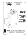
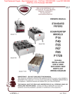
Total Restaurant Supply - https://totalsupply1.com - Toll Free 1-800-944-9304 - Local 507-288-9454
2940 Hwy 14 W, Rochester, MN 55901
381
WELLS BLOOMFIELD, LLC
10 Sunnen Dr., St. Louis, MO 63143
telephone: 314-678-6314
fax: 314-781-2714
www.wells-mfg.com
SUPPLEMENTAL
OWNERS MANUAL
VENTILATOR HOOD
SECTION
FRYER MODELS
WVAE30F
WVPE30F
WVAE55F
WVAE55FS
Includes
INSTALLATION
USE & CARE
EXPLODED VIEW
PARTS LIST
WIRING DIAGRAM
IMPORTANT: DO NOT DISCARD THIS MANUAL
This manual is considered to be part of the appliance and is to be given to the OWNER or
MANAGER of the restaurant, or to the person responsible for TRAINING OPERATORS of
this appliance. Additional manuals are available from your WELLS DEALER.
THIS MANUAL MUST BE READ AND UNDERSTOOD BY ALL PERSONS USING OR
INSTALLING THIS APPLIANCE. Contact your WELLS DEALER if you have any
questions concerning installation, operation or maintenance of this equipment.
p/n 2M-301603 Rev. F
M381
110429
Total Restaurant Supply - https://totalsupply1.com - Toll Free 1-800-944-9304 - Local 507-288-9454
2940 Hwy 14 W, Rochester, MN 55901
LIMITED WARRANTY STATEMENT
Unless otherwise specified, all commercial cooking
equipment manufactured by WELLS BLOOMFIELD, LLC is
warranted against defects in materials and workmanship
for a period of one year from the date of original installation
or 18 months from the date of shipment from our factory,
whichever comes first, and is for the benefit of the original
purchaser only.
THIS WARRANTY IS THE COMPLETE AND ONLY
WARRANTY, EXPRESSED OR IMPLIED IN LAW OR IN
FACT, INCLUDING BUT NOT LIMITED TO, WARRANTIES
OF MERCHANTABILITY OR FITNESS FOR ANY
PARTICULAR PURPOSE, AND/OR FOR DIRECT,
INDIRECT OR CONSEQUENTIAL DAMAGES IN
CONNECTION WITH WELLS BLOOMFIELD PRODUCTS.
This warranty is void if it is determined that, upon inspection
by an authorized service agency, the equipment has been
modified, misused, misapplied, improperly installed, or
damaged in transit or by fire, flood or act of God. It also
does not apply if the serial nameplate has been removed,
or if service is performed by unauthorized personnel.
The prices charged by Wells Bloomfield for its products
are based upon the limitations in this warranty. Seller’s
obligation under this warranty is limited to the repair
of defects without charge by a Wells Bloomfield factory
authorized service agency or one of its sub-service
agencies. This service will be provided on customer’s
premises for non-portable models. Portable models (a
device with a cord and plug) must be taken or shipped
to the closest authorized service agency, transportation
charges prepaid, for service. In addition to restrictions
contained in this warranty, specific limitations are shown in
the Service Policy and Procedure Guide. Wells Bloomfield
authorized service agencies are located in principal cities.
This warranty is valid in the United States and Canada and
void elsewhere. Please consult your classified telephone
directory, your foodservice equipment dealer or contact:
Wells Bloomfield, LLC
10 Sunnen Dr., St. Louis MO 63143 USA
phone (314) 678-6314 or fax (314) 781-2714
for information and other details concerning warranty.
SERVICE POLICY AND PROCEDURE GUIDE and ADDITIONAL WARRANTY EXCLUSIONS
2.
3.
4.
5.
6.
Resetting of safety thermostats, circuit breakers, over
load protectors, and/or fuse replacements are not covered by this warranty unless warranted conditions
are the cause.
All problems due to operation at voltages or phase other than specified on equipment nameplates are not covered by this warranty.
Conversion to correct voltage and/or phase must be the customer’s responsibility.
All problems due to electrical connections not made in accordance with electrical code requirements and wiring diagrams supplied with the equipment are not covered by this warranty.
Replacement of items subject to normal wear, to
include such items as knobs, light bulbs; and, normal maintenance functions including adjustments of
thermostats, adjustment of micro switches and
replacement of fuses and indicating lights are not
covered by warranty.
Damage to electrical cords and/or plug due to exposure
to excessive heat are not covered by this warranty.
Full use, care, and maintenance instructions supplied
with each machine. Noted maintenance and
preventative maintenance items, such as servicing and cleaning schedules, are customer responsibility. Those
miscellaneous adjustments noted are customer
responsibility. Proper attention to preventative
maintenance and scheduled maintenance procedures will prolong the life of the appliance.
7. Travel mileage is limited to sixty (60) miles from an Authorized Service Agency or one of its sub-service agencies.
8. All labor shall be performed during regular working
hours. Overtime premium will be charged to the buyer.
9. All genuine Wells replacement parts are warranted
for ninety (90) days from date of purchase on nonwarranty equipment. This parts warranty is limited only
to replacement of the defective part(s). Any use of
non-genuine Wells parts completely voids any
warranty.
10. Installation, labor, and job check-outs are not
considered warranty and are thus not covered by this warranty.
11. Charges incurred by delays, waiting time or operating restrictions that hinder the service technician’s ability to perform service are not covered by warranty. This includes institutional and correctional facilities.
SHIPPING DAMAGE CLAIM PROCEDURE
NOTE: For your protection, please note that equipment
in this shipment was carefully inspected and packaged
by skilled personnel before leaving the factory. Upon
acceptance of this shipment, the transportation company
assumes full responsibility for its safe delivery.
IF SHIPMENT ARRIVES DAMAGED:
1. VISIBLE LOSS OR DAMAGE: Be certain that any
visible loss or damage is noted on the freight bill or
express receipt, and that the note of loss or damage is
signed by the delivery person.
2. FILE CLAIM FOR DAMAGE IMMEDIATELY:
Regardless of the extent of the damage.
3.
CONCEALED LOSS OR DAMAGE: if damage is
unnoticed until the merchandise is unpacked, notify the transportation company or carrier immediately, and file “CONCEALED DAMAGE” claim with them. This should be done within fifteen (15) days from the date the delivery was made to you. Be sure to retain the container for inspection.
Wells Bloomfield cannot assume liability for damage or loss
incurred in transit. We will, however, at your request, supply
you with the necessary documents to support your claim.
xi
M381 2M-301603 Owners Manual (Supplemental) NFPA Hood
1.
Total Restaurant Supply - https://totalsupply1.com - Toll Free 1-800-944-9304 - Local 507-288-9454
2940 Hwy 14 W, Rochester, MN 55901
TABLE OF CONTENTS
INTRODUCTION
WARRANTY
SPECIFICATIONS
FEATURES & OPERATING CONTROLS
PRECAUTIONS & GENERAL INFORMATION
AGENCY LISTING INFORMATION
INSTALLATION
ANSUL® INSTALLATION & SETUP
OPERATION
CLEANING INSTRUCTIONS
MAINTENANCE INSTRUCTIONS
TROUBLESHOOTING SUGGESTIONS
EXPLODED VIEW & PARTS LIST
WIRING DIAGRAM
OTHER DOCUMENTATION
MAINTENANCE LOG
MSDS for Ansulex® Low pH
PARTS & SERVICE
CUSTOMER SERVICE DATA
xi
1
2
4
5
5
8
11
12
14
15
16
19
Thank You for purchasing this Wells
Bloomfield appliance.
26
27
29
29
For information regarding the
fryer section, please refer to the
associated fryer owners manual.
Proper installation, professional
operation and consistent
maintenance of this appliance will
ensure that it gives you the very best
performance and a long, economical
service life.
This supplemental manual contains
information and instructions pertinent
to the hood section of this ventless
appliance, and to its use and care.
DIMENSIONS
MODEL
WIDE
DEEP
HIGH
43.7”
(1110 mm)
76.4”
(1941 mm)
M381 2M-301603 Owners Manual (Supplemental) NFPA Hood
15.8” (402 mm)
ALL
20” (508 mm) including manual pull station
32” (812.8 mm) Including manual pull station and Ansul®
inspection window standoff
ELECTRICAL SPECIFICATIONS
MODEL
VOLTS
WATTS
AMPS
208 1ø
9,000
43.3
WFAE-30F
240 1ø
9,000
37.5
WVPE-30F
208 3ø
9,000
25.0 (L1, L2, L3)
240 3ø
9,000
22.0 (L1, L2, L3)
308-415V
9,300
WVAE-55F
208 3ø
17,000
47.8 (L1, L2, L3)
WVAE-55FS
240 3ø
17,000
41.0 (L1, L2, L3)
380-415V
17,400
WVAE-30F EU
WVPE-30F EU
WVAE-55F EU
WVAE-55FS EU
1
15.0 (L1)
13.0 (L2 & L3) 3 (N)
26.0 (L1)
24.0 (L2 & L3) 3 (N)
Total Restaurant Supply - https://totalsupply1.com - Toll Free 1-800-944-9304 - Local 507-288-9454
2940 Hwy 14 W, Rochester, MN 55901
FEATURES & OPERATING CONTROLS
BACK VIEW
v.10
v.6
v.7
v.8
SIDE VIEW
FRONT VIEW
VENTILATOR WARNINGLIGHT PANEL
VENTILATOR
POWER ON
CHECK
FILTERS
REPLACE
FILTERS
SERVICE
REQUIRED
WELLS
v.11
v.12
v.13
v.2
v.17
v.4
v.3
v.5
v.14
v.16
v.16
(ALTERNATE
LOCATION)
f.1
FRYER
v.15
OFF
FILTER
v.22
FRYER
WVAE-30,
WVAE-55 or
WVPE-30
f.9
f.18
v.7
f.21
IL2110
NOTE: Items beginning with “f. …” are part of the FRYER
Items beginning with “v. ...” are part of the VENTILATOR
FRYER
VENTILATOR
POWER ON
CHECK
FILTERS
WELLS
OFF
FILTER
2
REPLACE
FILTERS
SERVICE
REQUIRED
M381 2M-301603 Owners Manual (Supplemental) NFPA Hood
f.19
f.20
Total Restaurant Supply - https://totalsupply1.com - Toll Free 1-800-944-9304 - Local 507-288-9454
2940 Hwy 14 W, Rochester, MN 55901
FEATURES & OPERATING CONTROLS (continued)
ITEM
DESCRIPTION
POWER SWITCH
(FILTER-OFF-FRYER)
FRYER position energizes VENTILATOR POWER LIGHT and BLOWER. If,
within 10 seconds, there is sufficient airflow for proper operation, POWER
LIGHT will remain ON and fryer will operate.
v.2
VENTILATOR POWER
LIGHT (green)
Glows when FRYER POWER SWITCH in pressed to FRYER and adequate
airflow has been proven.
v.3
CHECK FILTERS LIGHT
(amber)
Glows when GREASE BAFFLE and/or HEPA FILTER are not properly
installed. When this light is lit, fryer is disabled.
v.4
REPLACE FILTERS
LIGHT (amber)
Glows if either CHARCOAL FILTER or HEPA FILTER are due for
replacement. Fryer will continue to operate, but filters must be changed in a
timely manner before they clog and disable the fryer.
v.5
SERVICE REQUIRED
LIGHT (red)
Glows when there is insufficient airflow for proper operation (either
CHARCOAL FILTER or HEPA FILTER, or both, plugged). When this light is lit,
fryer is disabled.
v.6
VENTILATOR BLOWER
Provides ventilation airflow.
v.7
FUSIBLE LINK LOCATION
FUSIBLE LINKS provide fire protection by melting at a pre-set temperature and
activating the fire suppression system.
v.8
FIRE SUPPRESSION
NOZZLE(S)
Disperse the fire suppression media.
FILTER PUMP MOTOR
Provides over-temperature protection for the FILTER PUMP MOTOR.
OVERLOAD RESET
Reset manually by pressing the red button.
f.1
f.9
M381 2M-301603 Owners Manual (Supplemental) NFPA Hood
FUNCTION
Ventilator discharge. DO NOT BLOCK.
v.10
VENTILATOR EXHAUST
COLLAR
v.11
v.12
v.13
CHARCOAL FILTER
HEPA AIR FILTER
GREASE BAFFLE
See page 10.
v.14
ANSUL® SYSTEM STATUS
INDICATOR
Indicates status of Ansul® fire suppression system
(i.e. COCKED or FIRED).
v.15
ACCESS TO AUTOLIFT
MOTOR
On fryers with automatic basket lifting device (WVAE-series) allows
servicing of lift mechanism.
v.16
MANUAL PULL STATION
Allows manual discharge of fire suppression system. Shown on left side, may
also be mounted on right side. IMPORTANT: PULL STATION must be field
installed by an ANSUL® technician.
v.17
f.18
f.19
f.20
GREASE CUP
DRIP PAN
STABILIZER
RIGID (REAR) CASTERS
Contains fire damper with pre-installed 285ºF (141ºC) fusible link.
Catches drippings from GREASE BAFFLE.
Catches any liquid draining from top of fryer section.
Prevents unit from tipping backwards.
Allows unit to be easily positioned by slightly lifting front of unit.
IMPORTANT
If a remote pull station is installed, both rear casters must be replaced with fixed legs in order to deter movement of unit.
MOVING AN APPLIANCE EQUIPPED WITH A REMOTE PULL STATION WILL DISCHARGE THE FIRE SUPPRESSION
SYSTEM.
f.21
FIXED (FRONT) LEGS
Allows the unit to be leveled.
v.22
ANSUL® INSPECTION
WINDOW
Allows the Ansul® components to be viewed without removing the back cover
(optional)
3
Total Restaurant Supply - https://totalsupply1.com - Toll Free 1-800-944-9304 - Local 507-288-9454
2940 Hwy 14 W, Rochester, MN 55901
PRECAUTIONS AND GENERAL INFORMATION
Shock hazard
All servicing requiring
access to non-insulated
electrical components must
be performed by a factory
authorized technician.
DO NOT open any access
panel which requires the use
of tools. Failure to follow this
warning can result in severe
electrical shock.
CAUTION:
Risk of
Damage
DO NOT connect or
energize this appliance
until all installation
instructions are read and
followed. Damage to the
appliance will result if these
instructions are not followed.
CAUTION:
Hot Surface
Exposed surfaces can be hot
to the touch and may cause
burns.
IMPORTANT:
The fryer is disabled when
the filters are plugged to the
point of insufficient airflow
for proper operation. Also,
the fryer is disabled if either
the HEPA filter or grease
baffle is removed.
It is the responsibility of
the store management to
maintain sufficient spares
of HEPA air filters to avoid
prolonged shutdown of
the fryer when this filter is
expended. Charcoal and
HEPA air filters cannot be
cleaned. Wells Bloomfield
assumes no liability for loss
of business due to filter
related shutdown.
This ventilator hood is part of an engineered system and is
intended for use in commercial establishments only.
This ventilator and attendant fryer are intended to prepare food for
human consumption. No other use is recommended or authorized by
the manufacturer or its agents.
Operators of this appliance must be familiar with the appliance use,
limitations and associated restrictions. Operating instructions must be
read and understood by all persons using or installing this appliance.
This ventilator hood system is designed to reduce odor emissions,
but will not completely eliminate all cooking odors. Air exchange
rates at the installation site must comply with the requirements of the
local jurisdictional authority. To ensure that odors do not accumulate,
recommended minimum air exchange is 400 cfm into and out of the
site.
Cleanliness of this appliance is essential to good sanitation. Read and
follow all included cleaning instructions and schedules to ensure the
safety of the food product.
Disconnect this appliance from electrical power before performing any
maintenance or servicing.
This appliance is not jet stream approved. Do not direct water jet
or steam jet at this appliance, or at any control panel or wiring. Do
not splash or pour water on, in or over any controls, control panel or
wiring. Do not wash floor around this appliance with water or steam
jet. Do not attempt to wash charcoal or HEPA air filters. Water will
cause their immediate failure and disable the fryer.
Exposed surfaces of this appliance can be hot to the touch and may
cause burns.
Cooking oil will be very hot when in use. Contact will cause severe
injury. Wear appropriate heat protective apron and gloves when using
this fryer.
Do not operate this appliance if the control panel is damaged. Do not
operate solid state versions of this appliance if the keypad section of
the control panel is torn or broken. Call your Authorized Wells Service
Agent for service.
Avoid storing flammable or combustible materials in, on or near the
appliance.
The technical content of this manual, including any wiring diagrams,
schematics, parts breakdown illustrations and/or adjustment
procedures, is intended for use by qualified technical personnel.
Any procedure which requires the use of tools must be performed by a
qualified technician.
This manual is considered to be a permanent part of the appliance.
This manual and all supplied instructions, diagrams, schematics, parts
breakdown illustrations, notices and labels must remain with the
appliance if it is sold or moved to another location.
This appliance is made in the USA. Unless otherwise noted, this
appliance has American sizes on all hardware.
4
M381 2M-301603 Owners Manual (Supplemental) NFPA Hood
WARNING:
Total Restaurant Supply - https://totalsupply1.com - Toll Free 1-800-944-9304 - Local 507-288-9454
2940 Hwy 14 W, Rochester, MN 55901
AGENCY LISTING INFORMATION
This appliance conforms to NSF Standard 4 for sanitation only if
installed in accordance with the supplied Installation Instructions and
maintained according to the instructions in this manual.
STD 4
E146882
This appliance is
and
Listed under UL File E146882.
E146882
INSTALLATION
UNPACKING & INSPECTION
Carefully remove the appliance from the carton. Remove all
protective plastic film, packing materials and accessories from the
appliance before connecting electrical power or otherwise performing
any installation procedure.
Carefully read all instructions in this manual before starting any
installation.
Read and understand all labels and diagrams attached to the
Fryer and to the ventilator.
Carefully account for all components and accessories before
discarding packing materials.
M381 2M-301603 Owners Manual (Supplemental) NFPA Hood
NOTE: DO NOT discard
the carton or other packing
materials until you have
inspected the appliance for
hidden damage and tested it
for proper operation.
Refer to SHIPPING DAMAGE
CLAIM PROCEDURE on the
inside front cover of this
manual.
WARNING:
Risk of injury
COMPONENTS
1 ea. 1 ea.
1 ea.
1 ea
Grease baffle
HEPA air filter
Charcoal filter
Grease cup
1 ea.
1 ea.
1 ea.
1 ea.
Fire suppression agent tank
Fire suppression agent (Ansulex® Low pH) 1.5 gal.
Fire suppression system charging cartridge
Manual pull station kit
(includes mounting hardware - must be installed by an authorized ANSUL® distributor only)
(as req’d)
Components and accessories specific to the fryer. Store
these components in a convenient place for later use
.Optional Ansul® inspection window and equipment standards.
5
Installation procedures must
be performed by a qualified
technician with full knowledge
of all applicable electrical
codes. Failure can result in
personal injury and property
damage.
IMPORTANT:
Fire suppression system must
be charged and certified by an
authorized Ansul® distributor.
Fryer will not operate until the
fire suppression system has
been charged.
Total Restaurant Supply - https://totalsupply1.com - Toll Free 1-800-944-9304 - Local 507-288-9454
2940 Hwy 14 W, Rochester, MN 55901
INSTALLATION (continued)
WARNING:
shock hazard
All servicing requiring access
to non-insulated electrical
components must be
performed by a factory
authorized technician.
DO NOT open any access
panel which requires the use
of tools. Failure to follow this
warning can result in severe
electrical shock.
CAUTION:
Risk of
Damage
DO NOT connect or energize
this appliance until all
installation instructions are
read and followed. Damage
to the appliance will result
if these instructions are not
followed.
SERVICE TECHNICIAN INSTALLATION NOTES
Installation and start up must be performed by an Authorized
Installation Company.
Installer must complete the WARRANTY REGISTRATION / FRYER
CHECKOUT form, and record fryer installation particulars on the
CUSTOMER SERVICE DATA form in this manual.
IT is the responsibility of thE installer to verify that
this FRYER and VENTILATOR installation is in compliance with
the specifications listed in this manual, with local code requirements,
and in accordance with the STANDARD FOR VENTILATON
CONTROL AND FIRE PROTECTION OF COMMERCIAL COOKING
OPERATIONS as detailed in N.F.P.A 96 (current edition).
Certain codes require fryers to be restrained with a tether or
other RESTRAINT DEVICE. It is the RESPONSIBILITY OF THE
INSTALLER to check with the authority having jurisdiction,
in order to ascertain the applicability of this requirement to this specific FRYER installation. Any restraint device must allow
access to the back and sides of the unit to provide for servicing and
maintenance, and must not interfere with the operation of the fire
suppression system.
SETUP
Setup the appliance only on a firm, level, non-combustible surface.
Verify local codes for requirements. Concrete, tile, terrazzo or metal
surfaces are recommended. Metal over combustible material may not
meet code for non-combustible surfaces.
Verify that the VENTILATOR HOOD ASSEMBLY is properly and
securely assembled to the FRYER before beginning the installation
procedure. Ventilator may have become dislodged during shipping or
unpacking.
IMPORTANT:
If a remote pull station is to
be used, replace the rear
casters with fixed legs.
Verify that the unit sits firmly on ALL FOUR legs / CASTERS.
With a spirit level, check that the appliance is level front-to-back and
side-to-side. With the adjustable legs, adjust as required to level the
appliance. In order to prevent tipping, legs must be adjusted such
that all four legs / casters are in firm contact with the floor.
Adjust rear stabilizer bars (see item f.19, page 2) to within 1/4” (6
mm)of floor to allow unit to be moved without tipping backwards.
Refer to the Installation Instruction Sheet for required clearances.
Maintain required clearances between the appliance and adjacent
combustible surfaces.
Inspection Window
For units equipped with the Ansul® component inspection window,
install the equipment stand-off bracket
6
M381 2M-301603 Owners Manual (Supplemental) NFPA Hood
Verify vertical clearances. Ventilator fryers require a minimum of 96”
(floor to overhead) to allow or adequate air circulation.
Total Restaurant Supply - https://totalsupply1.com - Toll Free 1-800-944-9304 - Local 507-288-9454
2940 Hwy 14 W, Rochester, MN 55901
INSTALLATION (continued)
ELECTRICAL INSTALLATION
Refer to the nameplate on the front of the fryer. Verify ELECTRICAL
SERVICE POWER. Voltage and phase must match the nameplate
specifications, and available electrical service amperage must meet or
exceed the specifications listed on page 1 of this manual.
•
•
Wiring must be no less than12 ga. solid copper wire, rated for at
least 75ºC.
Wire gauge, insulation type and temperature rating , as well
as type, size and construction of conduit, must meet or exceed applicable specifications of local codes and of the National
Electrical Code.
Fryers are shipped from the factory wired for 3Ø electrical service.
Refer to the three-phase wiring diagram included with this fryer, and
verify that field wiring conforms to this diagram .
NOTE: 30# FRYERS are field convertible to 1Ø.
If single-phase operation is required, refer to the 3-phase to 1-phase
Instructions included with the FRYER, and verify that both internal
wiring and field wiring conform to the included single-phase wiring
diagram.
WARNING
SHOCK HAZARD
Electrical connections must
be made by a licensed
electrician.
CAUTION:
Shock Hazard
The ground lug of this
appliance must be connected
to a suitable building ground.
IMPORTANT:
WVAE-55F and WVAE55FS units must not be
converted to single
phase operation.
Conversion of these units to
single phase operation
invalidates the UL listing and
will void the warranty.
IMPORTANT:
Contact a licensed electrician
to install and connect
electrical power to the
appliance.
M381 2M-301603 Owners Manual (Supplemental) NFPA Hood
IMPORTANT:
Damage due to being
connected to the wrong
voltage or phase is NOT
covered by warranty.
7
Total Restaurant Supply - https://totalsupply1.com - Toll Free 1-800-944-9304 - Local 507-288-9454
2940 Hwy 14 W, Rochester, MN 55901
INSTALLATION (continued)
FIRE HAZARD
Fire suppression system
must be charged and certified
by an authorized Ansul®
distributor.
DO NOT attempt to modify or
bypass the fire suppression
system.
An uncontrolled fire can
cause serious injury or death.
NOTE:
If the fire suppression system
is discharged, a buzzer will
sound continuously. The
fryer will remain inoperable
until the fire suppression
system is serviced, recharged
and reset by an authorized
Ansul® distributor.
Charging of the Ansul®
Fire Suppression system
must be in accordance with
Ansul® Design, Installation,
Recharge and Maintenance
Manual, #418087.
NOTE:
If a REMOTE MANUAL PULL
STATION is installed, moving
the FRYER for servicing may
cause the Ansul® system to
discharge. In this case, the
unit must only be installed
with four fixed legs
(i.e. remove rear casters and
replace with legs). Additional
legs may be ordered through
an Authorized Wells Service
Agency. See page 19.
FIRE SUPPRESSION SYSTEM INSTALLATION
FIRE SUPPRESSION SYSTEM is comprised of a container
of Ansulex® Low pH liquid fire suppression media, a system
pressurization canister and associated plumbing and controls.
Two FUSIBLE LINKS are utilized for automatic actuation, and a
MANUAL PULL STATION for manual actuation. Two NOZZLES
disperse the fire suppression media.
The hood is supplied with a field installed MANUAL PULL STATION,
which must be set-up at the time of the fryer installation by an
authorized Ansul® distributor. See below and following page for
installation details.
If the fryer is installed such that the supplied manual pull station cannot
be installed, a REMOTE MANUAL PULL STATION may be required by
local codes. Any such remote manual pull station must be installed by
an authorized Ansul® distributor in accordance with the Authority
Having Jurisdiction.
When the fire suppression system discharges, fryer heating element(s)
and controls are de-energized, and fire suppression media discharged.
Fire supression media will form an emulsion designed to both smother
and cool the oil.
The primary 450ºF FUSIBLE LINK is located on the frypot. This
link will melt and discharge the fire suppression system should both
the TEMPERATURE CONTROL THERMOSTAT and the HIGH LIMIT
CONTROL fail. The secondary 280ºF FUSIBLE LINK is located
in the filter plenum, and will protect against a fire in the plenum.
Either link melting will discharge the fire suppression media through
both NOZZLES, and cause a buzzer to sound.
The MANUAL PULL STATION and any similar REMOTE MANUAL
PULL STATION will activate the fire suppression system when the ring
on the pull station is pulled to its full extent.
8
M381 2M-301603 Owners Manual (Supplemental) NFPA Hood
DANGER
Total Restaurant Supply - https://totalsupply1.com - Toll Free 1-800-944-9304 - Local 507-288-9454
2940 Hwy 14 W, Rochester, MN 55901
INSTALLATION (continued)
DANGER
BURN HAZARD
HOT OIL SPILL
Any additional remote pull
station must not be installed on
the front or sides of the fryer
forward of the ventilator side
panels.
Discharge of the fire
extinguishing system into hot
oil will cause hot foam to spill
over from the frypot.
Serious burns and other
injuries can result from contact
with hot oil and from slipping in
spilled oil.
M381 2M-301603 Owners Manual (Supplemental) NFPA Hood
Exclusive Anti-Fire System
In the unlikely event that
both the temperature control
thermostat and hi-limit detector
fail, and the oil temperature
climbs above the safety limit,
the fire suppression system will
discharge, cooling the oil below
the oil’s (approximately) 540ºF
auto-ignition temperature,
and preventing a fire from
occurring.
9
Total Restaurant Supply - https://totalsupply1.com - Toll Free 1-800-944-9304 - Local 507-288-9454
2940 Hwy 14 W, Rochester, MN 55901
INSTALLATION (continued)
NOTE:
The GREASE BAFFLE and
HEPA AIR FILTER actuate
magnetic reed switches
when they are in their proper
positions. They must be
properly installed or the fryer
heater elements will not be
energized.
NOTE:
Remove the protective
plastic bag from the optional
charcoal filter before
installing.
Installing the filter without
removing the plastic bag
will block the air flow. This
will cause the ventilator to
shut down 10 seconds after
start-up, and the fryer will not
heat.
FILTER INSTALLATION
Remove the protective plastic bag from charcoal filter before installing.
Note air flow direction arrow on each filter, and verify that arrow points
toward plenum when filter is properly installed.
Install filters by inserting top of each into top filter support inside hood
assembly. Pivot bottom of each filter toward rear of hood assembly
and drop it into its respective bottom filter support. Seat each filter
firmly into the bottom filter support.
Install CHARCOAL FILTER first, followed by HEPA AIR FILTER.
Install GREASE BAFFLE last.
GREASE CUP & DRIP PAN INSTALLATION
Install GREASE CUP into brackets below grease baffle.
SLIP AND FALL
HAZARD
DO NOT operate fryer unless
drip pan is installed. Oil will
drip onto floor creating a
slipping hazard.
CAUTION
BURN HAZARD
Note: Failure to install GREASE CUP will allow grease and moisture
from GREASE BAFFLE to drop into FRYPOT, creating both a SAFETY
HAZARD (hot oil splatter) and a HEALTH HAZARD (contamination of
the cooking oil).
Install DRIP PAN into mounting bracket behind fryer door at lower right
front of fryer.
Note: Failure to install DRIP PAN will allow grease, moisture and
other liquids that accumulate on the fryer top panel to drip onto floor,
creating both a SAFETY HAZARD (slip and fall hazard) and a HEALTH
HAZARD (substance capable of supporting bacteria).
DO NOT operate fryer unless
grease cup is installed.
Moisture dripping into hot oil
will cause hot oil to splatter.
10
M381 2M-301603 Owners Manual (Supplemental) NFPA Hood
WARNING
Total Restaurant Supply - https://totalsupply1.com - Toll Free 1-800-944-9304 - Local 507-288-9454
2940 Hwy 14 W, Rochester, MN 55901
OPERATION
CAUTION:
Hot Surface
Exposed surfaces can be hot
to the touch and may cause
burns.
NOTE: Fryer must be operated in accordance with the instructions in
the accompanying FRYER OPERATION MANUAL.
During normal operation, VENTILATOR POWER ON light will be the only
light illuminated on ventilator warning light panel.
If the CHECK FILTERS light illuminates, check both GREASE BAFFLE
and the HEPA AIR FILTER for proper installation.
If REPLACE FILTERS light illuminates, replace both HEPA AIR
FILTER and CHARCOAL FILTER. Always replace both filters at the
same time.
NOTE: REPLACE FILTERS light is a warning that filters are nearing the
end of their service life. The fryer will continue to operate for a period of
time after REPLACE FILTER LIGHT turns ON to allow continued fryer
operation through a peak period. However, filters must be replaced
within a short time period or they will clog, disabling the fryer.
If SERVICE REQUIRED light illuminates, filters are restricted to the
point of insufficient airflow for proper operation. Fryer is shut down until
the underlying clogged filter situation has been corrected. Normally,
replacing both HEPA AIR FILTER and CHARCOAL FILTER will remedy
the condition. Reset the unit by turning FRYER POWER SWITCH to
OFF, then back to FRYER.
M381 2M-301603 Owners Manual (Supplemental) NFPA Hood
A failure of incoming electric power will cause a shut down of the unit.
Reset the unit by turning the FRYER POWER SWITCH to OFF, then
back to FRYER.
11
CAUTION:
Shock Hazard
DO NOT splash or pour water
or grease onto control panel
or wiring.
IMPORTANT:
The fryer is disabled when
REPLACE FILTERS light is
illuminated. Note that the
fryer cannot operate if the
HEPA air filter is removed.
It is the responsibility of
the store management to
maintain sufficient spares
of HEPA air filters to avoid
prolonged shutdown of
the fryer when this filter is
expended.
Charcoal and HEPA air filters
cannot be cleaned.
Wells Manufacturing
assumes no liability for loss of
business due to filter related
shutdown.
Total Restaurant Supply - https://totalsupply1.com - Toll Free 1-800-944-9304 - Local 507-288-9454
2940 Hwy 14 W, Rochester, MN 55901
CLEANING INSTRUCTIONS
Hot Surface
Exposed surfaces
can be hot to the touch and
may cause burns.
CAUTION:
Shock Hazard
DO NOT splash or pour water
or grease onto control panel
or wiring.
PRECAUTIONS: Disconnect unit from electric power and allow to cool
Cover frypot to prevent oil contamination
FREQUENCY:
Weekly
TOOLS:
Mild detergent, clean non-abrasive towels
NOTE: Ventilator section to be cleaned in conjunction with fryer
Refer to Fryer Operation Manual for fryer cleaning instructions.
1. Disconnect unit from electric power and allow to cool.
Cover frypot to prevent oil contamination.
2. Remove GREASE BAFFLE, GREASE CUP and DRIP PAN.
3. Empty GREASE CUP and DRIP PAN into an appropriate grease collection receptacle.
4. Clean GREASE BAFFLE, GREASE CUP and DRIP PAN in a sink or dishwasher using mild detergent and warm water.
5. Dry components with a clean non-abrasive cloth. Reinstall DRIP PAN, GREASE CUP, and GREASE BAFFLE.
6. Wipe exterior of fryer and ventilator with a clean cloth moistened with warm water and mild detergent. Rinse by wiping with a clean cloth moistened with warm water.
7. Uncover the frypot and reconnect unit to electric power.
Procedure is complete
12
M381 2M-301603 Owners Manual (Supplemental) NFPA Hood
CAUTION:
Total Restaurant Supply - https://totalsupply1.com - Toll Free 1-800-944-9304 - Local 507-288-9454
2940 Hwy 14 W, Rochester, MN 55901
CLEANING INSTRUCTIONS (continued)
PRECAUTIONS: Disconnect unit from electric power and allow to cool
Cover frypot to prevent oil contamination
FREQUENCY:
Monthly
TOOLS:
Mild detergent, clean non-abrasive towels
NOTE: Ventilator section to be cleaned in conjunction with fryer
Refer to Fryer Operation Manual for fryer cleaning instructions.
CAUTION:
Hot Surface
Exposed surfaces can be hot
to the touch and may cause
burns.
CAUTION:
Shock Hazard
1. Disconnect unit from electric power and allow to cool.
Cover frypot to prevent oil contamination.
2. Remove GREASE BAFFLE, HEPA AIR FILTER and CHARCOAL
FILTER.
3. Wipe interior of ventilator with a clean cloth moistened with warm water and mild detergent. Rinse by wiping with a clean cloth
moistened with warm water. DO NOT clean by spraying.
4. Dry ventilator thoroughly with a clean non-abrasive cloth. Reinstall CHARCOAL FILTER, HEPA AIR FILTER and GREASE BAFFLE..
5. Uncover the frypot and reconnect unit to electric power.
M381 2M-301603 Owners Manual (Supplemental) NFPA Hood
Procedure is complete
13
DO NOT splash or pour water
or grease onto control panel
or wiring.
IMPORTANT:
DO NOT wash HEPA air
filter or CHARCOAL filter.
Washing these filters will clog
them, and cause fryer to be
disabled.
IMPORTANT:
DO NOT clean interior of
ventilator by spraying.
Spraying can contaminate
the cooking oil, and may
cause internal damage
to the blower, operation
proofing system and/or fire
suppression system.
Clean by wiping only.
Total Restaurant Supply - https://totalsupply1.com - Toll Free 1-800-944-9304 - Local 507-288-9454
2940 Hwy 14 W, Rochester, MN 55901
REQUIRED MAINTENANCE
USE AND MAINTENANCE SHALL BE IN ACCORDANCE WITH THE
STANDARD FOR VENTILATION CONTROL AND FIRE PROTECTION
OF COMMERIAL COOKING OPERATIONS, N.F.P.A. 96 (current
edition).
3-MONTH MAINTENANCE:
Thoroughly clean entire HOOD PLENUM and BLOWER section.
6-MONTH MAINTENANCE:
Inspection and testing of total operation including FIRE DAMPER and
all SAFETY INTERLOCKS shall be performed by qualified service
personnel.
All FIRE SUPPRESION SYSTEM actuation components including
MANUAL PULL STATION and any REMOTE MANUAL PULL STATION
must be inspected for proper operation in accordance with the
maintenance schedule published in ANSUL® R-102 SYSTEM DESIGN,
INSTALLATION, RECHARGE AND MAINTENANCE MANUAL (418087).
On WVAE-Model fryers, open the rear cover access door
and lubricate the lift worm threads with molybdenum disulfide
grease (see item v.15 page 2) .
ANNUAL (12-MONTH) MAINTENANCE:
FIRE SUPRESSION SYSTEM FUSIBLE LINKS must be replaced.
NOZZLES and MANUAL PULL STATION must be cleaned in
accordance with ANSUL® R-102 SYSYTEM DESIGN, INSTALLATION,
RECHARGE AND MAINTENANCE MANUAL (418087).
12-YEAR MAINTENANCE:
The FIRE SUPRESSION AGENT TANK and ¼” FLEX HOSE must be
hydrostatically tested, and the FIRE EXTINGUISHING AGENT
must be replaced in accordance with the maintenance schedule
published in ANSUL® R-102 SYSTEM (STANDARD UL 300 LISTED).
This maintenance to be performed by qualified Ansul® service
personnel only.
14
M381 2M-301603 Owners Manual (Supplemental) NFPA Hood
IMPORTANT:
A signed and dated FRYER
HOOD MAINTENANCE LOG
must be maintained on the
premises, and shall be made
available for inspection by the
authority having jurisdiction
upon request.
See page 15.
Total Restaurant Supply - https://totalsupply1.com - Toll Free 1-800-944-9304 - Local 507-288-9454
2940 Hwy 14 W, Rochester, MN 55901
TROUBLESHOOTING SUGGESTIONS
Possible Cause
Problem
Unit will not operate
(no indicators lights lit)
Unit will not operate
Suggested Remedy
Reconnect to electric power
Disconnected from electric power
Reset circuit breaker for unit
Fire suppression system not set
Contact an authorized Ansul® distributor for repairs
CHECK FILTER light lit
HEPA air filter or grease baffle not in position
Properly install HEPA filter and grease baffle
REPLACE FILTERS light lit
HEPA air filter and charcoal filters nearing end of service
life
Arrange to replace both HEPA and charcoal filters in a
timely manner
SERVICE REQUIRED light lit
HEPA air filter and charcoal filters plugged
Replace both HEPA and charcoal filters
(fryer not operating)
Fire damper in exhaust collar has closed
Contact an authorized Wells service agent for repairs
One or more vacuum sensing lines or ports plugged
Contact an authorized Wells service agent for repairs
(buzzer sounds)
NOTE: If, after 10 seconds, there is insufficient airflow for proper operation, SERVICE REQUIRED light will illuminate
and fryer will be de-energized.
Press FRYER POWER SWITCH to OFF, then back to FRYER to reset system.
NOTE:
FILTERS are the only user serviceable components
in this ventilator hood system. For all problems that
cannot be remedied by servicing the filters, contact:
Fryer or ventilator section - authorized Wells
vice agency
ser-
M381 2M-301603 Owners Manual (Supplemental) NFPA Hood
Fire suppression system - authorized Ansul®
distributor
IMPORTANT:
Contact ANSUL® for fire suppression system installation, set-up and service:
Ansul Incorporated
1-800-TO-ANSUL (1-800-862-6785)
One Station Street
Marinette, WI 54143-2542
website http;//www.ansul.com
IMPORTANT:
Parts used in the Ansul® fire suppression system are not serviceable by the owner/operator.
Procedures for servicing fire suppression equipment are described in:
ANSUL® R-102 SYSTEM DESIGN, INSTALLATION, RECHARGE AND MAINTENANCE MANUAL
(418087, current edition)
NOTE:
ANSUL® Manual 41807 and Wells Bulletin 301646 are intended for use by authorized Ansul® service
personnel only.
15
Total Restaurant Supply - https://totalsupply1.com - Toll Free 1-800-944-9304 - Local 507-288-9454
2940 Hwy 14 W, Rochester, MN 55901
EXPLODED VIEW PARTS LIST
CABINET AND HOOD SECTION COMPONENTS
DAMPER ASSY
2V-301187
COVER PLUMBING
M3-301185
BLOWER ASSY
DD-501224
Optional
Viewport & Standoff
PANEL LIGHT
M3-301262
LIGHT, SIGNAL
GREEN 2J-35697
LIGHT, SIGNAL
AMBER 2J-30516
LIGHT, SIGNAL
RED
2J-31157
FILTER, CHARCOAL
5M-22403
SEE PAGE 17
SEE PAGE 17
FILTER, HEPA
5M-22402
SEE PAGE 17
SEE PAGE 4 - VACUUM AND
INTERLOCK COMPONENTS
HANDLE, FILTER
N1-301435
SEE PAGE 18
GREASE BAFFLE
5M-22695
SEE PAGE 5
ANSUL® COMPONENTS
VACUUM AND
INTERLOCK
COMPONENTS
FUSIBLE LINK 280ºF
TYPE K
501378
HOLDER, FUSIBLE
LINK
M3-47399
FUSIBLE LINK 450ºF
TYPE K
2E-47274
(LOCATION VARIES
BETWEEN FRYER
MODELS)
GREASE CUP
M3-301189
PANEL RIGHT LEFT STD
DD-302173
PANEL SIDE LEFT STD
DD-302174
IL2114A
16
M381 2M-301603 Owners Manual (Supplemental) NFPA Hood
SEE PAGE
17 4
SEE PAGE
Total Restaurant Supply - https://totalsupply1.com - Toll Free 1-800-944-9304 - Local 507-288-9454
2940 Hwy 14 W, Rochester, MN 55901
EXPLODED VIEW PARTS LIST
VACUUM AND INTERLOCK SYSTEM COMPONENTS
QUICK-SEAL ADAPTER, 1/4”
(Ansul p/n 78195)
VACUUM SWITCH
REPLACE FILTER
2E-301380
TUBE VINYL
3/16” ID x 18-1/2” L
M3-303031
BLOWER ASSEMBLY
2U-302984
VACUUM SWITCH
SHUTDOWN
2E-301379
M381 2M-301603 Owners Manual (Supplemental) NFPA Hood
RETAINER RING
.122 ID 2C-40030
GR
EA
SE
BA
MAGNET, PERMANEMT
2R-43948
SWITCH, PROXIMITY
M3-301409
FFL
E
HE
PA
F
ILT
ER
BUSHING
2K-301448
PAWL, INTERLOCK
NFPA HOOD M3-301588
COVER INTLOCK
M3-301260
17
IL2103
Total Restaurant Supply - https://totalsupply1.com - Toll Free 1-800-944-9304 - Local 507-288-9454
2940 Hwy 14 W, Rochester, MN 55901
EXPLODED VIEW PARTS LIST
FIRE DETECTION AND SUPPRESSION SYSTEM COMPONENTS
FOR USE ONLY BY AUTHORIZED
ANSUL© SERVICE PERSONNEL
ref. ADAPTER, QUICK-SEAL
1/2” CONDUIT ADAPTER
ANSUL© p/n 79152 (typical)
Refer to Ansul© part no. 418078-05
R-102 Restaurant Fire Suppression
System Design, Installation,
Recharge and Maintenance
FUSIBLE LINK 280ºF
MODEL K 2E-301378
ref. NOZZLE 1N
ANSUL© p/n 419335
FRON
ref. ADAPTER, QUICK-SEAL 3/8”
ANSUL© p/n 77284 (typical)
T OF
ref. NOZZLE 3N
ANSUL© p/n 419338
UNIT
ref. PULLEY ELBOW
ANSUL© p/n 423250
(typical)
ref. MOUNTING BRACKET
RELEASE MECHANISM
R-102 ANSUL© p/n 79493
(NOT SHOWN)
CARTRIDGE LT-20-R
ANSUL© p/n 67099
(NOT SHOWN)
MICROSWITCH 2E-47273
TERM.BLOCK 2E-53068
ref. CABLE, WIRE ROPE
ANSUL© p/n 15821 (50’/15m)
79653 (500’/152m) (typical)
ASSY, PULL STATION
ANSUL©
2O-301389
(NOT SHOWN)
ANSULEX ® EXTINGUISHING
AGENT 1.5 GAL.
ANSUL© p/n 79694
HOLDER, FUSIBLE
LINK
M3-47399
insi
de
out
side
insid
e
Cable sits in
groove in
pulley
ANSUL© p/n 423250
DETAIL
Seal with
Teflon tape
side
Fiber
washer
is always
on the inside
ANSUL© p/n 77284
DETAIL
wall of fryer
out
cabinet wall
Fiber
washer
is always
on the inside
Conduit passes completely
through the fitting, and is
sealed with the compression
washer and nut
Seal with
Teflon tape
ANSUL© p/n 79152
DETAIL
con
dui
t
IL2113
18
M381 2M-301603 Owners Manual (Supplemental) NFPA Hood
ref. TANK 1.5 GAL ANSULEX®
ANSUL©p/n 429864
FUSIBLE LINK 450ºF
MODEL K
2E-47274
(LOCATION DIFFERS
BETWEEN FRYER
MODELS)
Total Restaurant Supply - https://totalsupply1.com - Toll Free 1-800-944-9304 - Local 507-288-9454
2940 Hwy 14 W, Rochester, MN 55901
WIRING DIAGRAM
WVAE-55F & VAE-55F
3Ø, 208V OR 240V, 17KW
REPLACE
FILTER
SERVICE
REQUIRED
CHECK
FILTER
46
VENTILATOR
POWER
OPTIONAL SOLID
SHORTENING MELT
OPTION
24 V PLUMBING
HEATER TAPE
53
50VA X-FORMER
50
51
51
44
49
48
47
45
41
1/4 INS
MALE
1/4 INS
FEMALE
HEPA
FILTER INTLK
24V
24 V FILTER PAN
HEATER PAD
BLOWER
MOTOR
1/4 INS
MALE
M
WIRE
NUT(2)
1/4 INS
MALE
41
AIR FLOW
INTLK.
INTERVAL TIMER
3
C
BAFFLE FILTER
INTLK
56
52
2
44
44
BLD'G ALARM RELAY
(2&4) BEHIND REAR
BOTTOM COVER ON
RIGHT HAND SIDE OF
BOTTOM PANNEL.
C
54
55
58
NO
1
NC
45
1/4 INS
FEMALE
56
57
REPLACE
FILTER
SWITCH
1/4 INS
FEMALE
BUZZER
220V 60HZ
44
58
RED
40
42
COIL
59
BROWN
M-S
1/4 INS
MALE
1L1
E-SAFE
RELAY
15
1
2
3
10
1
1L2
2
3
1L1
1
6
L3
1L2
2
5
L2
1L3
3
4
L1
M381 2M-301603 Owners Manual (Supplemental) NFPA Hood
POWER
SWITCH
40
8A
4
3
COM
43
EXTERNAL INTERLOCK
(REMOVE FOR
EXTERNAL CONTROL)
JUMPER
8
9
11
8
FUSES (2)
15A MAX
29
BUZZER
SWITCH
35
33
30
TERMINATE TIMER MOTOR LEADS
W/ 3/16" PO TERM.(2C-38898)
23
BUZZER
LIGHT
9A
C
TERMINAL
BLOCK
2
NO
5
NC
14
9
26
SAFETY
CONTACTOR
1/4 INS
FEMALE
7
"HEAT"
LIGHT
13
27
41
1L3
1
59
BLACK
32
BUZZER
31
20
34
42
22
24
TIMER
17
19
"POWER"
LIGHT
15
14
COOK
LIGHT
18
HI LIMIT
THERMOSTAT
TEMPERATURE
CONTROL
THERMOSTAT
26
GREEN
16
36
27
FILTER
PUMP
43
21
WHITE
LIMIT
SWITCHES
INSIDE
MOTOR
HOUSING
GREEN
BLACK
RED
BASKET LIFT
ACTUATOR
NOM AMPS PER LINE
THREE PHASE
L1
L2
L3
208
48
48
47
240
42
42
41
VOLTS
17
18
60 HZ
2M-Z13151~
19
Total Restaurant Supply - https://totalsupply1.com - Toll Free 1-800-944-9304 - Local 507-288-9454
2940 Hwy 14 W, Rochester, MN 55901
WIRING DIAGRAM
SERVICE
REQUIRED
LIGHT
(RED)
24 V PLUMBING
HEATER TAPE
CHECK
FILTER
LIGHT
(AMBER)
REPLACE
FILTER
LIGHT
(AMBER)
50VA X-FORMER
46
VENTILATOR
POWER
LIGHT
(GREEN)
WVAE-55FS & VAE-55FS
3Ø, 208V OR 240V, 17KW
53
50
51
24V
51
41
44
47
45
24 V FILTER PAN
HEATER PAD
BLOWER
MOTOR
WIRE
NUT(2)
OPTIONAL SOLID
SHORTENING MELT
OPTION
NOT UL LISTED
ON SINGLE PHASE
AIR FLOW
VACUUM
SWITCH
(LARGE)
INTERVAL TIMER
56
52
2
1
NC
*
*
56
3
BAFFLE FILTER
MAGNET OPERATED
SWITCH
HEPA FILTER
MAGNET OPERATED
SWITCH
41
57
C
NO
44
58
44
44
HOOD
UPPER CONTROL BOX
RED
42
1L2
2
1L3
3
1L1
1
1L2
2
1L3
3
2
5
NO
NC
59
1/4 INS
MALE
HOOD
1
1
4
3
BROWN
8500W ELEMENT
1L1
59
BUZZER
220V 60HZ
BLACK
M-S
41
BLD'G ALARM RELAY
(2&4) BEHIND REAR
BOTTOM COVER ON
RIGHT HAND SIDE OF
BOTTOM PANEL.
C
54
40
58
55
45
COM
1/4 INS
FEMALE
UPPER CONTROL BOX
43
8500W ELEMENT
E-SAFE
RELAY
38
S
37
15
S
1
2
9
FUSE
15A MAX
11
SAFETY
CONTACTOR
14
42
13
C
3
2
1
6
5
4
9
8
7
6
POWER
SWITCH
+
22
COM
12
11
10
5
9
6
3
8
5
2
7
4
1
UP
-
+
24V
HI LIMIT
THERMOSTAT
3
2
1
THERMOCOUPLE
16
-
RED
21
WHITE
34
+
(BASKET DOWN)
SOLID STATE
RELAY
AUDIBLE
ALARM
31
22
19
1
30
2
AC
-
4
+
DC
1
20
30
UP
10
18
AC
LIMIT SWITCHES
INSIDE MTR HSG
-
4
DC
23
+
3
31
WHITE
(COM)
BASKET LIFT
ACTUATOR
32
2
BOTTOM
16
FILTER
PUMP
33
3
(BASKET UP)
SOLID STATE
RELAY
S
EXTERNAL INTERLOCK
TERMINAL BLOCK
(REMOVE JUMPER
WHEN EXTERNAL
CONTROL IS USED)
43
TOP
17
DOWN
26
27
23
21
CONTROLLER
TRANSFORMER
240V
30
JUMPER
8
14
4
208V
L2
L1
CONTROLLER
12
8A
25
4
FUSE
15A MAX
16
40
L3
5
7
10
26
6
3
9
27
MAIN
TERMINAL X
BLOCK
(DN)
BLACK
(UP)
RED
17
S S
18
NOTE: -WIRE NUMBERS 16, 17 AND 18 ARE ROUTED THRU
A 3/8 INCH FLEXIBLE CONDUIT.
-WIRE NUMBERS 26, 27, AND 36 ARE ROUTED THRU
A 3/8 INCH FLEXIBLE CONDUIT.
*
20
VOLTS
208
L1
48
240
42
TWO MAGNET SWITCHES LOCATED BEHIND TOP REAR PANEL.
FRYER RATING
AMPS
L3
L2
48
47
42
50-60 HZ
41
2M-Z13152-3~
M381 2M-301603 Owners Manual (Supplemental) NFPA Hood
15
GREEN
X
SPARK
QUENCHER
(SNUBBER)
1/4 INS
FEMALE
GREEN
S
REPLACE
FILTER
VACUUM
SWITCH
(SMALL)
1/4 INS
MALE
M
1/4 INS
MALE(2)
1/4 INS
FEMALE(2)
49
48
Total Restaurant Supply - https://totalsupply1.com - Toll Free 1-800-944-9304 - Local 507-288-9454
2940 Hwy 14 W, Rochester, MN 55901
WIRING DIAGRAM
SERVICE
REQUIRED
LIGHT
(RED)
24 V PLUMBING
HEATER TAPE
CHECK
FILTER
LIGHT
(AMBER)
REPLACE
FILTER
LIGHT
(AMBER)
50VA X-FORMER
46
VENTILATOR
POWER
LIGHT
(GREEN)
WVAE-55FS & VAE-55FS
1Ø, 208V OR 240V, 11.3KW
53
50
51
24V
51
41
44
45
24 V FILTER PAN
HEATER PAD
BLOWER
MOTOR
WIRE
NUT(2)
OPTIONAL SOLID
SHORTENING MELT
OPTION
S
X
REPLACE
FILTER
VACUUM
SWITCH
(SMALL)
SPARK
QUENCHER
(SNUBBER)
NOT UL LISTED
ON SINGLE PHASE
1/4 INS
MALE
M
1/4 INS
FEMALE
57 INTERVAL TIMER
3
*
*
56
AIR FLOW
VACUUM
SWITCH
(LARGE)
56
52
2
1
NC
BAFFLE FILTER
MAGNET OPERATED
SWITCH
HEPA FILTER
MAGNET OPERATED
SWITCH
41
C
NO
44
58
55
58
44
HOOD
44
UPPER CONTROL BOX
RED
42
1L3
3
1L1
1
1L3
3
2
5
NO
NC
59
1/4 INS
MALE
8500W ELEMENT
1
1
4
3
BROWN
HOOD
1L1
59
BUZZER
220V 60HZ
BLACK
M-S
41
BLD'G ALARM RELAY
(2&4) BEHIND REAR
BOTTOM COVER ON
RIGHT HAND SIDE OF
BOTTOM PANEL.
C
54
40
45
1/4 INS
MALE(2)
1/4 INS
FEMALE(2)
49
48
47
COM
1/4 INS
FEMALE
UPPER CONTROL BOX
43
8500W ELEMENT
15
E-SAFE
RELAY
38
S
37
15
S
11
9
FUSE
15A MAX
MAIN
TERMINAL X
BLOCK
SAFETY
CONTACTOR
14
5
L3
4
L2
3
L1
1
7
9
10
27
42
12
13
C
40
2
1
6
5
4
9
8
7
6
5
12
11
10
9
6
3
8
5
2
4
1
14
4
25
POWER
SWITCH
+
22
COM
7
UP
-
+
208V
30
24V
3
2
1
THERMOCOUPLE
16
-
RED
21
WHITE
(BASKET DOWN)
SOLID STATE
RELAY
31
1
30
2
AC
17
-
4
+
DC
1
20
30
UP
10
18
AC
LIMIT SWITCHES
INSIDE MTR HSG
-
4
DC
23
+
3
31
WHITE
(COM)
BASKET LIFT
ACTUATOR
32
2
BOTTOM
16
FILTER
PUMP
33
3
(BASKET UP)
SOLID STATE
RELAY
S
EXTERNAL INTERLOCK
TERMINAL BLOCK
(REMOVE JUMPER
WHEN EXTERNAL
CONTROL IS USED)
43
TOP
19 DOWN
(DN)
BLACK
(UP)
RED
GREEN
34
+
AUDIBLE
ALARM
22
26
27
23
21
CONTROLLER
TRANSFORMER
240V
GREEN
M381 2M-301603 Owners Manual (Supplemental) NFPA Hood
8A
3
8
HI LIMIT
THERMOSTAT
CONTROLLER
16
26
JUMPER
FUSE
15A MAX
17
S S
18
NOTE: -WIRE NUMBERS 16, 17 AND 18 ARE ROUTED THRU
A 3/8 INCH FLEXIBLE CONDUIT.
-WIRE NUMBERS 26, 27, AND 36 ARE ROUTED THRU
A 3/8 INCH FLEXIBLE CONDUIT.
*
FRYER RATING
VOLTS AMPS (SINGLE PHASE)
L2
55
208
240
TWO MAGNET SWITCHES LOCATED BEHIND TOP REAR PANEL.
21
50-60 HZ
47
2M-Z13152-1~
Total Restaurant Supply - https://totalsupply1.com - Toll Free 1-800-944-9304 - Local 507-288-9454
2940 Hwy 14 W, Rochester, MN 55901
WIRING DIAGRAM
WIRING DIAGRAM FOR VPE-30F & WVPE-30F
208V OR 240V, 9KW
SINGLE OR 3 PHASE - WIRED 3 PHASE AS SHOWN
VENTILATOR
POWER
CHECK
FILTER
REPLACE
FILTER
SERVICE
REQUIRED
44
53
50
45
51
51
41
48
46
1/4 INS
MALE
47
BLOWER
MOTOR
1/4 INS
FEMALE
M
1/4 INS
MALE
HEPA
FILTER INTLK
WIRE NUT
(2)
56
3
C
NC
BAFFLE FILTER
INTLK
BUZZER 220V 60HZ
58
NO
52
2
54
1
42
1/4 INS
FEMALE
AIR FLOW
INTLK.
57
REPLACE
FILTER
SWITCH
1/4 INS
MALE
1/4 INS
FEMALE
49
44
C
40
59
56
1
55
45
58
COIL
44
BLACK
MICRO
SWITCH
HOOD
ON-OFF
SWITCH
ON-OFF
AMBER
C
40
24
14
42
BROWN
1/4 INS
MALE
10
MICRO
SWITCH
N.C.
COM
N.O.
3
2
4
1
M
18
25
UPPER CONTROL BOX
LOWER CONTROL BOX
17
11
7
1/4 INS
FEMALE
26
BUZZER
9
19
8
22
COOK
LIGHT
AMBER
HEAT-ON
AMBER
COM
BLD'G ALARM RELAY (2&4)
BEHIND REAR BOTTOM
COVER ON RIGHT HAND SIDE
OF BOTTOM PANEL.
RED
UPPER CONTROL BOX
NO
4
3
59
41
2
5
NC
43
15
12
12
CONTROLLER THERMOSTAT
32
4
1
5
2
22
6
3
21
1L2
11
1L3
HI-LIMIT
THERMOSTAT
L1 HEATER ELEMENT
1L3
22
L1 L2
19
12
1L1
1L2
41
1L1
31
L2 HEATER ELEMENT
FILTER MOTOR
L3
FILTER
ON-OFF
SWITCH
24
TERMINAL
BLOCK
M
23
L3 HEATER ELEMENT
FILTER
21
TERMINAL
BLOCK
NOM AMPS PER LINE
VOLTS
L1
THREE PHASE
L2
L3
208
26
25
26
44
240
23
22
23
39
3
1
ONE
PHASE
7
1L1
60 HZ
20
1
4
1L2
1L3
2
5
3
6
SINGLE PHASE
WIRING
L1
22
CONTACTOR
11
2
REV. F P/N 2M-301412
SINGLE PHASE
CONVERSION
L2
L3
M381 2M-301603 Owners Manual (Supplemental) NFPA Hood
CONTACTOR
20
Total Restaurant Supply - https://totalsupply1.com - Toll Free 1-800-944-9304 - Local 507-288-9454
2940 Hwy 14 W, Rochester, MN 55901
M381 2M-301603 Owners Manual (Supplemental) NFPA Hood
WIRING DIAGRAM
23
Total Restaurant Supply - https://totalsupply1.com - Toll Free 1-800-944-9304 - Local 507-288-9454
2940 Hwy 14 W, Rochester, MN 55901
WIRING DIAGRAM
REPLACE
FILTER
SERVICE
REQUIRED
CHECK
FILTER
46
WVAE-30F & VAE-30F
VENTILATOR
POWER
1Ø OR 3Ø, 208V OR 240V, 9KW w/BUZZER
WIRED 3Ø AS SHOWN
53
50
51
51
44
49
48
47
45
BLOWER
MOTOR
WIRE
NUT(2)
41
M
1/4 INS
MALE
1/4 INS
FEMALE
AIR FLOW
INTLK.
INTERVAL TIMER
3
C
BAFFLE FILTER
INTLK
56
52
2
58
NO
1
NC
45
1/4 INS
FEMALE
41
56
57
REPLACE
FILTER
SWITCH
1/4 INS
MALE
1/4 INS
MALE
1/4 INS
FEMALE
HEPA
FILTER INTLK
44
C
54
55
44
BUZZER
220V 60HZ
44
58
HOOD
UPPER CONTROL BOX
RED
40
42
COIL
59
HOOD
1/4 INS
MALE
1/4 INS
FEMALE
4
3
BUZZER
SWITCH
COM
BLD'G ALARM RELAY
(2&4) BEHIND REAR
BOTTOM COVER ON
RIGHT HAND SIDE OF
BOTTOM PANNEL.
UPPER CONTROL BOX
TERMINATE TIMER MOTOR LEADS
W/ 3/16" INS PO TERM (2C-38898)
2
NO
5
NC
BROWN
M-S
41
1
59
BLACK
BUZZER
LIGHT
31
35
25
33
HEAT-ON
LIGHT
COOK
LIGHT
26
43
17
TIMER
31
40
18
8
11
11
LOWER CONTROL BOX
FUSES (2)
15A MAX
4
1
5
2
3
6
32
31
M
22
21
12
11
41
22
FILTER
SWITCH
L2
HEATER
ELEMENT
1L3
L3
HEATER
ELEMENT
23
FILTER
SINGLE PHASE CONVERSION
NOM AMPS PER LINE
ONE PHASE
THREE PHASE
L3
L2
208
27
25
27
45
240
24
22
24
40
43
HI LIMIT
THERMOSTAT
FILTER
MOTOR
21
24
12
1L2
M
1/4 INS
FEMALE
15
L1
HEATER
ELEMENT
1L1
1L1
1L2
1L3
20
L1 L2 L3
TERMINAL
BLOCK
1/4 INS
MALE
12
19
7
L1
LIFT
MOTOR
15
CONTROLLER
THERMOSTAT
CONTACTOR
VOLTS
LIFT
MOTOR
POSITION
SWITCH
LIFT
MOTOR
HOUSING
UPPER CONTROL BOX
22
24
NC
32
7A
C
10
15
20A
NO
14
9
8
MOTOR LEAD TERMINATED
WITH A 3/16 INS STPO
32
42
C
24
BUZZER
25
POWER
LIGHT
TERMINAL BLOCK
60 HZ
CONTACTOR
3
1
2
7
1L1
1
4
2
5
3
6
1L2
1L3
20
SINGLE PHASE
WIRING
L1
24
L2
L3
2M-Z13148B
M381 2M-301603 Owners Manual (Supplemental) NFPA Hood
POWER
SWITCH
34
36
M381 2M-301603 Owners Manual (Supplemental) NFPA Hood
Total Restaurant Supply - https://totalsupply1.com - Toll Free 1-800-944-9304 - Local 507-288-9454
2940 Hwy 14 W, Rochester, MN 55901
25
M381 2M-301603 Owners Manual (Supplemental) NFPA Hood
Total Restaurant Supply - https://totalsupply1.com - Toll Free 1-800-944-9304 - Local 507-288-9454
2940 Hwy 14 W, Rochester, MN 55901
26
M381 2M-301603 Owners Manual (Supplemental) NFPA Hood
Total Restaurant Supply - https://totalsupply1.com - Toll Free 1-800-944-9304 - Local 507-288-9454
2940 Hwy 14 W, Rochester, MN 55901
27
Total Restaurant Supply - https://totalsupply1.com - Toll Free 1-800-944-9304 - Local 507-288-9454
2940 Hwy 14 W, Rochester, MN 55901
M381 2M-301603 Owners Manual (Supplemental) NFPA Hood
NOTES
28
Total Restaurant Supply - https://totalsupply1.com - Toll Free 1-800-944-9304 - Local 507-288-9454
2940 Hwy 14 W, Rochester, MN 55901
PARTS & SERVICE
DESCRIPTION
LEG KIT, REAR, WVAE, WVPE
HEPA AIR FILTER
CHARCOAL FILTER
PART NO.
5M-22692
5M-22402
5M-22403
IMPORTANT: Use only
factory authorized service parts
and replacement filters.
For factory authorized
service, or to order factory
authorized replacement parts,
contact your Wells authorized
service agency, or call:
Wells Bloomfield, LLC
10 Sunnen Dr.,
St. Louis MO 63143 USA
Service Dept.
phone: (314) 678-6314
fax:
(314) 781-2714
M381 2M-301603 Owners Manual (Supplemental) NFPA Hood
Service Parts Department
can supply you with the name
and telephone number of
the WELLS authorized
service agency
nearest you.
CUSTOMER SERVICE DATA
please have this information available if calling for service
RESTAURANT _____________________________ LOCATION _____________
INSTALLATION DATE ________________________ TECHNICIAN ___________
SERVICE COMPANY ________________________________________________
ADDRESS ___________________________ STATE ______ ZIP__________
TELEPHONE NUMBER (_____)_____-_________
EQUIPMENT MODEL NO. _______________
EQUIPMENT SERIAL NO. _______________
VOLTAGE: (check one)
208
240
380-415
29
Total Restaurant Supply - https://totalsupply1.com - Toll Free 1-800-944-9304 - Local 507-288-9454
2940 Hwy 14 W, Rochester, MN 55901
WELLS BLOOMFIELD, LLC
10 Sunnen Dr., St. Louis, MO 63143
telephone: 314-678-6314
fax: 314-781-2714
www.wells-mfg.com