1
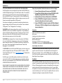
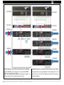
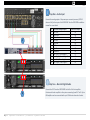
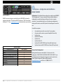
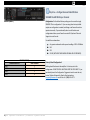
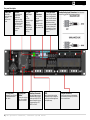
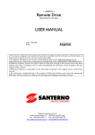
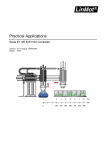
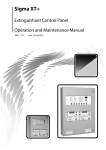
JBL SYNTHESIS®
SDA8300
SDA4600
AMPLIFIER
SYSTEM INSTALLATION GUIDE
May, 2014
P/N 070-90018 (rev A.0)
Read Me First!
IF YOU READ NOTHING ELSE IN THIS GUIDE READ THIS INFORMATION:
The SDA amplifiers come pre-configured to work with the SDEC4500P using
the BLU-LINK digital audio signal over Cat5e Ethernet cables. The amplifiers
should not be connected to the home network. Analog Audio input comes
IN on the SDEC4500P (up to 12 channels) and OUT on the SDA8300 and/or
SDA4600 without going through any Digital to Analog conversions (up to 20
Channels as standard, expandable to 128 channels).
Two alternate configurations are selected by using the included selection
trigger that plugs into the GPIO input on the rear panel. These are labeled
“Configuration 2” and “Configuration 3” on the plug.
The SDA8300 amplifier ships configured for a simple 7-channel system. The
SDA8300 can access two (2) additional configurations. Using combinations
of these configurations allows the system to output from a simple 7 x 300
Watt system to up to 16 x 300 Watts with discrete DSP for each channel
with active bi-amp outputs on the Left-Center-Right.
The SDA4600 ships configured for a 4-channel subwoofer (4 x 600 Watts).
Up to two (2) additional configurations can be accessed for bridged high
power subwoofers outputs (2 x 1200 Watts) with discrete channel DSP for
each output. These are used with the Harman Patented “Sound Field
Management” in the SDEC4500P.
The SDEC-4500P controls all DSP and BI-AMP speaker crossover settings and
must be configured with either “JBL Synthesis ARCOS” software or “SDEC
Control Panel Software v1.5”. Go to www.jblsynthesis.com to download the
correct software.
The ONLY inputs into the SDA amplifiers should be from the Cat5e cable
connected to the BLU-Link In/Out. Analog inputs are provided as a backup
only and is not recommended. DO NOT USE BOTH BLU-LINK AND ANALOG
AS UNEXPECTED RESULTS CAN OCCUR.
DO NOT CONNECT THE AMPLIFIER TO THE HOME NETWORK. THE NETWORK
CONNECTION IS FOR ADVANCED SETUP AND MONITORING. THERE ARE NO
USER CONTROLLABLE FUNCTIONS FROM THE NETWORK. ONLY THE BLULINK SIGNAL CHAIN MUST BE CONNECTED USING STANDARD CAT5E
ETHERNET CABLES.
2|JBL Synthesis SDA8300 / SDA4600 System Guide
Step by Step Setup Guide. Detailed instructions are on the next pages.
1. Connect Preamp/Surround Processor and SDEC4500P
2. Connect Blu-Link Digital Audio Link from SDEC4500P to SDA
Amplifier(s) using standard Ethernet Cat5e cables
3. [Optional] Connect Powered Subwoofers to SDEC4500P
4. Setup of SDA8300 for Single (8-channel) or Dual unit (16channel) configuration and connect speakers
5. Setup of SDA4600 for Single (4-channel x 600 W) or Bridged
(2-Channel x 1200 W) or Bridged Dual unit configuration and
connect subwoofers
Accessories
Power cords (North America and EU)
Rack screws
Analog input screw down connectors
Speaker Terminal crimp connectors
Rear Rack Rail support
Sleep trigger 3-conductor screw down connector
SDA4500XLRIC interconnect kit [PURCHASED SEPARATELY]
Auto Standby / Auto Turn On
The amplifiers will go to low power standby if any channel does not receive
signal for more than 30 minutes. The individual Channel Ready light will
blink green in standby. This is on a PER CHANNEL basis. The amplifier will
Auto Turn On when the signal returns above -60db in level and the Channel
Ready light will stay solid green.
Sleep Mode
This is a CONTACT CLOSURE. Only use with dry contact closure from control
systems. The amplifier can be put to sleep by connecting pins 1 and 2 on the
AUX port. When applying this connection, the amplifier will shut down and
remain in sleep until the connection between pins 1 and 2 is open. While
the amplifier is in sleep, the front panel power button is disabled. When the
connection between pins 1 and 2 is open, the amplifier will revert to its last
configuration and begin to output audio within 20 seconds.
SDP PREAMP
SDP PREAMP
SDEC-4500P
SDEC-4500P
SDA8300 #1
SDA8300 #1
Configuration
Configuration 2
SDA8300 #2
Configuration 3
SDA4600 #1
Configuration
SDA4600 #1
Configuration 2
SDA4600 #2
Configuration 3
Standard System [i.e., Syn-2-Array / Syn-3-Array / Syn-4 / or Similar]
Expanded Systems [i.e., Syn-Everest / Syn-K2 / Syn-Atlas / Syn-1-Array]
Typical STANDARD system configuration. Factory Defaults. DO NOT
INSERT THE CONFIGURATION JUMPERS. Standard systems support 7.4
with the option to active bi-amplify the Center Channel.
Fully expanded system using Configuration 2 and Configuration 3 for 13.4
Channel system. Front Left-Center-Right have the option to be bi-wired or
actively bi-amplified.
3|JBL Synthesis SDA8300 / SDA4600 System Guide
Step One - Audio Input
Connect the analog output of the preamp or surround processor [SDP-45
shown at left] to the input of the SDEC4500P. See the SDEC4500 installation
manual for more details.
#
1
2
3
4
5
6
7
8
9
10
11
12
1
2
2
4|JBL Synthesis SDA8300 / SDA4600 System Guide
Surround Preamp Output
Left Front
Right Front
Center Front
Left Side
Right Side
Left Rear
Right Rear
Subwoofer
Aux 1 Left / Front Height L
Aux 1 Right / Front Height R
Aux 2 Left / Rear Height L
Aux 2 Right / Rear Height R
SDEC4500P Input
A1
A2
A3
A4
B1
B2
B3
B4
C1
C2
C3
C4
Step Two – Blu-Link Digital Audio
Connect the OUT from the SDEC4500P to the IN of the first amplifier.
Continue with each amplifier in the system connecting from OUT to IN. Up to
60 Amplifiers can be connected with up to 128 discrete channels of audio.
3
3
SDEC4500P
Step Three [optional] Connect Powered Subwoofers
Connect the line level output of the SDEC4500P to up to four powered
subwoofers using the line level output. These are discrete outputs from the
SDEC and are the same signal as the amplifier outputs below.
#
1
2
3
4
NOTES REGARDING BLU-LINK AND ANALOG CHANNEL ASSIGNMENTS
The order that each device is connected does not have an effect on
the channel assignments. Devices can be connected in any order.
*Multiple devices can use the same BLU-link assignments and have
duplicate channels. This is useful if you want to “double-up” on
specific channels.
The SDEC4500X can be used at the same time as the SDA
Amplifiers. The channel assignments can overlap or be duplicated.
The limit is 60 BLU-Link devices with 128 Channels.
5|JBL Synthesis SDA8300 / SDA4600 System Guide
Subwoofer Output
Subwoofer Front Left
Subwoofer Front Right
Subwoofer Rear Left
Subwoofer Rear Right
SDEC4500P Out
D1
D2
D3
D4
4
Step Four – Configuration and Identification
SINGLE SDA8300
SDA8300 (SINGLE)
BI-AMP crossover settings are controlled from the SDEC4500P and must be
configured with either “JBL Synthesis ARCOS” software or “SDEC Control Panel
Software v1.5”. Go to www.jblsynthesis.com to download the correct software
Configuration 1 is the default factory settings for use with a single SDA8300.
This is configuration 1. If you are using these factory default outputs no
configuration is needed, and doing so will cause the units to operate
incorrectly. If you accidentally select one of the alternate configurations
below you will need to contact JBL Synthesis Technical Support to reset the
unit.
Use with these systems:
•
•
•
•
•
•
•
•
Any standard system with no more than 7 main speakers
Any system with an active or passive Bi-amplified Center Only
Synthesis-Four
Synthesis-Three-Array
Synthesis-Two
Synthesis-Atlas (7.1)
Synthesis-K2 with SK2-3300 Center Channel (Bi-Amp Center)
Synthesis-Everest with SK2-3300 Center Channel (Bi-Amp Center)
SDA8300 (SINGLE)
CONFIGURATION 1
LEFT
RIGHT
CENTER FULL RANGE / CENTER LOW
CENTER HIGH (Bi-Amp Only)
SIDE LEFT
SIDE RIGHT
REAR LEFT
REAR RIGHT
AMP CHANNEL
1
2
3
4
5
6
7
8
6|JBL Synthesis SDA8300 / SDA4600 System Guide
Factory Default Configuration 1
Nothing should be done to the amplifier. It is factory set to this
configuration. DO NOT INSTALL ANYTHING INTO THE GPIO INPUT. If you
accidentally insert the Configuration Trigger and need to reset the unit,
contact Technical Support for Step by Step Instructions,
[email protected] or toll free at +1 (888) 691-4171.
Configuration 2
SDA8300 (Dual – Amp #1)
4
Step Four (Continued) – Configuration and
Identification DUAL SDA8300
Configuration 2 + Configuration 3 is used with these expanded systems or
where additional bi-amp or height/aux channels are needed.
Use with these systems:
Configuration 3
SDA8300 (Dual – Amp #2)
•
•
•
•
•
•
Any 9 or 11 channel system
Any system that requires height channels (4 supported)
Any system with active or passive Bi-amplified L+R and/or Center
Synthesis-One-Array
Synthesis-K2 (Bi-Wire or Bi-Amp)
Synthesis-Everest (Bi-Wire or Bi-Amp)
SDA8300 (DUAL)
CONFIGURATION 2
LEFT FULL RANGE / LEFT LOW
LEFT HIGH
RIGHT FULL RANGE / RIGHT LOW
RIGHT HIGH
CENTER FULL RANGE / CENTER LOW
CENTER HIGH
AUX 1 LEFT / HEIGHT LEFT FRONT
AUX 1 LEFT / HEIGHT RIGHT FRONT
AMP CHANNEL
1
2
3
4
5
6
7
8
CONFIGURATION 3
SIDE LEFT 1
SIDE RIGHT 1
SIDE LEFT 2
SIDE RIGHT 2
SIDE LEFT 3 / HEIGHT LEFT REAR
SIDE RIGHT 3 / HEIGHT RIGHT REAR
REAR LEFT
REAR RIGHT
AMP CHANNEL
1
2
3
4
5
6
7
8
7|JBL Synthesis SDA8300 / SDA4600 System Guide
Configuration 2
Configuration 2 is selected by inserting the RJ25 plug with the label
“CONFIGURATION 2” into the rear panel “GPIO”.
Configuration 3
Configuration 3 is selected by inserting the RJ25 plug with the label
“CONFIGURATION 3” into the rear panel “GPIO”.
5
Step Five – Configuration and Identification
SDA4600 4 x 600 Watts per channel
SDA4600 (SINGLE)
Configuration 1 is the default factory settings are for use with a single
SDA8300. This is configuration 1. If you are using these factory default
outputs no configuration is needed, and doing so will cause the units to
operate incorrectly. If you accidentally select one of the alternate
configurations below you will need to contact JBL Synthesis Technical
Support to reset the unit.
Use with these subwoofers:
Any passive subwoofer with a power handling of 200 – 600 Watts
S4S
S2S
S2S-EX (WITH SYN-THREE-ARRAY OR SMALLER LCR SPEAKERS)
SDA8300 (SINGLE)
CONFIGURATION 1
SUB 1
SUB 2
SUB 3
SUB 4
AMP CHANNEL
1
2
3
4
8|JBL Synthesis SDA8300 / SDA4600 System Guide
Factory Default Configuration 1
Nothing should be done to the amplifier. It is factory set to this
configuration. DO NOT INSTALL ANYTHING INTO THE GPIO INPUT. If you
accidentally insert the Configuration Trigger and need to reset the unit,
contact Technical Support for Step by Step Instructions,
[email protected] or toll free at +1 (888) 691-4171.
SUB 1
SUB 2
SUB 3
SUB 4
Configuration 3
SDA4600 (BRIDGED #2)
Configuration 2
SDA4600 (BRIDGED #1)
SDA4600 (BRIDGED)
CONFIGURATION 2
AMP CHANNEL
1 + [POSITIVE]
2 + [NEGATIVE]
3 + [POSITIVE]
4 + [NEGATIVE]
SDA4600 (BRIDGED)
CONFIGURATION 3
AMP CHANNEL
1 + [POSITIVE]
2 + [NEGATIVE]
3 + [POSITIVE]
4 + [NEGATIVE]
9|JBL Synthesis SDA8300 / SDA4600 System Guide
5
Step Five (Continued) – Configuration and
Identification
SDA4600 BRIDGED 2 x 1200 Watts per channel
Configuration 2 and/or Configuration 3 is used with high power subwoofers.
Connect the Channel 1 + as speaker positive and Channel 2 + as speaker
negative.
Use with these subwoofers:
Any passive subwoofer with a power handling of 600 – 1200 Watts
S2S-EX
S1S-EX
Configuration 2
Configuration 2 is selected by inserting the RJ25 plug with the label
“CONFIGURATION 2” into the rear panel “GPIO”.
Configuration 3
Configuration 3 is selected by inserting the RJ25 plug with the label
“CONFIGURATION 3” into the rear panel “GPIO”.
Front panel description
Indicators:
Power Indicator (blue)
Fault Indicator (red): Flashes when the amplifier output channel has stopped operating.
Thermal Indicator (red): Illuminates when the channel reaches 80 degrees Celsius, indicating the onset of
protection compression. If the temperature continues to rise, the amplifier output will shut off at 98
degrees Celsius and remain off until a safe operating temperature is present.
Clip Indicator (red): Illuminates when any of the following conditions are present: Onset of audible
clipping, clipped signal detected at input, clipped signal detected at output, engagement of protection
circuits.
Level and Signal Indicators (green): Three LEDs indicate signal presence and level as follows: -10 = 10 dB
below rated output -20 = 20 dB below rated output Signal = -40dBU input level
Ready Indicator (green): When this indicator is activated, the amplifier is ready to pass audio.
Illuminates when the amplifier is ON and acceptable AC line
voltage is present.
Blinks when AC line voltage is outside ±10% range.
Flashes for 4 seconds if Power button pressed when amplifier is
in sleep mode
Cooling Vent Grille
Bridge Mode Indicator (yellow)
Data Indicator (yellow)
Power Button
Provides cooling air flow. Do not
block or cover these vents.
Illuminates when Bridge Mode is
activated for the channel pair, only odd
number channel will be active.
Illuminates when data present on the
data network only. BLU Link
connectivity is not a part of this
indicator.
Power Ring Indicator (Green) Illuminates when the amplifier is
plugged into a wall outlet with
acceptable power. NOTE: Power Button
is disabled when AUX port Sleep circuit
is used. Pressing the power button will
turn on the unit if OFF or will place the
unit into STANDBY (Low Power) mode
if ON.
10 | J B L S y n t h e s i s S D A 8 3 0 0 / S D A 4 6 0 0 S y s t e m G u i d e
Rear panel description
Power Fuse
Ethernet
F20AH 250V,
replace with same
type fuse.
LittelFuse 314
Series.
For monitoring and
control of the
amplifier over
Category 5e wiring.
For advanced setup
and Factory Service
Only. Do not use
this unless directed
by technical
support.
AC Power Inlet
Standard IEC type 320 inlet
for detachable connector
100 - 240 V~.
BLU Link
Input/Output
Ring
Up to 256
channels of digital
audio over
Category 5e
wiring. Only 60
nodes should be
used in the BLULink Ring.
Cooling Fan
Outlet
Outlets for cooling air
flow. Do not block or
cover these outlets.
Input
Attenuators
One 21-position
detented
potentiometer per
channel.
Logarithmic audio
taper. Attenuation
range mute to 0 dB.
Preset Indicators
Backup Analog Input Connectors One 6-pin plug-in
Visual LED light indicator
of the currently selected
preset. The LED will blink
rapidly and then pause to
indicate what number
Preset is selected. NOTE:
The factory Preset is #2.
Configuration 2 is Preset
3 and Configuration 3 is
Preset 4.
connector per input pair. High impedance balanced
Auxiliary Connector
GPIO
Output Connectors
3-pin plug-in type connector,
Enables SLEEP mode and
monitoring of AMP STATUS
unless the amplifier is in any
of these conditions: OFF,
SLEEP, or FAULT.
Use this input with the supplied
configuration plugs to change the
routing of the internal digital audio
and amplifier setup.
One four-pole touch-proof terminal strip
per channel pair. Accepts up to 10 AWG
wire or terminal forks.
11 | J B L S y n t h e s i s S D A 8 3 0 0 / S D A 4 6 0 0 S y s t e m G u i d e
Alternate Digital Inputs SDA4600 (BLU-Link Input)
The SDA4600 and SDA8300 can use the iOS app “Powered By Crown”
available for iPad or iPhone to select alternate digital inputs or to cross
patch digital inputs. This is available from the Apple App Store. Use the
below chart to determine which configuration you need and which input
you should select for the proper output. The SDA8300 has eight (8) digital
inputs and eight (8) outputs so there are no additional inputs available but
you can use the iOS app to switch or cross patch if needed, as an alternative
to re-wiring the outputs if done incorrect. The SDA4600 has eight (8) digital
inputs but only uses 2 or 4 outputs depending on configuration. The extra
inputs are always available. The digital inputs are listed as “BLU Input”.
Select the amplifier from the
list to begin.
Any combination of SDA amplifiers and SDEC digital processors can be used,
and multiple SDA amplifiers can be configured to the same outputs
(mirroring). There is only a limitation of the number of Blu-Link devices (60)
and total number of discrete channels (128) that must be maintained.
Always set the generic configuration using the included trigger input
first as outlined earlier in this manual.
Once the amplifier is properly configured using the Configuration
Trigger Plugs, remove the plugs completely before changing inputs.
Check the amplifier for proper operation at low volume first, and
also check to make sure that the configuration is maintained during
a power outage.
Contact JBL Synthesis Technical Support to download the
demonstration video for this application. [email protected],
or toll free at +1 (888) 691-4171.
Only place one amplifier on the network at a time, as all amplifiers
appear with the same name.
The inputs available depend on the current configuration. These
changes are not maintained in any saved file and are only local to
the amplifier.
If you make a change to the amplifier using this method you should
write this down for future reference if the amplifier ever needs to
be reset or replaced.
12 | J B L S y n t h e s i s S D A 8 3 0 0 / S D A 4 6 0 0 S y s t e m G u i d e
Click on the input
that needs to
change.
Select the alternate input from
the list. The change occurs in
real time.
As you will see below the SDA amplifiers are highly flexible and can be
used in many different system configurations. Only your creativity in
finding ways to use them is the limit. As always we recommend having as
much available power for the greatest system headroom and lowest
dynamic distortion possible.
SDA4600 Configuration 1 with Alternate Digital Inputs (600W x 4)
These alternate inputs could be used when a pair of Left and Right speakers
are being used with a dedicated 4-channel amplifier to power them. This
could also be used to “double up” on subwoofer channels, for example, if
there is one amplifier being used as a bridged high power amplifier for two
(2) subwoofers and a second amplifier being used with four (4) smaller
amplifiers mounted in pairs. This is common in large rooms where a pair of
high power 18” passive subwoofers are in the front and 2 pairs of smaller inwall passive subwoofers are used in the rear, but mounted in groups of two
where you would want to treat the groups as a single subwoofer. This
configuration could be used with an SDA8300 in either Factory configuration
1 (for Center and Surround channels) or in combination with SDA 8300
Configuration 3 and SDA4600 Configuration 2 or 3 for Center Channel as
shown in the next section . Common speakers to be used with this
configuration would include Project Array, any speaker that can be bi-wired
(passive bi-amplification), K2, M2, Everest, SAM1HF/SAM2LF and other
similar speakers.
A good use of this would be to have the Left and Right speakers on an
amplifier using Configuration 1; while the Center channel uses a separate
amplifier in Configuration 2 or 3 as shown at right.
CONFIGURATION 1 (4x600Watt)
SUB 1
SUB 2
SUB 3
SUB 4
LEFT LOW
LEFT HIGH
RIGHT LOW
RIGHT HIGH
AMP CHANNEL
1
2
3
4
Alternate Channels
“BLU” Digital In CH
1
2
3
4
5
6
7
8
13 | J B L S y n t h e s i s S D A 8 3 0 0 / S D A 4 6 0 0 S y s t e m G u i d e
SDA4600 Configuration 2 with Alternate Digital Inputs (1200W x 2)
This configuration could be used with either a LEFT channel or CENTER
channel where a dedicated 2-Channel amplifier is being used. For example,
if you have installed a large front speaker that can be bi-amplified and the
installation requires the best possible dynamic headroom. Common
speakers to be used with this configuration would include K2, M2, Everest
SAM1HF/SAM2LF and other similar speakers.
CONFIGURATION 2 [2x1200Watt]
SUB 1
SUB 2
AMP CHANNEL
1 + (BRIDGED)
2 + (BRIDGED)
3 + (BRIDGED)
4 + (BRIDGED)
Alternate Channels
SUB 3
SUB 4
LEFT LOW
LEFT HIGH
CENTER LOW
CENTER HIGH
“BLU” Digital In CH
1
2
3
4
5
6
7
8
SDA4600 Configuration 3 with Alternate Digital Inputs (1200W x 2)
This configuration could be used with either a RIGHT channel or CENTER
channel where a dedicated 2-Channel amplifier is being used. For example,
if you have installed a large front speaker that can be bi-amplified and the
installation requires the best possible dynamic headroom. Common
speakers to be used with this configuration would include K2, M2, Everest
and other similar speakers.
CONFIGURATION 3 [2x1200Watt]
SUB 3
SUB 4
SUB 1
SUB 2
RIGHT LOW
RIGHT HIGH
CENTER LOW
CENTER HIGH
AMP CHANNEL
1 + (BRIDGED)
2 + (BRIDGED)
3 + (BRIDGED)
4 + (BRIDGED)
Alternate Channels
“BLU” Digital In CH
1
2
3
4
5
6
7
8
14 | J B L S y n t h e s i s S D A 8 3 0 0 / S D A 4 6 0 0 S y s t e m G u i d e
Amplifier power output, ALL Channels Driven; Minimum Guaranteed Power (20 Hz - 20 kHz)
Model
Channels
2 Ohms
SDA4600
4
300W
SDA4600 Bridged
2
n/a
SDA8300
8
150W
SDA8300 Bridged
4
n/a
AC Power Draw and Thermal Dissipation; Data based on all channels driven @ 8 ohms
Model
IDLE (on, no audio)
SDA4600 @ 120V / 60hz
1.0A
386 BTU
SDA4600 Bridged @120V / 60hz
1.0A
386 BTU
SDA4600 @ 230V / 50hz
0.6A
391 BTU
SDA4600 Bridged @230V / 50hz
0.6A
404 BTU
SDA8300 @120V / 60hz
1.8A
693 BTU
SDA8300 @ 230V / 50hz
0.9A
685 BTU
Dimensions
Model
SDA4600
SDA8300
4 Ohms
600W
600W
300W
300W
Normal Program
3.9A
4.1A
2.0A
2.1A
4.9A
2.5A
8 Ohms
600W
1200W
300W
600W
514 BTU
599 BTU
470 BTU
608 BTU
859 BTU
807 BTU
16 Ohms
300W
1200W
150W
600W
At Clipping
8.6A
9.5A
4.5A
4.8A
9.5A
4.8A
Width
19 in. (48.3 cm)
Height
3.5 in. (8.9 cm)
Depth
14.25 in. (36.2 cm)
19 in. (48.3 cm)
3.5 in. (8.9 cm)
14.25 in. (36.2 cm)
Audio Performance Specifications
Voltage Gain (at maximum level setting) 4/8 Ohm
Frequency Response (8 Ohms, 20 Hz - 20 kHz)
BLU Link Signal-to-Noise Ratio (ref. rated power, (8 Ohms, 20 Hz - 20 kHz)
Total Harmonic Distortion (at full rated power, from 20 Hz - 20 kHz)
Analog Input Signal to Noise Ratio (ref. rated power, 8 Ohms, 20 Hz - 20 kHz)
Intermodulation Distortion (60Hz and 7 kHz at 4:1, from - 30dB to full rated power)
Damping Factor (20 Hz to 100 Hz)
Crosstalk (below rated power, 20 Hz to 1 kHz)
Common Mode Rejection (20 Hz to 1 kHz, typical)
DC Output Offset (with inputs shorted)
Analog Input Impedance (Nominally balanced, nominally unbalanced)
Maximum Input Level (Low Gain Mode)
Required AC Mains (±10%)
Cooling
Power Supply Connector
Load Impedance Stereo/Dual Mode
Load Impedance Bridge Mono
15 | J B L S y n t h e s i s S D A 8 3 0 0 / S D A 4 6 0 0 S y s t e m G u i d e
726 BTU
1018 BTU
704 BTU
916 BTU
1066 BTU
1000 BTU
Weight
20.1 lbs (9.12kg)
23.5 lbs (10.66kg)
34dB
±0.25dB
>108 dB
0.35%
>104dB
≤0.35%
>1000
>80 dB
>70 dB
±10mV
10 kOhms, 5 kOhms
+20dBU
100V - 240V~ 50/60Hz
Continuously variable speed forced air, front-to-back airflow
15A IEC Connector;
2 - 16 Ohms
4 - 16 Ohms
JBL SYNTHESIS®
SDA8300
SDA4600
AMPLIFIER
SYSTEM INSTALLATION GUIDE
WWW.JBLSYNTHESIS.COM
TECHNICAL SUPPORT:
[email protected]
+1 (888) 691-4171
May, 2014
P/N 070-90018 (rev A.0)
16 | J B L S y n t h e s i s S D A 8 3 0 0 / S D A 4 6 0 0 S y s t e m G u i d e