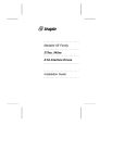
1
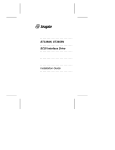
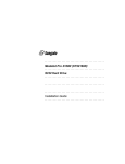
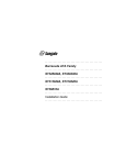
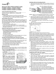
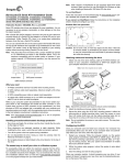
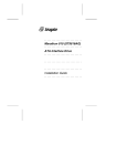
......................... ST5660A ......................... AT Interface Drive ......................... ......................... ......................... Installation Guide ......................... Contents Read before you begin... . . . . Configuring the drive . . . . . . Attaching cables . . . . . . . . Configuring the computer . . . . Low-level formatting . . . . . . Partitioning . . . . . . . . . . . High-level formatting . . . . . . Troubleshooting . . . . . . . . . Technical support services . . . Storing and shipping your drive . . . . . . . . . . . . . . . . . . . . . . . . . . . . . . . . . . . . . . . . . . . . . . . . . . . . . . . . . . . . . . . . . . . . . . . . . . . . . . . . . . . . . . . . . . . . . . . . . . . . . . . . . . . . . . . . . . . . . . . . . . . . . . . . . . . . . . . . . . . . . . . . . . . . . . . 1 3 5 9 10 10 11 11 16 19 © 1994 Seagate Technology, Inc. All rights reserved Publication Number: 36265-001, Rev. B June 1994 Seagate® , Seagate Technology® and the Seagate logo are registered trademarks of Seagate Technology, Inc. SeaFAX, SeaFONE, SeaBOARD and SeaTDD are trademarks of Seagate Technology, Inc. Other product names are registered trademarks or trademarks of their owners. Seagate reserves the right to change, without notice, product offerings or specifications. No part of this publication may be reproduced in any form without written permission from Seagate Technology, Inc. ST5660A Installation Guide, Rev. B 1 Read before you begin... Application. This Seagate® drive is designed for IBM AT and compatible personal computers. It uses the ATA interface. Warning. Turn off your computer before you open the case, touch any internal components or install the drive. Static discharge. Observe these precautions to avoid static electricity, which can damage a drive or a computer. Static electricity can be created by wool or synthetic clothing, carpets and plastics of any kind, including most bags. • Keep the drive in its static-shielded bag until you are ready to install it. Do not attach any cables to the drive while it is in its static-shielded bag. • Before you handle the drive, put on a grounded wrist strap, or ground yourself frequently by touching the metal chassis of a computer plugged into a grounded outlet. Wear a grounded wrist strap throughout the installation procedure. • Handle the drive gently and only by its edges or frame. Until you are ready to install it, place it only on an antistatic surface. • Do not touch the drive’s connector pins or its printed circuit board. Drive handling. The drive is extremely fragile—handle it with care. Do not attach labels to any part of the drive. Inspection. After you are familiar with the handling precautions listed above, inspect the drive. If it appears to be damaged, call your distributor or dealer immediately. Warranty. See your authorized Seagate distributor or dealer. 2 ST5660A Installation Guide, Rev. B Maintenance and repair. Seagate drives do not require maintenance. The head/disc assembly is sealed; a broken seal voids the warranty. Seagate customer service centers are the only facilities authorized to repair Seagate drives. Seagate does not sanction any third-party repair facilities. Radio and television interference. This product complies with Class B limits for radio noise emissions from computer equipment as set out in the radio interference regulations of the Canadian Department of Communications. Le présent appareil numérique n′émet pas de bruits radioélectriques depassant les limites applicable aux appareils numériques de Classe B prescrites dans le règlement sur le brouillage radioélectrique edicté par le Ministère des Communications du Canada. Sicherheitsanleitung 1. Das Gerrät ist ein Einbaugerät, das für eine maximale Umegebungstemperatur von 55°C vorgesehen ist. 2. Zur Befestigung des Laufwerks werden 4 Schrauben 6-32 UNC-2A benötigt. Bei seitlicher Befestigung darf die maximale Länge der Schrauben im Chassis nicht mehr als 5,08 mm und bei Befestigung an der Unterseite nicht mehr als 5,08 mm betragen. 3. Als Versorgungsspannugen werden benötigt: +5V ± 5% 0,65A +12V ± 5% 0,45A (1,9A fur ca. 10 Sek. fur ± 10%) 4. Die Versorgungsspannung muβ SELV entsprechen. 5. Alle Arbeiten dürfen nur von ausgebildetem Servicepersonal durchgeführt werden. 6. Der Einbau des Drives muβ den Anforderungen gemäβ DIN IEC 950V DC 0805/05.90 entsprechen. ST5660A Installation Guide, Rev. B 3 Configuring the drive 1. Turn the computer off. 2. Remove your computer’s outer case. Caution. Special training or tools may be needed to service portable computers. Removing the cover may void your warranty. Review the terms and conditions of your warranty before removing the cover. 3. Ground yourself. Wear a grounded wrist strap throughout this procedure, or frequently touch the metal chassis of a computer that is plugged into a grounded outlet. 4. Remove the drive from its antistatic bag. 5. Install master/slave jumpers. The options jumper block J8, shown in Figure 1 on page 4, accepts 2-mm connectors and jumpers. Use Seagate part number 13211-001 or equivalent. One-drive system: Configure the drive for a one-drive system as shown in Figure 1. Two-drive system: Do not use an ATA interface drive in a system with another drive having a controller that does not use the ATA interface. With two ATA interface drives, you must designate one drive as the master, or drive 0, and the other as the slave, or drive 1. This can be done in either of two ways: • When using cable select, if your computer and both drives support cable select and you want to use this option, first install three cable-select jumpers on pins 1 through 6 of J8 as shown in Figure 1; then use a special cable as described in step 5 of “Attaching cables” on page 5 to designate master and slave drives. 4 ST5660A Installation Guide, Rev. B J8. Options jumper block Circuit board 33 31 29 27 25 23 21 19 17 15 13 11 9 7 5 3 1 34 32 30 28 26 24 22 20 18 16 14 12 10 8 6 4 2 Spares One drive only Note. All other pins are reserved. Do not use them. Drive is master; slave is present Drive is slave Cable select (Reserved) (Reserved) Remote LED connection 1,024 cylinder option J8 pin 1 J1 pin 1 Figure 1. ST5660A Jumpers ST5660A Installation Guide, Rev. B 5 • If you are not using cable select and instead are using a standard ATA interface cable, configure the drive as a master or a slave as shown in Figure 1. Attaching cables Figure 2 on page 6 shows the locations of the drive connectors. 1. Make sure the computer is off. 2. Put on a grounded wrist strap. 3. Connect the remote LED (optional). If you want to connect the drive-activity indicating LED of your computer front panel to the drive, attach the two-wire LED connector cable from the case to pins 9 (–) and 10 (+) of jumper block J8 (shown in Figure 1). 4. Attach the power cable. Connect a system power cable to the 4-pin power connector. 5. Attach the interface cable. Note that the cable length must be 18 inches or less. Caution. Connector misalignment can damage the computer and the drive. One-drive system using standard ATA 40-pin interface cable: Connect one end of the cable to the computer’s host adapter card or the hard drive connector located on the motherboard, and the other end to interface connector J1 on the drive. Align pin 1 on each cable connector with pin 1 on its matching equipment connector. (Typically, an edge-stripe on the cable denotes cable lead 1 going to pin 1). Pin 1 of J1 on the drive is identified in Figure 2. 6 ST5660A Installation Guide, Rev. B J8 pin 1 J1 pin 1 J1. Interface connector J3. Standard power connector 1 2 3 4 Circuit board +5V +5V return +12V return +12V Figure 2. ST5660A Connectors ST5660A Installation Guide, Rev. B 7 Two-drive system with standard ATA 40-pin interface cable: If you are using a standard 40-pin two-drive ribbon cable, plug one connector into J1 on each drive and attach the remaining connector to the host adapter. Align pin 1 on connectors as described above for a one-drive system. Two-drive system using cable select: Use of this method requires drives supporting the cable select option and also requires a special daisy-chain interface cable built for cable-select; this cable is not the same as a standard 40 pin hard drive cable. To make a drive the master, attach it to the connector that has the CSEL signal line connected to pin 28. To make a drive the slave, attach it to the connector that has pin 28 unconnected. Finally, connect the cable to the host adapter. Note that CSEL is grounded on the host adapter. Mounting the drive Mount the drive securely in the computer, following recommended mounting orientations as shown in Figure 3 on page 8. When you position the drive, avoid crimping or stretching the drive cables. Caution. To prevent drive mounting hole damage, use only 6-32 UNC-2A mounting screws. Tighten them gently using less than 6 inch-pounds of torque. Bottom hole mounting method. Insert screws in all of the four bottom mounting holes as shown in Figure 3. Do not drive the screws more than 0.20 inches (6 turns) into the drive frame. Side hole mounting method. Insert screws in four of the six available side mounting holes as shown in Figure 3. Use two mounting holes on each side. Do not drive the screws more than 0.20 inches (6 turns) into the drive frame. 8 ST5660A Installation Guide, Rev. B Figure 3. Recommended mounting orientations ST5660A Installation Guide, Rev. B 9 Configuring the computer Configure your computer for the drive as follows: 1. Turn the computer on and follow the manufacturer’s instructiions for running the CMOS Setup routine. 2. When CMOS Setup starts, first select a drive type that matches your drive’s translation geometry: If none of the standard drive types offered by the Setup routine match the translation geometry shown in the following table, select the user-defined or custom drive type to enter your drive’s translation geometry. Translation geometry Sectors per Heads track Model ST5660A Mbytes (F)1 Cyl 543.762 1,0573 16 63 518.73 3 16 63 503.47 527.652 1,024 CMOS Mbytes 1. Mbytes reported by CHKDSK after a DOS format. 2. This capacity is supported by systems that allow more than 528 Mbytes per drive. 3. A jumper must be installed over pins 33 and 34 of jumper block J8. 10 ST5660A Installation Guide, Rev. B If your Setup routine does not offer a user-defined drive type, select a standard drive type with a capacity that most closely approximates, but does not exceed, your drive’s CMOS capacity (shown in the table’s last column). If you do not know what drive types your Setup routine supports, download the FindType utility from SeaBOARD (see page 18) to assist you in choosing an appropriate drive type. 4. The drive does not use the write precomp and landing zone parameters; entered values are ignored by the drive. For both parameters, enter as a value the number of cylinders plus 1. 5. Save into CMOS memory the changes you made and exit from the CMOS Setup routine. Low-level formatting AT drives are low-level formatted at the factory to 512 bytes per sector. You do not need to low-level format AT drives. Partitioning You must partition a drive into one or more logical drives before you can use it. If you are using DOS Version 3.3 or earlier, disc partitions are limited to approximately 32 Mbytes. Beginning with DOS Version 4.0, you can put the entire drive on one partition. Partitioning is described in your DOS manual. Caution. Partitioning or formatting a drive at any level erases all data on it. Before you repartition or reformat your drive, save all existing files to backup files. Seagate assumes no liability if you erase your data. ST5660A Installation Guide, Rev. B 11 High-level formatting High-level formatting verifies the information written by the lowlevel format and builds the file allocation table (FAT) used by DOS to access files on the drive. Consult your MS-DOS manual to learn how to use the DOS FORMAT utility to high-level format the drive. In Unix, high-level formatting creates the i-node used for file access information. Drive formatting and partitioning are both performed by a single operating system utility. Refer to your Unix operating system documentation for instructions. Troubleshooting In the event of problems, you should perform the following basic checks, which can resolve common installation difficulties. Warning. Always turn your computer off before changing jumpers or unplugging cables and cards. • Verify compatibility. Verify that the host adapter and the drive are appropriately matched to each other and to your computer. Refer to relevant documentation for details. • Verify equipment configuration. Using the instructions in the drive and host adapter installation guides, make sure that all appropriate jumpers are installed, or removed, as needed. • Check the power supply specifications. If new devices are installed, your computer’s power supply may not support new total power requirements. When in doubt, consult your dealer. • Check all cards. Verify that all cards are seated in their slots on the motherboard and are secured with mounting screws. 12 ST5660A Installation Guide, Rev. B • Verify the CMOS drive type setting. The drive type setting stored in CMOS memory using CMOS Setup must approximate, but not exceed, the physical specifications of your drive. • Check all cables. Make sure all ribbon cables are securely connected. Verify that they are not crimped or damaged, and if in doubt, substitute cables that are new or known to be good. Verify for each cable that cable connector pin 1 aligns with equipment connector pin 1. Pin 1 is often denoted by a colored stripe on one edge of the ribbon cable. Caution. Do not reverse-plug connectors. This can damage the computer and the drive. Note. A floppy diskette cable contains a split and twisted section and cannot be used with a hard drive. • Check for viruses. Before you use someone else’s diskette in your system for the first time, scan the diskette for viruses. If the preceding basic checks have been done and the problem still is not solved, follow these guidelines for troubleshooting: The system does not recognize the presence of the drive. • Check all cables. • Make sure the power supply is adequate to system needs. • Reboot the computer and make sure the drive motor runs. (If your drive is very quiet, it may be difficult to hear it come to operating rotational speed.) If the drive does not appear to be running, check all drive cables. • Verify the CMOS Setup drive type values. • Try a warm boot (a reboot without turning off computer power). To do this, press CTRL, ALT, and DELETE at the same time. ST5660A Installation Guide, Rev. B 13 If a warm boot causes a previously unrecognized drive to become recognized, there may be a timing problem in which the drive fails to become ready before the computer’s poweron self-test is complete. One possible solution is to slow your computer’s processor speed during startup. If your computer has a turbo switch, set it to slow speed before turning the computer on. If there is no turbo switch, you may be able to use keyboard commands to slow the processor speed; see your computer manual for details. After the computer is up and running, return the processor to the fast speed. Another solution is to warm-boot your computer after every power-on. • Check for I/O address conflicts. To isolate the conflict, first verify that the drive and host adapter are compatible with your computer by removing all peripheral adapter cards, except the video card; then reinstall the drive and host adapter card. If this is successful, reinstall the peripheral cards one at a time until the conflict reoccurs. After you have isolated the source of the address conflicts, you can resolve the conflict by changing the I/O address of the peripheral that appears to cause the conflict. The dealer partitioned and high-level formatted the drive for you in the store. Later, you installed the drive and it does not work at all. • Reboot the computer and make sure the drive spins up. • Check all cables. • Make sure the power supply is adequate to system needs. 14 ST5660A Installation Guide, Rev. B • Use the same version of DOS within all partitions. Make sure that the DOS version the dealer used to partition and high-level format the drive is the same as the version you have installed on your computer. If it isn’t, see your dealer. • Verify the CMOS drive type setup value. You must install the drive using the same drive type or translation geometry that was set before initial partitioning by your computer dealer. • Check for I/O address conflicts between peripheral cards. • Check for viruses. The screen goes blank when you power up the system. • Make sure the monitor is plugged in and turned on. • Check all cards. Make sure the video card is seated in its slot and secured with a mounting screw. • Check all cables. Make sure the video-card cables are securely attached. • While the computer is powered down, remove the drive host adapter. If the screen turns on after you reboot, the host adapter may be incompatible or defective. If so, see your dealer. The system hangs in FDISK or fails to create or save the partition record. • Check all cables. • The DOS utilities diskette may be corrupted. Try your backup DOS diskette. • Make the partitions smaller. ST5660A Installation Guide, Rev. B 15 • Use another drive type or translation geometry. Sometimes the computer’s BIOS does not accept a particular translation geometry value for writing into the CMOS Setup memory. • Change the interrupt jumper setting on the host adapter. • Check for media defects at the beginning of the drive. Use a third-party surface scan utility. The FDISK error message, “No Fixed Disk Present,” appears. • Check all cables. • Make sure the power supply is adequate to system needs. • Reboot the computer and make sure the drive spins up. • Verify the CMOS setup drive-type setting. • Check for I/O address conflicts. DOS messages, “Disk Boot Failure,” “Non-System Disk,” or “No ROM Basic - SYSTEM HALTED,” appear. • Check all cables. • Use the same version of DOS throughout all partitions. • Reinstall the DOS system files using the DOS SYS utility. • Use FDISK to verify that the primary partition is active. • Check for viruses. System error message, “Drive not Ready,” appears. • Check all cables. For each drive ribbon cable, verify that cable pin 1 is aligned with drive or host pin 1. Pin 1 is usually denoted by a stripe on the side of the ribbon cable. • Make sure the power supply is adequate to system needs. • Reboot the computer and make sure the drive spins up. 16 ST5660A Installation Guide, Rev. B During the DOS high-level format, the drive does not format to full capacity. • Verify your computer’s CMOS drive type setting. One of these problems may have occurred: 1) CMOS Setup may be set for an incorrect drive type or translation geometry; 2) you may have entered a parameter value that exceeded the physical capacity of the drive; or 3) you selected a CMOS geometry or drive type that does not take full advantage of the drive’s capacity. If any of these cases is true, follow the instructions on page 7 for configuring the computer. If you reset the CMOS drive type, partition and high-level format the drive again. Note that DOS does not allow more than 1,024 cylinders. • If you partitioned the drive into individual logical drives, you may need to make the partitions smaller so that the computer can use all of the drive’s capacity. Technical support services Always consult your computer dealer first for technical support. Dealers can offer help with unique system configurations. Technical support is available for all Seagate products by calling the SeaFAX, Seagate Technical Support FAX, SeaFONE, SeaBOARD and SeaTDD services. ST5660A Installation Guide, Rev. B 17 SeaFAX. 408/438-2620 You can use a touch-tone telephone to access Seagate’s automated FAX system to receive technical support information by return FAX. This service is available 24 hours daily. Location Telephone number United States 408-438-2620 England 44-62-847-7080 Seagate Technical Support FAX. 408/438-8137 You can FAX questions or comments to technical support specialists 24 hours daily. Responses are sent between 8:00 A.M. and 5:00 P.M. (Pacific time), Monday through Friday. SeaFONE. 408/438-8222 You can talk to a technical support specialist between 8:00 A.M. and 5:00 P.M. (Pacific time), Monday through Friday. SeaFONE provides recorded technical information on selected Seagate products while you are on hold. You can access the recordings 24 hours daily. Before calling, note your system configuration and drive model number (STxxxx). SeaTDD. 408/438-5382 Using a telecommunications device for the deaf (TDD), you can send questions or comments 24 hours daily and exchange messages with a technical support specialist between 8:00 A.M. and 5:00 P.M. (Pacific time), Monday through Friday. 18 ST5660A Installation Guide, Rev. B SeaBOARD Using a modem, you can: • Access documentation, drive specifications and jumper settings for Seagate’s entire product line. • Download software for installing and analyzing your drive. • Request a return phone call from the technical support staff. SeaBOARD is available 24 hours daily. It supports communications up to 9,600 baud. Set your communications software to eight data bits, no parity, and one stop bit (8-N-1). SeaBOARD phone numbers are listed below. Location Modem number United States 408-438-8771 Canada 416-856-5581 England 44-62-847-8011 France 33-1 40 67 10 34 Germany 49-89-140-9331 Singapore 65-292-6973 Australia 61-2-756-2359 Korea 82-2-556-7294 ST5660A Installation Guide, Rev. B 19 Storing and shipping your drive Keep your original box and packing materials for storing or shipping your drive. The box has a Seagate Approved Package label. Shipping a drive in an unapproved container voids the warranty. Call your authorized Seagate distributor to purchase additional boxes. Figure 4 shows how to pack a drive in an approved single-pack box. Please use the original packing materials as shown. Foam Antistatic bag Drive Foam Figure 4. A drive in an approved package Seagate Technology, Inc. 920 Disc Drive, Scotts Valley, CA 95066, USA Publication Number: 36265-001, Rev. B, Printed in USA