1
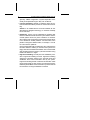
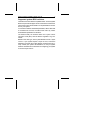
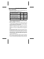
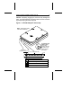
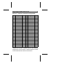
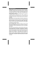
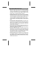
.......................... ST9144 Family: .......................... ST9051A, ST9052A, .......................... ST9077A, ST9096A, ......................... ST9144A .......................... Installation Guide .......................... Contents Read Before You Begin . . . . . . . . . . . . . . . . . . 1 Technical support service . . . . . . . . . . . . . . . . . . 2 Installation overview . . . . . . . . . . . . . . . . . . . . . 3 ST9144 family drives . . . . . . . . . . . . . . . . . . . . . 5 AT interface setup . . . . . . . . . . . . . . . . . . . . . . 5 Power management mode descriptions . . . . . . . . . . . 12 Drive mounting . . . . . . . . . . . . . . . . . . . . . . . . 15 Installation trouble-shooting . . . . . . . . . . . . . . . . . 16 © 1992 Seagate Technology, Inc. All rights reserved Publication Number: 36182-001, Rev. B Seagate®, Seagate Technology®, and the Seagate logo are registered trademarks of Seagate Technology, Inc. SeaFAX, SeaFONE, SeaBoard, and SeaCache are trademarks of Seagate Technology, Inc. Other product names are registered trademarks or trademarks of their owners. Seagate reserves the right to change, without notice, product offerings or specifications. No part of this publication may be reproduced in any form without written permission of Seagate Technology, Inc. ST9144 Family Installation Guide, Rev. B 1 Read before you begin... Verify that system power is off before attempting any installation. Observe static discharge precautions. Keep the drive in its static-shielded bag until you are ready to complete the installation. • Do not touch the circuit board or the I/O connector pins. • Always handle the drive by the edge or frame. Never apply pressure to the circuit board or to the drive top cover. Use a grounded wrist strap at your workstation; if unavailable, ground yourself frequently by touching the metal chassis of the system before handling any components. Provide antistatic padding on all work surfaces. Avoid static-inducing carpeted areas. Check all items. Examine the drive, cables, mounting hardware and accessories, documentation, and packaging. If any item is incorrect, missing or appears damaged, contact your distributor or dealer immediately. Important handling note. Improper handling during transit or shipping accounts for many installation problems. Always handle the drive carefully. Do not attach any labels to the drive top cover, as they may prevent proper heat dissipation from the unit. Warranty. Contact your authorized Seagate distributor or dealer for warranty information. Maintenance and repair. Seagate drives do not require any preventive maintenance. The head/disc assembly is sealed and does not contain any user-serviceable components. Tampering with the factory seal voids the warranty. Seagate customer service centers are the only facilities authorized to service Seagate drives. Seagate does not sanction any third-party repair facilities. 2 ST9144 Family Installation Guide, Rev. B Shipping. When transporting or shipping a drive, you must use a Seagate-approved container. Keep your original box. They are easily identified by the Seagate Approved Package label. Shipping a drive in a non-approved container voids the drive warranty. Seagate service centers may refuse receipt of components improperly packaged or obviously damaged in transit. Call your authorized Seagate distributor to purchase additional boxes. Seagate recommends shipping by an air-ride carrier experienced in handling computer equipment. Technical support services Product technical support is available for all Seagate products by calling the SeaFAX, SeaFONE, and SeaBOARD services. These are toll calls. SeaFAX: 408/438-2620 You can use a Touch-Tone telephone to access Seagate’s automated FAX system and select technical support information by return FAX. This service is available 24 hours a day, 7 days a week. SeaFONE: 408/438-8222 The enhanced phone system provides recorded technical information on selected Seagate products while you are on hold. Technical support specialists are available to answer questions from 8:00 AM to 5:00 PM PST, Monday through Friday. Recordings are accessible 24 hours a day, 7 days a week. SeaBOARD: The Seagate Technical Support Bulletin Board System (BBS) is available 24 hours a day, 7 days a week. A modem is required to access this service. Set your communications software for eight data bits, no parity and one stop bit (8N1). ST9144 Family Installation Guide, Rev. B 3 With this service you can access: • Specifications and configuration for Seagate products. • Reprints of Seagate documentation. • A directory of information and helpful utilities that you can download to your own computer. • The FINDTYPE.EXE utility is designed to make drive installation easier. It compares the drive’s geometry with all geometries supported by the system BIOS. FINDTYPE either signals if an exact match exists between the drive geometry and the system BIOS, or recommends the closest drive type supported by your system BIOS. BBS Location Modem Number Maximum Baud Rate United States 408-438-8771 9600 England 44-62-847-8011 9600 Germany 49-89-140-9331 2400 Singapore 65-292-6973 9600 Australia 61-2-756-2359 9600 Installation overview Installation of the drive can be divided into distinct phases as outlined below. Some of these may not be applicable to your particular installation requirements. Refer to the drive installation section for specific information on your drive model. • CMOS configuration (for AT systems only). Basic information about the drive must be entered into the host system CMOS so that it may properly access the drive for reading and writing data. The number of heads, cylinders, and sectors per track are specific to each drive and collectively define the drive 4 ST9144 Family Installation Guide, Rev. B geometry. CMOS configuration is system-dependent and is usually accomplished through a utility such as SETUP. • Low-level formatting. Seagate AT interface drives are lowlevel formatted at the factory and do not need low-level formatting. Caution. If an installed drive is low-level formatted, all user data will be lost. Seagate Technology, Inc. assumes no liability for lost user data. • Partitioning. A drive can be subdivided into partitions that behave as individual drives within the system. Earlier versions of DOS (before version 4.0) have a limitation on maximum drive capacity and consequently require higher capacity drives to be divided into smaller partitions. For DOS users, each partition is assigned a different letter, for example, C: and D: for a drive with two partitions. Use the DOS FDISK utility to partition the drive. After the drive has been defined in CMOS, you must boot the system to the floppy drive with a bootable DOS diskette. Then run the FDISK utility to partition the drive. Refer to your DOS manual for using FDISK. Use DOS 3.3 or higher. • High-level formatting. The last part of the installation procedure is high-level formatting the drive. High-level formatting verifies the information written by the low-level format and establishes drive access information used by the system. High-level formatting in DOS creates the File Allocation Table (FAT) used by DOS for drive access. The high-level format is initiated by the FORMAT command. Refer to your DOS manual for instructions on using the FORMAT command. ST9144 Family Installation Guide, Rev. B 5 ST9144 family AT interface drives This guide provides installation information for the ST9051A, ST9052A, ST9077A, ST9096A, and ST9144A drives. All drives in this family automatically park their heads at power-down. Refer to Figure 1. Caution. These drives are usually installed in notebook or laptop systems. These computers require qualified or factory trained technicians to perform peripheral upgrades. Be sure to review the terms and conditions of your system warranty before opening the system enclosure. Default drive geometry Seagate AT interface drives mimic (translate) other drive geometries. If none of the drive types offered by the CMOS support the number of heads, cylinders and sectors per track shown by the following table, and your system does not support a “user-defined” drive type, then select a drive type in your system CMOS with a capacity which is less than or equal to the capacity given in the “CMOS MBytes” column of the following table. If you do not know which drive types your CMOS supports, download FINDTYPE.EXE to assist in choosing an appropriate drive type. Refer to the “Technical Support Services” section in the front of this guide. When specifying drive geometry to the system CMOS, different values may be used for the Cylinders (1,024 max), Read/Write Heads (16 max), and Sectors per Track (63 max). 6 ST9144 Family Installation Guide, Rev. B Note that the final drive capacity shown by the CMOS and total sectors cannot exceed the values indicated in the last column of the following table as defined by the following equation: (Sectors)×(Heads)×(Cylinders) ≤ Total Sectors per Drive If your BIOS offers a “custom drive” or a “user-defined” drive type, you may use one of the configurations listed below. Model MBytes CMOS R/W Sect./ Cyl. (F) MBytes (F) Heads Track Total Sect. / Drive ST9051A 42.86 40.87 654 4 32 83,712 ST9051A 42.82 40.84 820 6 17 83,640 ST9052A 42.65 40.67 980 5 17 83,300 ST9077A 64.05 61.09 802 4 39 125,112 ST9096A 85.29 81.34 980 10 17 166,600 ST9144A 127.94 122.02 980 15 17 249,900 The CMOS calculation of drive capacity is based on a variation of the number of bits in a megabyte, for purposes related to drive addressing. When the drive geometry has been entered into the “user-defined” or “custom” drive type, the CMOS may display the calculated drive capacity. This number should correspond with the capacity listed in the “CMOS MBytes (F)” column of the table. Note that the drive provides the user with full capacity as specified in the “Mbytes (F)” column of the table. After the high-level formatting has been completed, the drive capacity can be verified using the DOS CHKDSK utility. ST9144 Family Installation Guide, Rev. B 7 Supported system BIOS revisions These drives are AT interface compatible drives. The host system BIOS must provide full support for the AT interface command set. Consult the system documentation for implementation information for your system. In accordance with the ATA/CAM specification, after a hard reset is received from the host, the BIOS must reset any emulation/translation parameters for the drive. The ST9144 family AT interface drives use 4 bytes of Error Correction Code (ECC) with the Read Long/Write Long commands. Based on the drive type, some system BIOSes look for 7 bytes of ECC. If your system expects 7 bytes of ECC, some drive diagnostic programs return false failures (typically time-out errors). Consult your system documentation, or call your system dealer or manufacturer for information on configuring your system to receive 4 bytes of ECC. 8 ST9144 Family Installation Guide, Rev. B Drive configuration • Master/Slave configuration. Refer to the table below to configure up to two drives on a single AT bus. System Configuration Pins A-B Pins C-D Drive is Master, no Slave present Removed Removed Drive is Master, Seagate Slave present* Removed Installed Drive is Slave to another ST9144 Family AT Drive Installed Removed Reserved Positions (Do Not Use) Installed Installed *Includes ST125A, ST138A, ST157A, ST1102A, ST1144A, ST351A, ST3096A, ST3120A, ST3144A, ST9051A, ST9052A, ST9077A, ST9096A, and ST9144A. • Power connection. The ST91 44 family driv es u se +5 Volts DC power supplied to the drive through the interface connector. Refer to the “44-Pin AT Interface Connector Assignment” table for specific pin assignments. Caution. The drive does not use +12 Volts DC power. Make sure only +5 Volts DC is being supplied to the drive, as specified in the “44-Pin AT Interface Connector Assignment” table. • Attach AT interface cable. Use a 44-pin AT interface connector cable with two rows of 22 female contacts on 0.079 inch (2 mm) centers. Pin 20 has been removed on the connector for keying purposes. A dual-drive system requires a 44-pin AT interface daisy-chain cable. Most cables have a stripe down one side to designate Pin 1. Make sure Pin 1 on the interface cable connector is aligned to Pin 1 on the drive interface connector and Pin 1 on the host connector. The maximum cable length is 18 inches (457 mm). ST9144 Family Installation Guide, Rev. B 9 Caution. Improperly plugging the connector may damage the drive. To prevent damage, the mating cable connector should be keyed by blocking the hole for Pin-20. Figure 1: ST9144 family AT drive setup Note: The drive is shown with the PC Board up. Notch Master/Slave Configuration Jumpers Pin 1 For ST9051A and ST9077A Only: A notch here indicates the drive has metric screw threads, thread size: M3x0.5 Key - Pin 20 (Removed) PCB A B C D Drive is Master, no Slave drive present Drive is Master, Seagate Slave drive present Drive is Slave to another ST9144 Family Master Reserved Positions (Do Not Use) 10 ST9144 Family Installation Guide, Rev. B Drive Formatting Seagate AT Interface drives are low-level formatted at the factory and do not need low-level formatting. Drive partitioning should be done using the DOS FDISK utility. Use DOS 3.3 or higher. If you are partitioning the boot drive, make sure that the primary DOS partition is marked active. Caution. If the drive was previously in use, make sure all data has been safely backed-up from the drive. Formatting or partitioning at any level may result in a partial or complete loss of user data. Seagate Technology assumes no liability for lost data. If the drive is to be made bootable be certain that the system files are copied onto the drive. Consult your DOS manual for FORMAT and FDISK command options and syntax. ST9144 Family Installation Guide, Rev. B 11 44-Pin AT interface connector assignments Pin 01 03 05 07 09 11 13 15 17 19 21 23 25 27 29 31 33 35 37 39 41 43 Signal I/O /Host Reset O Host Data 7 I/O Host Data 6 I/O Host Data 5 I/O Host Data 4 I/O Host Data 3 I/O Host Data 2 I/O Host Data 1 I/O Host Data 0 I/O Ground Reserved /HIOW O /HIOR O Reserved Reserved IRQ 14 I Host ADDR 1 O Host ADDR 0 O /Host CS0 O /DASP Notes +5 VDC (Logic) Ground Pin 02 04 06 08 10 12 14 16 18 20 22 24 26 28 30 32 34 36 38 40 42 44 Signal I/O Ground Host Data 8 I/O Host Data 9 I/O Host Data 10 I/O Host Data 11 I/O Host Data 12 I/O Host Data 13 I/O Host Data 14 I/O Host Data 15 I/O Key No Pin Ground Ground Ground Reserved Ground /Host IO16 (AT) I /PDIAG (16) Notes Host ADDR 2 O /Host CS1 O Ground +5 VDC (Motor) Reserved / indicates active low signal. Direction is with respect to the host. I indicates to the host, O indicates from the host. Reserved pins/ground do not have direction. /PDIAG and /DASP are used for communication between master and slave drives. 12 ST9144 Family Installation Guide, Rev. B Power management mode descriptions The ST9144 family drives feature four-phase power management with Active, Idle, Standby and Sleep modes. Power management is required for low-power portable systems, and is enabled through a system-dependent set-up procedure. Consult your system documentation for power management information. ST9051A power management mode descriptions Active mode. The drive is in Active mode during the read/write and seek operations. Idle mode. At power-on the drive defaults to Idle mode after 5 seconds of inactivity. The spindle is up to speed. The heads are parked and latched away from the data zones for maximum data integrity. The drive is Ready and accepts all commands. Standby mode. The drive enters Standby mode when a Standby Immediate command is received from the host. The drive also enters Standby mode after a specifiable length of time has elapsed with the drive in Idle mode. The Standby timer is systemdependent, and is usually established by the user with a system utility such as Setup. In Standby mode, the SeaCache buffer remains enabled, the heads are parked and the spindle is at rest. The drive accepts all commands, and returns to Active mode when disc access is necessary. Sleep mode. The drive enters Sleep mode when a Sleep Immediate command is received from the host. The heads are parked and the spindle is at rest. The drive leaves Sleep mode when a hard or soft reset is sent from the host. After a soft reset is received, the drive exits Sleep mode with all current emulation/translation parameters intact. ST9144 Family Installation Guide, Rev. B 13 Idle and standby timers. Default time delays for both the Idle timer and the Standby timer are set by the drive at power-on. These delays can also be specified by the user via the system Setup utility. Each time the drive performs an Active function (read, write or seek) the Idle timer is re-initialized, and begins the countdown from the specified delay time to zero. If the Idle timer reaches zero before any drive activity is required, the drive transitions into Idle mode. Upon transitioning to Idle mode, the drive begins the Standby timer countdown. If the Standby timer reaches zero before any drive activity is required, the drive transitions into Standby mode. In both Idle and Standby mode the drive accepts all commands, and returns to Active mode when disc access is necessary. ST9052A, ST9077A, ST9096A, and ST9144A power management mode descriptions Active mode. The drive is in Active mode during the read/write and seek operations. Idle mode. At power-on the drive sets the Idle timer to enter Idle mode after 5 seconds of inactivity. The Idle timer delay can also be set by the user via the system Setup utility. In Idle mode the spindle remains up to speed. The heads are parked and latched away from the data zones for maximum data integrity. The drive accepts all commands, and returns to Active mode when disc access is necessary. 14 ST9144 Family Installation Guide, Rev. B Standby mode. The drive enters Standby mode when a Standby Immediate command is been received from the host. The drive can also enter Standby mode after a specifiable length of time has elapsed with the drive in Idle mode. The Standby timer is system-dependent, and is usually established by the user with a system utility such as Setup. In Standby mode, the SeaCache buffer remains enabled, the heads are parked and the spindle is at rest. The drive accepts all commands, and returns to Active mode when disc access is necessary. Sleep mode. The drive enters Sleep mode when a Sleep Immediate command is received from the host. The heads are parked and the spindle is at rest. The drive leaves Sleep mode when a hard or soft reset is sent from the host. After a soft reset is received, the drive exits Sleep mode with all current emulation/translation parameters intact. Idle and standby timers. Default time delays for both the Idle timer and the Standby timer are set by the drive at power-on. These delays can also be specified by the user via the system Setup utility. Each time the drive performs an Active function (read, write or seek) the Idle timer is re-initialized, and begins the countdown from the specified delay time to zero. If the Idle timer reaches zero before any drive activity is required, the drive transitions into Idle mode. Upon transitioning to Idle mode, the drive begins the Standby timer countdown. If the Standby timer reaches zero before any drive activity is required, the drive transitions into Standby mode. In both Idle and Standby mode the drive accepts all commands, and returns to Active mode when disc access is necessary. ST9144 Family Installation Guide, Rev. B 15 Drive mounting The drive can be mounted in any of the approved orientations shown in Figure 2. A minimum clearance of 0.030 inches (0.762 mm) should be allowed around the entire perimeter of the drive to allow for cooling airflow. Note. These mounting orientation recommendations do not apply to the ST9052A, which may be mounted in any orientation. Figure 2: Approved mounting orientations ACCEPTABLE NOT RECOMMENDED 16 ST9144 Family Installation Guide, Rev. B Mounting specifications The ST9144 family drives are built with metric mounting screw threads. Screw insertion depth is limited to 0.150 inches (3.81 mm) maximum on the side mounting holes and 0.190 inches (4.82 mm) maximum on the bottom mounting holes. The screw size for the bottom and the side mounting holes is M3X0.5. Caution. Do not exceed 3 inch-lbs torque for mounting screws. ST9051A only. ST9051A drive with part number 914003-XXX has standard screw thread size: 4-40 UNC-2B. ST9052A only. Screw insertion depth on the ST9052A is limited to 0.1490 inches (3.80 mm) maximum on the side and bottom mounting holes. Installation trouble-shooting Before you begin trouble-shooting, read and be aware of all the considerations discussed in this section. The suggestions presented here resolve the vast majority of installation problems. Warning. Always power down the system before changing jumper settings or unplugging cables and cards. • Verify compatibility. Check the documentation for the host adapter and the drive to confirm that these components are appropriately matched for each other and to your system. • Verify your configuration. Refer to the drive and controller installation guides to make sure all jumper settings suit your configuration requirements. • Check all cables. Make sure all cables are securely connected. Ribbon cables are especially fragile. Make sure they are not crimped or damaged in any way. Having extra cables on hand for trouble-shooting saves time and frustration. ST9144 Family Installation Guide, Rev. B 17 Note. Most cables have a stripe down one side to designate the Pin 1 location. Make sure Pin 1 on the interface cable connector is connected to Pin 1 on the drive interface connector and Pin 1 on the host connector. Refer to Figure 1 for the location of Pin 1 on the drive interface connector. • Check all cards. Make sure all cards are securely seated in the expansion slots on the motherboard. Full size (16-bit) cards cannot be plugged into half-size (8-bit) slots. Make sure all cards are plugged into appropriately sized expansion slots. Once the cards are permanently installed, and the system is running properly, use mounting screws to secure them in place. • Check the power supply specifications. The output of your power supply may not meet the power requirements of the new devices you are installing. If you are not sure whether the power supply meets the system requirements, consult your system dealer or distributor. • Use the same version of DOS throughout your system. The same version of DOS must be used throughout all phases of building and configuring your system. • Verify the CMOS drive type. The CMOS drive type must approximate, but not exceed, the physical specifications and maximum drive capacity of the disc drive. Refer to the Default Drive Geometry section of this installation guide for drive specifications and CMOS configuration information. • Check for viruses. Before installing any new software, scan the installation diskettes for viruses. After the software has been installed on the hard disc, scan that drive for viruses. Symptoms of viruses can include intermittent system lock-ups, re-boots, drive errors, etc. Notes Notes Notes Notes Notes Notes Notes Notes Seagate Technology, Inc. 920 Disc Drive, Scotts Valley, CA 95066-4544, USA Publication Number: 36182-001, Rev. B