1
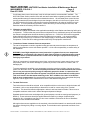
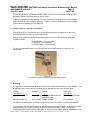
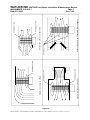
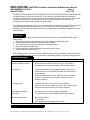
WATLOW IND. WATROD Duct Heater Installation & Maintenance Manual
I&M NUMBER: 316-42-6-1
Date:6/11/2008
Page: 1
Rev: 3.00
________________________________________________________________________________________________________________________________________________________________________________________________________________________
Pre Installation
•
•
•
Check to make sure that heater received is the same as that ordered.
Elements may come in contact with each other during shipment. Minor adjustments to elements may be
required prior to installation to separate them. Extensive bending of elements should be avoided since
dielectric strength between coil and sheath may be compromised.
Watlow heaters are built to comply with global dielectric requirements, it may be necessary due to
atmospheric conditions / humidity, to perform a dielectric test prior to startup. (Refer to Insulation
Resistance (megohm) precheck test under Installation section)
Safety
Electric heaters are inherently dangerous!! Care should be taken to read and completely understand the
Installation and Maintenance manual before installing and wiring the heater. Any installation and
maintenance performed on the heater shall be done by a qualified electrician, in accordance with the
governing and other electrical codes as they apply. It is the users responsibility to ensure that the heater
being used is properly selected and installed in the application.
!
The Caution Symbol (exclamation point) alerts you to a "CAUTION", a safety or
functional hazard which could affect your equipment or its performance.
The warning symbol (lightning bolt) alerts you to a "WARNING", a safety hazard which
could affect you and the equipment
Installation
Proper heater selection and installation will result in efficient heat transfer, safe operation, and long heater
life.
1. Insulation Resistance (Megohm) precheck
The insulation resistance was tested to the applicable standard(s) at the Watlow manufacturing facility
prior to shipement. During shipping and/or storage, moisture absorption by the insulation material within
the element is possible. The insulation resistance value is reflective of the product volume resistance.
The measured value in ohms at a given temperature can be used to estimate the current leakage when
a voltage is applied. The user should assure the the volume resistance is adequate to keep current
leakage at or below desired levels during startup and operation. Some products have ends seals that
allow water vapor to enter and exit the product. It is normal for the current leakage to change with time
and temperature on products with “breathable” end seals. The current leakage may be lower after the
product reaches equilibrium temperatures due to loss of water vapor from within the product. If the
insulation material is “dry” the volume resistance will decrease with temperature, and the current leakage
will increase with temperature. To test the volume resistance use a 500 VDC megohm meter (Megger)
and connect to any heater terminal and the heater sheath that is part of a load circuit. A suggested good
practice is to achieve a value of more than 10 megohms when the unit is at room temperature. The
actual required value depends on the allowed current leakage when voltage is applied to the product.
If several units are interconnected, the megohm of the heater is obtained by taking the reading and
dividing by the number of interconnected elements. This reading should be greater than 10 megohms.
If an undesirable megohm value exists, two alternative methods can be used to remedy the situation.
One method is to place the product in an oven and raise the entire product temperature to remove
moisture. Contact Watlow to determine what temperatures your product can safely be baked out to
avoid damage to components.
WATLOW IND.n # 6 INDUSTRIAL LOOP RD. n HANNIBAL MO, 63401n PHONE 573-221-2816 n FAX 573-221-3723
WATLOW IND. WATROD Duct Heater Installation & Maintenance Manual
I&M NUMBER: 316-42-6-1
Date:6/11/2008
Page: 2
Rev: 3.00
________________________________________________________________________________________________________________________________________________________________________________________________________________________
If solid state power control devices are used, the soft start mode is recommended if available. The
WATLOW Power Series controller offers soft start and heater bakeout operating modes to assure the
safest possible startup of heaters that have absorbed moisture. All solid state power control devices
must be protected with fuses designed to prevent damage to the device in the event of a short circuit.
For SCR protection I2t fusing is required and must be sized below the I2t rating of the SCR to insure
protection. If a fuse opens during operation, contact the factory to discuss why the fuse blew, and
determine what the necessary corrective action is.
2.
Dielectric strength (HiPot)
The dielectric strength was tested to the applicable standard(s) at the Watlow manufacturing facility prior
to shipement. To assure that the product was not subjected to any conditions that may have decreased
the dielectric strength below desired levels during shipment, etc. a 1000 VAC HiPot test is suggested.
Higher dielectric test values should be reviewed by Watlow prior to testing. It is recommended to
perform the HiPot test prior to connection of the voltage supply to avoid upstream damage to other
components. Follow the HiPot testing procedures issued by the equipment manufacturer.
3.
Protection of heater elements from over temperature
The use of temperature controls to regulate heating process and prevent heater over temperature is
highly recommended to ensure safe heater operation. It is the users responsibility to ensure safety of
the installation.
WARNING: Install high temperature control protection in systems where an over temperature
fault condition could present a fire hazard or other hazard. Failure to install temperature control
protection where a potential hazard exists could result in damage to equipment and property,
and injury to personnel.
Failure of components in a temperature control loop, such as the sensor, heater control relay or main
temperature control, can result in damage to a product in process, a melt down of a heater, and / or
damaging fire.
To protect against this possibility, over temperature protection must be provided to interrupt or remove
power from the heater circuit. A bulb and capillary thermostat is not recommended for this function
since it may not respond quickly enough to adequately protect the heater. In cases where the
thermostat bulb gets too hot before the system is turned off, the thermostat bulb could rupture.
This could result in the thermostat remaining in the "ON" condition since there is insufficient
fluid to move contacts apart. We recommend the temperature protection have appropriate third party
approval, and be applied in the classification for which it was tested and approved.
4. Terminal Enclosures
Terminal enclosures should be selected to be compatible with the environment in which the heater will
be located. It is the users responsibility to determine the need for correct rating of the Terminal
enclosure. This should be based on appropriate national and local electrical codes. Failure to use a
compatible enclosure could result in heater damage and personnel danger.
Standard terminal enclosures are designed for general purpose use and are rated general purpose ( ex
NEMA 1). These enclosures should be applied where there will be no danger of spilled liquids,
dampness, dirt, or hazardous gas, fibers or dust. eous conditions. Enclosures for wet or hazardous
locations are also available from Watlow.
Although enclosures are supplied over the terminals, units should be located in an area that will minimize
the chance of being hit by falling or moving objects. The terminals must be protected at all times from
moisture.
WATLOW IND.n # 6 INDUSTRIAL LOOP RD. n HANNIBAL MO, 63401n PHONE 573-221-2816 n FAX 573-221-3723
WATLOW IND. WATROD Duct Heater Installation & Maintenance Manual
I&M NUMBER: 316-42-6-1
Date:6/11/2008
Page: 3
Rev: 3.00
________________________________________________________________________________________________________________________________________________________________________________________________________________________
In hazardous locations, (as defined in NFPA 70 NEC, Article 501 or other similar standards global
standards) explosion resistant housings must be used.
In order to maintain termination integrity, the terminal enclosure should be kept below the maximum
temperature rating of the internal components. Insulation should not be added to the bare external
surfaces without consulting the manufacturers.
5. Torque Values for Terminal Connections
To prevent arcing it is important that all of the terminals connections be tightened, whether it the
individual element terminals or the connection blocks.
Watlow recommends the following torque specifications for the tin plated aluminum feeder wire
connection blocks:
For #4-#6 AWG – 45 inch/pounds
For #8 AWG – 40 inch/pounds
For #10-#14 AWG – 35 inch/pounds
The #10-32 threaded hex nuts on the individual element terminals need to be tightened to 20
inch/pounds.
Figure #1
Tin Plated Aluminum Connection Blocked with lead wire
6. Gasketing
It is important to completely seal off the process air flow from the terminal enclosure using a gasket. For
air applications we recommend the following gaskets depending on the process temperature.
Process
Temperature (°F)
Up to 370°C (700 °F)
Up to 500°C (932 °F)
Thickness
Material
1/8”(3.18 mm) Compressed Asbestos-Free
Fiber Reinforced
1/8”(3.18 mm) Flexible Graphite
ASTM F104
Line Call Out
F712100A9B4E22K5M6
F517100B1M3
For applications other than air or at higher temperatures consult the factory or a gasket manufacturer.
If the opening in the duct work is larger than the area required for the duct heater, the terminal area may
be exposed to air at temperatures which exceeds the terminal enclosures rating. Therefore, it is
recommended that gaps the duct and the heater be sealed off using tadpole gaskets that are rated to the
WATLOW IND.n # 6 INDUSTRIAL LOOP RD. n HANNIBAL MO, 63401n PHONE 573-221-2816 n FAX 573-221-3723
WATLOW IND. WATROD Duct Heater Installation & Maintenance Manual
I&M NUMBER: 316-42-6-1
Date:6/11/2008
Page: 4
Rev: 3.00
________________________________________________________________________________________________________________________________________________________________________________________________________________________
process temperature. This will help to lower the terminal enclosure temperature and save energy. See
Figure 2 for an example of how tadpole gaskets will seal off the terminal from being exposed to process
temperatures.
This surface of the insulation retainer should
be flush with the inside of the mating duct.
Projecting this surface beyond the inside duct
surfac will increse the pressure drop.
This surface of the tadpole gasket should
“seat out” on the insulation retainer surface
that is flush with the inside wall of the
ductwork
Figure # 2
Using Tadpole Gaskets to Seal off the Air Flow.
7. Lifting / Installing
Duct heaters can be lifted in the horizontal or vertical position as long as straps are used that are
suitable for the size and the weight of the heater. For horizontal lifting we recommend using two straps,
one supporting the bundle using the element supports and the other the terminal enclosure. The strap
for the element bundle should not be looped through the elements, only the support rods. This protects
the elements from possible damage from lifting. The second strap shoud support the terminal housing.
See Figure # 3 below for locations for straps.
Once the heater has been lifted and is being installed into the ductwork the strap in the bundle should be
removed only after the bundle has been placed inside of the ductwork. The strap on the housing should
be removed just prior to the heater being securely mounted into place.
For verical lifting a strap can be attached vertically around the terminal enclosure and the insulation
retainer. In order to do this the strap can be slipped through the space between the element bundle and
the insulation retainer. Avoid putting the strap through the elements to prevent possible damage from
lifting. See Figure #4 below for examples.
WATLOW IND.n # 6 INDUSTRIAL LOOP RD. n HANNIBAL MO, 63401n PHONE 573-221-2816 n FAX 573-221-3723
WATLOW IND. WATROD Duct Heater Installation & Maintenance Manual
I&M NUMBER: 316-42-6-1
Date:6/11/2008
Page: 5
Rev: 3.00
________________________________________________________________________________________________________________________________________________________________________________________________________________________
Figure #3
Install Lifting strap between element bundle and support bracket. Do entwin straps between elements.
Place second strap around terminal enclosure.
Figure #4
For Vertical lifing place strap through the space between the element bundle and the insulation retainer.
Do not slip the strap through the elements.
For other optional lifting procedures please consult the factory.
8. Orientation / Mounting
The duct heater may be mounted vertically, or horizontally, from the left to right, top or bottom. The inlet
side of the unit must be at least 48" (1.2m) downstream from any transition in duct size or direction, or
from any air handling equipment. See Figure 3 for locations that should be avoided.
WATLOW IND.n # 6 INDUSTRIAL LOOP RD. n HANNIBAL MO, 63401n PHONE 573-221-2816 n FAX 573-221-3723
WATLOW IND. WATROD Duct Heater Installation & Maintenance Manual
I&M NUMBER: 316-42-6-1
Date:6/11/2008
Page: 6
Rev: 3.00
________________________________________________________________________________________________________________________________________________________________________________________________________________________
Heaters may be ganged in parallel for nearly any total wattage desired. The temperature control
thermocouple if so equipped should be located near the outlet to sense exiting air temperature. It may
be desirable to use in inlet and outlet temperature sensor for cascade style control. Conduct process
temperature sensing in the outlet stream away from the heater.
Minimum air velocity through the heater is 200 fpm for air temperatures approaching 800°F (412°C).
Lower velocities will jeopardize element life.
Air flow over the entire face of the heater should be uniform throughout the cross section of the ductwork
before entering the heater bundle at the design velocity.
The units screw or bolt in place through the 3/8" (9.525 mm) dia. holes in the mounting flange. When
installed vertically through the top of the duct, they are self supporting when the duct is capable of
supporting the heater weight.
WATLOW IND.n # 6 INDUSTRIAL LOOP RD. n HANNIBAL MO, 63401n PHONE 573-221-2816 n FAX 573-221-3723
WATLOW IND. WATROD Duct Heater Installation & Maintenance Manual
I&M NUMBER: 316-42-6-1
Date:6/11/2008
Page: 7
Rev: 3.00
Figure # 5
WATLOW IND.n # 6 INDUSTRIAL LOOP RD. n HANNIBAL MO, 63401n PHONE 573-221-2816 n FAX 573-221-3723
Heater blocked by filter and filter support
Heater too close to blower
OVERHEATING
OVERHEATING
OVERHEATING
Heater too close to transition
Heater too close to elbow
OVERHEATING
OVERHEATING
OVERHEATING
________________________________________________________________________________________________________________________________________________________________________________________________________________________
WATLOW IND. WATROD Duct Heater Installation & Maintenance Manual
I&M NUMBER: 316-42-6-1
Date:6/11/2008
Page: 8
Rev: 3.00
________________________________________________________________________________________________________________________________________________________________________________________________________________________
When installed horizontally the user must determine whether the duct wall has sufficient strength to
support the unit by the flange only. A frame may be necessary to support the unit in the duct. This frame
can have tapped holes or captive nuts to receive mounting bolts. An access panel in the duct can
facilitate installation.
DANGER: HAZARD OF FIRE. Electric heaters are capable of developing high temperatures so extreme
care should be taken to locate heaters in safe environments. Mounting heaters in atmospheres
containing combustible gases and vapors should be avoided. According to article 501 of the NEC, the
maximum surface temperature of the heater shall not exceed 80 % of the auto-ignition of the surrounding
atmosphere when the heater is continuously energized. Care should also be taken to keep combustible
materials far enough away to be free of the effects of high temperatures.
9. Mounting Holes / Bolts
Standard mounting holes are 3/8” (9.53 mm) diameter with a tolerance of 0.005” (0.13 mm). The center
line to center line spacing on the mounting holes of the flange have a tolerance of 0.015” (.38 mm),
therefore the mounting holes on the duct should also have a center line to center line tolerance of 0.015”
(0.38 mm).
For duct heaters with Carbon Steel Flanges 5/16” – 16 UNC-2B Grade 5, SAE J429 (M8 x 1.25 x length
ASTM A449) bolts should be used. For 304 Stainless Steel Flanges 5/16” – 16 UNC-2B Grade B8,
ASTM A320 (M8 x 1.25 x length ASTM A320) bolts should be used. Recommended washers are 5/16”
(7.94 mm) spring type in the corresponding material. For other flange materials consult the factory. The
thread engagement on the bolts should be equal to or exceed the cross section diameter of the bolt.
It is important when tightening the bolts that enough torque is used to seat the gasket. A minimum
torque of 50 ft/lbs is recommended to seat a 1/8” (3.18 mm) thick gasket of the materials recommended
in Section 6.
Consult the factory for proper mounting bolt size if mounting hole size is not 3/8” (9.53 mm) diameter.
10. Wiring
WARNING; HAZARD OF ELECTRIC SHOCK. Any installation involving electric heaters must be
grounded to earth to eliminate shock hazard.
Electrical wiring to the heaters must be installed in accordance with the National Electric Code and any
state and local electrical code by qualified personnel.
Consult wiring diagram supplied with the unit for correct feeder wires connections. If one is not supplied,
the factory should be consulted for the appropriate wiring diagram. Feeder wire should be properly
selected based on amperage, electrical power rating, ambient temperature, and type of environment.
Feeder wire should also be housed in either rigid or flexible conduit which carries the same classification
as the heater enclosure. It is the users responsibility to properly size and install feeder wire.
Feeder wire line connections may be made directly to stud terminals or box type compression fittings.
Box type compression fittings will accept a #4 AWG maximum wire while stud terminals will accept a
#10 ring connector(T&B, Amp, etc.). It is essential that these connections be tight. Stud terminals should
be tightened to a maximum torque of 20 in-lbs while the bottom nut is supported. Ground connection
(color coded "green") is supplied inside the housing for ground wire.
Line voltage must be equal to or less than rating stamped on the heater assembly.
WATLOW IND.n # 6 INDUSTRIAL LOOP RD. n HANNIBAL MO, 63401n PHONE 573-221-2816 n FAX 573-221-3723
WATLOW IND. WATROD Duct Heater Installation & Maintenance Manual
I&M NUMBER: 316-42-6-1
Date:6/11/2008
Page: 9
Rev: 3.00
________________________________________________________________________________________________________________________________________________________________________________________________________________________
The power circuit is required to include a branch circuit overcurrent protective device, a disconnect and a
secondary thermal cut-out with manual reset. The control circuit should include the temperature
controller, the primary thermal cut-out and an interlock with the fan motor. One method to do this is with
a pressure air flow switch. It will open the control circuit and de-energize the heater when any
circumstance prevents sufficient air flow through the heater.
The air handler should be set up to run on a time delay after the heater is de energized. The correct time
delay will depend on the blower rating, amount of duct insulation, and the total power output of
heaters(s). The time delay allows the elements to cool and prevents overheating the adjacent duct and
terminal areas.
Start Up
Before energizing the heater the following items should have been checked with the heater power
disconnected:
1. Electrical termination is tight and wiring is per wiring diagram supplied with heater
2. Proper disconnecting means and fusing have been installed
3. The voltage rating of the heater is the same as that being applied
4. Megohm is within acceptable limits
5. Proper temperature controls and safety limiting devices are in place
6. Heater is securely installed in duct
After applying power to the heater make sure that the system is being controlled properly before leaving
it to run unattended. Failure to do this could result in overheating resulting in personnel danger and fire.
Troubleshooting
PROBLEM
Cause / Correction
No power available to heater
Check disconnect switch to ensure it is in the "ON" position
and that fuses are not blown. Replace fuses if they are blown
Fuses blowing
Check heater electrical rating. Applied voltage may be wrong
Check fuse rating. Fuses should be at least 25% more than full
load amperage.
Disconnect heater power source. Check the heater resistance
to ground. This should be no less than 1 Megohm. Refer to
Megohm checking.
Not enough power
Check line voltage to ensure it is within specification
Check full line current if voltage is correct. If line current is lower,
the heater may be wired wrong or has open elements
Air not heating to desired
Temperature
Not enough Kw or incorrect voltage being applied
Too much heat loss, higher wattage heater may be required
High limit tripping / alarm
Not enough fluid flow
Too much Kw
Line voltage higher than designed / allowable
Preventative Maintenance
WATLOW IND.n # 6 INDUSTRIAL LOOP RD. n HANNIBAL MO, 63401n PHONE 573-221-2816 n FAX 573-221-3723
WATLOW IND. WATROD Duct Heater Installation & Maintenance Manual
I&M NUMBER: 316-42-6-1
Date:6/11/2008
Page: 10
Rev: 3.00
________________________________________________________________________________________________________________________________________________________________________________________________________________________
!
CAUTION: HAZARD OF ELECTRIC SHOCK. TURN ALL POWER TO HEATER OFF, USE
APPROPRIATE DISCONNECT LOCKOUTS AND ALLOW SYSTEM/HEATER TO COOL BEFORE
PERFORMING ANY MAINTENANCE
Check line connections to make sure they are tight, free of oxide build-up, and that no dust or dirt build-up is
present. Re tighten to 20 in-lbs as necessary.
Check enclosure (inside) for rust, dirt or dust. Remove rust if present, with steel wool (or equal) and
thoroughly blow clean with dry, oil-free air.
If enclosure is moisture resistant, check condition of cover gasket. A replacement can be obtained from the
factory.
Replacement Parts
Reference the duct heater part number on the nameplate when ordering replacement parts.
Recommended spare parts would be : a Duct Heater, replacement elements, and high limit thermocouple
(if supplied).
To replace elements:
a)
Disconnect power and then feeder wire
b)
Remove heater from duct
c)
The single screw clamp and electrical jumpers are easily removable to allow the heater to be pulled
from the bottom for replacement. Standard replacement elements are available from the factory.
Contact your local Watlow distributor for ordering replacement parts. Check the Yellow Pages under
"Electrical Heating Elements" in the largest industrial area nearest you.
Warranty
Watlow warrants its products against defects in material and workmanship for 12 months from the date of
delivery for custom products and 18 months for stock products providing such products are properly applied,
used and maintained. Watlow does not warrant any product against damage from corrosion, contamination,
misapplication, improper specification or operating conditions beyond our control. The terms of this warranty
are the exclusive terms available to any person. No person has authority to bind the Company to
representation or warranty other than this warranty. Watlow is not liable for incidental or consequential
damages resulting from use of the product whether a claim for such damages is based upon warranty,
contract, negligence or other fault. Should any product fail under these warranty conditions it will be repaired
or replaced at no charge. Advanced authorization must be obtained within 30 days of failure.
Return Policy
1.
Call Watlow Industries at 573-221-2816, for a Return Material Authorization (RMA) number before
returning any item for repair or replacement. The following information is needed to process a returned
heater expeditiously:
•
•
•
•
•
•
•
Customer name
•
Customer account number
Contact Name
•
Phone Number
Part number
•
P.O. number
Quantity
Reason for return
Application information
MSDS sheet of material(s) that came in contact with heater, if used.
WATLOW IND.n # 6 INDUSTRIAL LOOP RD. n HANNIBAL MO, 63401n PHONE 573-221-2816 n FAX 573-221-3723
WATLOW IND. WATROD Duct Heater Installation & Maintenance Manual
I&M NUMBER: 316-42-6-1
Date:6/11/2008
Page: 11
Rev: 3.00
________________________________________________________________________________________________________________________________________________________________________________________________________________________
2. Prior approval and an RMA number is needed when returning any unused product for credit. Make sure
the RMA number is on the outside of the carton, and on all paperwork. Return all material Freight
Prepaid basis.
3. Stock heaters and accessories which have not been used or modified can be returned to the plant for a
20% restocking charge. Modified stock units can only be returned, if they are not permanently modified,
for a minimum 30% restocking charge.
4. All stock and modified stock must have a date code no later than 2 years from the date of shipment.
WATLOW IND.n # 6 INDUSTRIAL LOOP RD. n HANNIBAL MO, 63401n PHONE 573-221-2816 n FAX 573-221-3723
WATLOW IND. WATROD Duct Heater Installation & Maintenance Manual
I&M NUMBER: 316-42-6-1
Date:6/11/2008
Page: 12
Rev: 3.00
________________________________________________________________________________________________________________________________________________________________________________________________________________________
LEVEL
1.00
2.00
3.00
REVISIONS
DESCRIPTION
Created Document
Revised Document Section 1-4. Added Sections 5, 6, and 7
HAN2838
INITIALS
DATE
KDL
TBR
10/29/02
06-11-08
WATLOW IND.n # 6 INDUSTRIAL LOOP RD. n HANNIBAL MO, 63401n PHONE 573-221-2816 n FAX 573-221-3723