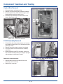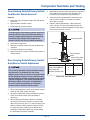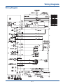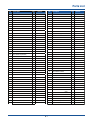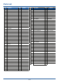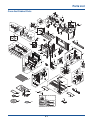
1
Technical Service Manual Over The Range Microwave Oven Models E30MH65GPSA E30MH65GSSA Publication #5995535480 P/N 316439276 June 2009 Basic Information Safe Servicing Practices Avoid personal injury and/or property damage by observing important Safe Servicing Practices. Following are some limited examples of safe practices: 1. DO NOT attempt a product repair if you have any doubts as to your ability to complete the repair in a safe and satisfactory manner. 2. Always Use The Correct Replacement Parts as indicated in the parts documentation. Substitutions may defeat compliance with Safety Standards Set For Home Appliances. Do not exceed maximum recommended wattage on light bulb replacements. Doing so could blow fuses and/or damage transformers. 3. Before servicing or moving an appliance: • Remove power cord from the electrical outlet, trip circuit breaker to the OFF position, or remove fuse. 4. Never interfere with the proper operation of any safety device. 5. Use ONLY REPLACEMENT PARTS CATALOGED FOR THIS APPLIANCE. Substitutions may defeat compliance with Safety Standards Set For Home Appliances. 6. GROUNDING: The standard color coding for safety ground wires is GREEN, or GREEN with YELLOW STRIPES. Ground leads are not to be used as current carrying conductors. It is EXTREMELY important that the service technician reestablish all safety grounds prior to completion of service. Failure to do so will create a hazard. 7. Prior to returning the product to service, ensure that: • All electrical connections are correct and secure. • All electrical leads are properly dressed and secured away from sharp edges, high-temperature components, and moving parts. • All non-insulated electrical terminals, connectors, heaters, etc. are adequately spaced away from all metal parts and panels. • All safety grounds (both internal and external) are correctly and securely connected. • All panels are properly and securely reassembled. © 2009 Electrolux Home Products, Inc. 1-1 Basic Information This Manual has been prepared to provide Electrolux Service Personnel with Operation and Service Information for Electrolux Microwave Ovens E30MH65GPSA and E30MH65GSSA. Table of Contents Section 1 Basic Information Section 4 Component Teardown and Testing Safe Servicing Practices.......................................... 1-1 Table of Contents .................................................... 1-2 Warnings and Safety Information ............................ 1-3 Precautions To Be Observed Before And During Servicing To Avoid Possible Exposure To Excessive Microwave Energy .................................. 1-4 Before Servicing ...................................................... 1-4 Danger High Voltage ............................................... 1-4 Before Servicing ...................................................... 1-5 When Testing Is Completed .................................... 1-5 Microwave Measurement Procedure USA .............. 1-6 Microwave Measurement Procedure Canada ......... 1-7 Product Specification ............................................... 1-8 Grounding Instructions ............................................ 1-9 Discharging Capacitor ............................................. 1-9 Oven Diagram ......................................................... 1-10 Accessory Components........................................... 1-10 Warnings and Cautions ........................................... Removing Oven From Wall ..................................... Grille Removal ......................................................... Outer Case Removal ............................................... High Voltage Transformer and Fan Motor Assembly Removal .................................................. High Voltage Transformer Testing........................... Low Voltage Transformer Testing ........................... Magnetron Removal ................................................ Magnetron Testing................................................... Output Power of Magnetron .................................... High Voltage Capacitor Testing ............................... High Voltage Diode Testing ..................................... Main Relay and Power Control Relay Testing ......... Vent Blower Testing ................................................ Run Capacitor.......................................................... Vent Blower Removal .............................................. Door “C” Removal.................................................... Door “E” Removal .................................................... Main Fuse Removal................................................. Drive Motor Removal ............................................... Stirrer Motor Removal ............................................. Stirrer Removal........................................................ Thermal Cutout Removal......................................... Oven Thermal Cutout ........................................... Hood Thermal Cutout ........................................... Bottom Thermal Cutout ........................................ Magnetron Thermal Cutout .................................. Sensor Removal ...................................................... Convection Fan Assembly ....................................... Servicing The Touch Control Panel ......................... Control Box Removal............................................... P.C.B Assembly Removal ....................................... Door Sensing Switch/Primary Switch/ And Monitor Switch Removal .................................. Door Sensing Switch/Primary Switch/ And Monitor Switch Adjustment............................... Section 2 Installation and Operation Installation ............................................................... Fan Operation.......................................................... Automatic Fan ...................................................... Vent Blower .......................................................... Lighting and Filters .................................................. Cooktop Lights ..................................................... Oven Light ............................................................ Grease Filters ....................................................... Grille Removal ...................................................... Removing Charcoal Filter ..................................... 2-1 2-1 2-1 2-1 2-2 2-2 2-2 2-2 2-2 2-2 Section 3 Troubleshooting and Error Codes Warnings and Cautions ........................................... Troubleshooting Guide Chart .................................. Error Codes ............................................................ 3-1 3-2 3-4 4-1 4-2 4-2 4-2 4-3 4-3 4-3 4-4 4-4 4-4 4-5 4-5 4-5 4-6 4-6 4-6 4-7 4-7 4-8 4-8 4-8 4-8 4-9 4-9 4-9 4-9 4-9 4-10 4-10 4-11 4-12 4-12 4-13 4-13 Section 5 Wire Diagrams Wiring Diagram ........................................................ 5-1 Section 6 Parts List Parts Listing ............................................................. Oven And Cabinet Parts Exploded View ................. 1-2 6-1 6-3 Basic Information CERTAIN INITIAL PARTS ARE INTENTIONALLY NOT GROUNDED AND PRESENT A RISK OF ELECTRICAL SHOCK ONLY DURING SERVICING. SERVICE PERSONNEL - DO NOT CONTACT THE FOLLOWING PARTS WHILE THE APPLIANCE IS ENERGIZED: INVERTER UNIT, THAT INCLUDES HIGH VOLTAGE CAPACITOR, HIGH VOLTAGE POWER TRANSFORMER, HIGH VOLTAGE RECTIFIER, HEAT SINK, ETC., AND MAGNETRON, HIGH VOLTAGE HARNESS ETC.; IF PROVIDED, FAN ASSEMBLY, COOLING FAN MOTOR. ALL THE PARTS MARKED “*” ON PARTS LIST ARE USED AT VOLTAGES MORE THAN 250V. REMOVAL OF THE OUTER WRAPPER GIVES ACCESS TO VOLTAGE ABOVE 250V. ALL THE PARTS MARKED “Ä” ON PARTS LIST MAY CAUSE UNDUE MICROWAVE EXPOSURE, BY THEMSELVES, OR WHEN THEY ARE DAMAGED, LOOSENED OR REMOVED. THIS SERVICE MANUAL IS INTENDED FOR USE BY PERSONS HAVING ELECTRICAL AND MECHANICAL TRAINING AND A LEVEL OF KNOWLEDGE OF THESE SUBJECTS GENERALLY CONSIDERED ACCEPTABLE IN THE APPLIANCE REPAIR TRADE. ELECTROLUX HOME PRODUCTS CANNOT BE RESPONSIBLE, NOR ASSUME ANY LIABILITY, FOR INJURY OR DAMAGE OF ANY KIND ARISING FROM THE USE OF THIS MANUAL. NEVER OPERATE THE OVEN UNTIL THE FOLLOWING POINTS ARE ENSURED. (A) THE DOOR IS TIGHTLY CLOSED. (B) THE DOOR BRACKETS AND HINGES ARE NOT DEFECTIVE. (C) THE DOOR PACKING IS NOT DAMAGED. (D) THE DOOR IS NOT DEFORMED OR WARPED. (E) THERE IS NO OTHER VISIBLE DAMAGE WITH THE OVEN. SERVICING AND REPAIR WORK MUST BE CARRIED OUT ONLY BY TRAINED SERVICE PERSONNEL. SERVICEMEN SHOULD REMOVE THEIR WATCHES WHENEVER WORKING CLOSE TO OR REPLACING THE MAGNETRON. All repairs should be done in accordance with the procedures described in this manual. This product complies with Federal Performance Standard 21 CFR Subchapter J(DHHS). Never defeat any of the B+ voltage interlocks. Do not apply AC power to the unit (or any of its assemblies) unless all solid-state heat sinks are correctly installed. Some semiconductor (“solid state”) devices are easily damaged by static electricity. Such components are called Electrostatically Sensitive Devices (ESDs). Examples include integrated circuits and field-effect transistors. Immediately before handling any semiconductor components or assemblies, drain the electrostatic charge from your body by touching a known earth ground. 1-3 Basic Information Precautions To Be Observed Before And During Servicing To Avoid Possible Exposure To Excessive Microwave Energy (a) Do not operate or allow the oven to be operated with the door open. (b) Make the following safety checks on all ovens to be serviced before activating the magnetron or other microwave source, and make repairs as necessary: (1) interlock operation, (2) proper door closing, (3) seal and sealing surfaces (arcing, wear, and other damage), (4) damage to or loosening of hinges and latches, (5) evidence of dropping or abuse. (c) Before turning on microwave power for any service test or inspection within the microwave generating compartments, check the magnetron, wave guide or transmission line, and cavity for proper alignment, integrity, and connections. (d) Any defective or misadjusted components in the interlock, monitor, door seal, and microwave generation and transmission systems shall be repaired, replaced, or adjusted by procedures described in this manual before the oven is released to the owner. (e) A microwave leakage check to verify compliance with the Federal Performance Standard should be performed on each oven prior to release to the owner. Before Servicing Before servicing an operative unit, perform a microwave emission check as per the Microwave Measurement Procedure outlined in this service manual. If microwave emissions level is in excess of the specified limit, contact ELECTROLUX HOME PRODUCTS, INC. immediately. If the unit operates with the door open, service person should: 1) Tell the user not to operate the oven. 2) Contact Electrolux HOME PRODUCTS, INC. and Food and Drug Administration’s Center for Devices and Radiological Health immediately. Service personnel should inform ELECTROLUX HOME PRODUCTS, INC. of any certified unit found with emissions in excess of 4mW/cm2. The owner of the unit should be instructed not to use the unit until the oven has been brought into compliance. DANGER HIGH VOLTAGE Do not energize a microwave oven with the outer case cabinet removed, because a microwave oven generates high voltage in the circuit. If you intend to operate the oven employing the high frequency switching power converter circuit, you should take special precautions to avoid an electrical shock hazard. The high voltage transformer, high voltage capacitor and high voltage diode have energized high voltage potential of approximately 8KV. The aluminium heat sink is connected to the switching power transistor collector pole, and has an energized high voltage potential of approximately 650V peak. DO NOT ACCESS THE HIGH VOLTAGE TRANSFORMER, HIGH VOLTAGE CAPACITOR, HIGH VOLTAGE DIODE AND HEAT SINK WHEN THE POWER SUPPLY IS CONNECTED TO AN ELECTRICAL OUTLET. 1-4 Basic Information MICROWAVE OVENS CONTAIN CIRCUITRY CAPABLE OF PRODUCING VERY HIGH VOLTAGE AND CURRENT. CONTACT WITH THE FOLLOWING PARTS MAY RESULT IN A SEVERE, POSSIBLY FATAL, ELECTRICAL SHOCK. INVERTER UNIT, THAT INCLUDES HIGH VOLTAGE CAPACITOR, HIGH VOLTAGE POWER TRANSFORMER, HIGH VOLTAGE RECTIFIER, HEAT SINK ETC., AND MAGNETRON, HIGH VOLTAGE HARNESS ETC.. READ THE SERVICE MANUAL CAREFULLY AND FOLLOW ALL INSTRUCTIONS. Don't Touch ! Danger High Voltage Before Servicing When Testing Is Completed 1. Disconnect the power supply cord, and then remove outer case. 2. Open the door and block it open. 3. Discharge high voltage capacitor. 1. To discharge the high voltage capacitor, wait for 60 seconds and then short-circuit the connection of the high-voltage capacitor (that is the connecting lead of the high-voltage rectifier) against the chassis with the use of an insulated screwdriver. Whenever troubleshooting is performed, the power supply must be disconnected. It may, in some cases, be necessary to connect the power supply after the outer case has been removed, in this event: 1. Disconnect the oven power supply cord and then remove the outer case. 2. Open the door and block it open. 3. Discharge high voltage capacitor. 4. Disconnect leads to the primary of the inverter unit. 5. Ensure that these leads remain isolated from other components and oven chassis by using insulation tape. 6. After that procedure, reconnect the power supply cord. 2. 3. Disconnect the power supply cord, and then remove outer case. Open the door and block it open. Discharge high voltage capacitor. To discharge the high voltage capacitor, wait for 60 seconds and then short-circuit the connection of the high-voltage capacitor (that is the connecting lead of the high-voltage rectifier) against the chassis with the use of an insulated screwdriver. 4. 5. 6. 7. Reconnect leads to the primary of the inverter unit. Reinstall the outer case (cabinet). Reconnect the power supply cord after the outer case is installed. Run the oven and check all functions. After repairing 1. Reconnect all leads removed from components during testing. 2. Reinstall the outer case (cabinet). 3. Reconnect the power supply cord after the outer case is installed. 4. Run the oven and check all functions. Microwave ovens should not be run empty. To test for the presence of microwave energy within a cavity, place a cup of cold water on the oven turntable, close the door and set the power to HIGH and then set the microwave timer for two (2) minutes. When the two minutes has elapsed (timer at zero) carefully check that the water is now hot. If the water remains cold carry out Before Servicing procedure and re-examine the connections to the component being tested. 1-5 Basic Information Microwave Measurement Procedure (USA) A. Requirements: 1) Microwave leakage limit (Power density limit): The power density of microwave radiation emitted by a microwave oven should not exceed 1 mW/cm2 at any point 5 cm or more from the external surface of the oven, measured prior to acquisition by a purchaser, and thereafter (through the useful life of the oven), 5 mW/cm2 at any point 5 cm or more from the external surface of the oven. 2) Safety interlock switches: Primary interlock switch shall prevent microwave radiation emission in excess of the requirement as above mentioned, secondary interlock switch shall prevent microwave radiation emission in excess of 5 mW/cm2 at any point 5 cm or more from the external surface of the oven. B. Preparation for testing: Before beginning the actual measurement of leakage, proceed as follows: 1) Make sure that the actual instrument is operating normally as specified in its instruction booklet. Important: Survey instruments that comply with the requirement for instrumentation as prescribed by the performance standard for microwave ovens, 21 CFR 1030.10(c)(3)(i), must be used for testing. 2) Place the oven tray in the oven cavity. 3) Place the load of 275±15 ml (9.8 oz) of tap water initially at 20°±5C (68±9°F) in the center of the oven cavity. The water container shall be a low form of 600 ml (20 oz) beaker with an inside diameter of approx. 8.5 cm (3-1/2 in.) and made of an electrically nonconductive material such as glass or plastic. The placing of this standard load in the oven is important not only to protect the oven, but also to insure that any leakage is measured accurately. 4) Set the cooking control on Full Power Cooking Mode. 5) Close the door and select a cook cycle of several minutes. If the water begins to boil before the survey is completed, replace it with 275 ml of cool water. C. Leakage test: Closed-door leakage test (microwave measurement) 1) Grasp the probe of the survey instrument and hold it perpendicular to the gap between the door and the body of the oven. 2) Move the probe slowly, not faster than 1 in./sec. (2.5 cm/sec.) along the gap, watching for the maximum indication on the meter. 3) Check for leakage at the door screen, sheet metal seams and other accessible positions where the continuity of the metal has been breached (eg., around the switches, indicator, and vents). While testing for leakage around the door pull the door away from the front of the oven as far as is permitted by the closed latch assembly. 4) Measure carefully at the point of highest leakage and make sure that the highest leakage is no greater than 4 mW/cm2, and that the primary interlock switch and secondary interlock switch do turn the oven OFF before any door movement. NOTE: After servicing, record data on service invoice and microwave leakage report. 1-6 Basic Information Microwave Measurement Procedure (Canada) After adjustment of the door switches are completed individually or collectively, switch test and microwave leakage test must be performed with survey instrument and test result must be confirmed to meet the requirement of the performance standard for microwave ovens as under mentioned. A. Requirements: Every microwave oven shall function in such a manner that when the oven is fully assembled and operating with its service controls and user controls adjusted to yield the maximum output, the leakage radiation, at all points at least 5 cm. from the external surface of the oven, does not exceed: 1) 1.0 mW/cm2 with the test load of 275 ± 15 ml of water at an initial temperature 20 ±5°C. 2) 5.0 mW/cm2 when the outer enclosure is removed with a test load of 275 ± 15 ml of water at an initial temperature 20±5°C. 3) 5.0 mW/cm2 without a test load. B. Preparation for testing: Before beginning the actual measurement of leakage, proceed as follows: 1) Make sure that the actual instrument is operating normally as specified in its instruction booklet. Survey instruments that comply with the requirement for instrumentation as prescribed by CSA and NHW performance standard for microwave ovens must be used for testing recommended instruments are, NARDA 8100 and NARDA 8200. 2) Place the oven tray in the oven cavity. 3) Place the load of 275±15 ml (9.8 oz) of tap water initially at 20°±5C (68±9°F) in the center of oven cavity. The water container shall be a low form of a 600 ml (20 oz) beaker with an inside diameter of approx. 8.5 cm (3-1/2 in.) and made of an electrically nonconductive material such as glass or plastic. The placing of this standard load in the oven is important not only to protect the oven, but also to insure that any leakage is measured accurately. 4) Set the cooking control on Full Power Cooking Mode. 5) Close the door and select a cook cycle of several minutes. If the water begins to boil before the survey is completed, replace it with 275 ml of cool water. C. Leakage test with enclosure installed: 1) Grasp probe of survey instrument and hold it perpendicular to gap between door and the body of the oven. 2) Move the probe slowly, not faster than 2.5 cm/sec. along the gap, watching for maximum indication on meter. 3) Check for leakage at the door screen, sheet metal seams and other accessible positions where the continuity of the metal has been breached (eg., around the switches, indicator, and vents). While testing for leakage around door, pull door away from the front of the oven as far as is permitted by the closed latch assembly. 4) Measure carefully at the point of highest leakage and make sure that the highest leakage is no greater than 4 mW/cm2, and that the primary interlock switch and secondary interlock switch do turn the oven OFF before any door movement. D. Leakage test without enclosure: 1) Remove the enclosure (cabinet). 2) Grasp the probe of the survey instrument and hold it perpendicular to all mechanical and electric parts of the oven that is accessible to the user of the oven including, but not limited to, the waveguide, cavity seams, magnetron gap between the door and the body of the oven. 3) Move probe slowly, not faster than 2.5 cm/sec. along the gap, watching for the maximum indication on meter. 4) Measure carefully at the point of highest leakage and make sure that the highest leakage is under 5 mW/cm2. CAUTION: Special attention should be given to avoid electrical shock because HIGH VOLTAGE is generated during this test. E. No Load test 1) Operate the oven without a load and measure the leakage by the same method as the above test procedure “ Leakage test with enclosure installed” 2) Make sure that the highest leakage should not exceed 5 mW/cm2. NOTE: After servicing, record data on service invoice and microwave leakage report. 1-7 Basic Information Product Specification Item Description Power Requirements (USA)120 Volts / 13.0 Amperes / 1600 Watt 60 Hertz Single phase, 3 wire grounded Power Output 950 watts (IEC 705 Test Procedure) Operating frequency of 2450MHz Outside Dimensions) Width 29-7/8” Lighting 2- 20 Watt halogen bulbs Cooling Method Cooling Fan Motor Control Complement Touch Control System Clock ( 1:00 - 12:59 ) Timer (0 - 99 min. 99 seconds) Microwave Power for Variable Cooking Repetition Rate; P-HI Full power throughout the cooking time P-90 approx. 90% of Full Power P-80 approx. 80% of Full Power P-70 approx. 70% of Full Power P-60 approx. 60% of Full Power P-50 approx. 50% of Full Power P-40 approx. 40% of Full Power P-30 approx. 30% of Full Power P-20 approx. 20% of Full Power P-10 approx. 10% of Full Power P-0 No power throughout the cooking time Height 16-15/16” Depth 15-7/16” Sensor modes pads, Auto cook pads, Timer on-off pad, Set clock pad, User Pref pad, Quick start pad, Number selection pads, Power Level pad, Add 30 sec pad, Stop/Clear pad, Melt or soften pad, and Start/Enter pad. Snacks pad, Popcorn pad, Reheat pad, Pizza slice pad, Baked potato pad, Auto defrost pad, Turntable On/Off pad Safety Standard UL Listed FCC Authorized DHHS Rules, CFR, Title 21, Chapter 1, Subchapter J Canadian Standards Association Health CANADA, Industry Canada Net Weight 74.74 lbs. 1-8 Basic Information Grounding Instructions Discharging Capacitor This oven is equipped with a three prong grounding plug. It must be plugged into a wall receptacle that is properly installed and grounded in accordance with the National Electrical Code, local codes and ordinances. In the event of an electrical short circuit, grounding reduces the risk of electric shock by providing an escape wire for the electric current. 1. IMPROPER USE OF THE GROUNDING PLUG CAN RESULT IN A RISK OF ELECTRIC SHOCK. Electrical Requirements The oven is equipped with a 3-prong grounding plug. DO NOT UNDER ANY CIRCUMSTANCES CUT OR REMOVE THE GROUNDING PIN FROM THE PLUG. The power supply cord and plug must be connected to a separate 120 Volt AC, 60 Hz, 15 Amp. or more dedicated line, using a grounded receptacle. When installing this appliance, observe all applicable codes and ordinances. A short power-supply cord is provided to reduce risks of becoming entangled in or tripping over a longer cord. Where a two-pronged wall-receptacle is encountered, it is the personal responsibility and obligation of the customer to contact a qualified electrician and have it replaced with a properly grounded three-pronged wall receptacle or have a grounding adapter properly grounded and polarized. Do not attempt to measure any of the high voltages, this includes the filament voltage of the magnetron. High voltage is present during any cook cycle. Before touching any components or wiring, always unplug the oven and discharge the high voltage capacitor (See Figure 1-2). 2. The high-voltage capacitor remains charged about 30 seconds after disconnection. Short the negative terminal of the high-voltage capacitor to the oven chassis. (Use an insulated screwdriver.) 3. High voltage is maintained within specified limits by close-tolerance, safety-related components and adjustments. If the high voltage exceeds the specified limits, check each of the special components. High Voltage Capacitor If an extension cord must be used, it should be a 3-wire, 15 amp. or more rated cord. Do not drape over a countertop or table where it can be pulled on by children or tripped over accidentally. 3-Pronged Plug High Voltage Warning! Figure 1-2. Capacitor Discharging Grounded Receptacle Box Grounding Pin 3-Pronged Receptacle Figure 1-1. Electrical Connection 1-9 Basic Information Touch Control Panel Oven Diagram Door Window with Handle Metal Shield Cooking Guide Drip Pan 4- Display Window Vent Grille Rack 1- Background 2- Touchpad Text 3- Touchpad Circles/Semi-circles Door Safety Lock System Glass Model and Turntable Serial Number Plate 2- Numeric Keypad Oven Control Panel 5- “Cancel” Touchpad 3- Secondary Touchpads 758 mm Accessory Components 419 mm 404.8 mm Unpack the microwave oven and check to make sure that you have all the parts listed below. If any part is missing or broken, a replacement can be ordered. 389.7 mm 1. 2. 3. 4. 5. 6. 7. 8. 9. 10. 11. 12. 1-10 Registration Card Use and Care Guide Installation Instructions Top Template Wall Template Glass Tray Roller Guide Ring Charcoal filter Hardware-kit Grease Filters Shelf Exhaust Adaptor Drip pan Installation and Operation Installation The microwave oven is supported by a special bracket assembly (mounting system) supplied with the oven. The bracket assembly must be mounted to the wall with toggle bolts through the wall, and a lag screw into a wall stud. After the bracket assembly is installed, the unit can be slid over the two rails of the bracket assembly. Two bolts are run down through the cabinet bottom and into the oven case to pull the oven up against the cabinet bottom. NOTE: For easier removal and personal safety it is recommended that two people remove this product. Mounting Plate Figure 2-1. Mounting Oven To Bracket The mounting surface must be capable of supporting the cabinet load, and in addition to the 64 pound product, an additional load of up to 50 pounds for a total weight of 114 pounds. This product cannot be installed to cabinet arrangements such as an island or peninsula. It must be mounted to both a top cabinet and wall. Fan Operation AUTOMATIC FAN An automatic fan feature protects the microwave from too much heat rising from the cooktop below it. The fan will automatically turn off when the internal parts are cool. It may stay on for 30 minutes or more after the cooktop and microwave controls are turned off. VENT BLOWER The vent or exhaust blower is located at the top of the oven. It is shipped for recirculating exhaust but can be changed to rear or vertical exhaust. The blower is a two speed (HI-LO) capacitor run blower assembly located on top of the microwave oven. The blower is operated by low voltage relays located on the smart board. The blower motor has 3 winding which can be tested for continuity from the front by removing the top grille and opening the control panel. (See Section 4) 2-1 Installation and Operation Lighting and Filters COOKTOP LIGHTS One 20-watt halogen bulb is located on the bottom. The bulb is user replaceable by removing one screw and lowering access cover. The bulb could be difficult to remove when replaced for the first time. A silicone glue is used to secure them during shipping. (See Figure 2-2) Remove Screw Figure 2-2. Cooktop Bulb Removal OVEN LIGHT A 20-watt halogen bulb is located in the top of the oven cavity at the front. It is user replaceable by removing the top grill (2 screws on front of outer case). The bulb is accessible by removing a metal cover. (See Figure 2-3) GREASE FILTERS The metal filter traps grease released by foods on the cooktop. They also prevent flames from foods on the cooktop from damaging the inside of the microwave. For this reason, the filters must ALWAYS be in place when the hood vent fan is used. The grease filter should be cleaned once a month, or as needed. (See Figure 2-4) Figure 2-3. Oven Light Removal Charcoal Filter GRILLE REMOVAL The top full-width grille is removable for service to some components, such as : oven light, cavity T.C.O. vent motor capacitor and fuse. To remove grille: (See Figure 2-5) 1. Disconnect oven power. 2. Remove screws (2) from grille outer case. 3. Lift off grille. Reusable Grease Filters Figure 2-4. Filter locations REMOVING CHARCOAL FILTER To remove the charcoal filter, disconnect power at the main fuse or circuit breaker panel or pull the plug. Remove the top grille by removing the 2 screws that hold it in place. Slide the filter towards the front of the oven and remove from unit. (See Figure 2-6) Remove 2 grille screws to remove grille. Figure 2-5. Grille Removal Figure 2-6. Charcoal Filter Removal 2-2 Troubleshooting and Error Codes Troubleshooting Guide If the fuse is blown by the Interlock Monitor Switch: Replace all of the following at the same time: Primary, door sensing switch and power relay, as well as the Interlock Monitor Switch. The correct adjustment of these switches is described elsewhere in this manual. Make sure the fuse has the correct rating for the particular model being repaired. WHENEVER TROUBLESHOOTING IS PERFORMED WITH THE POWER SUPPLY CORD DISCONNECTED. IT MAY IN, SOME CASES, BE NECESSARY TO CONNECT THE POWER SUPPLY CORD AFTER THE OUTER CASE HAS BEEN REMOVED, IN THIS EVENT: 1. Disconnect the power supply cord, and then remove outer case. 2. Open the door and block it open. 3. To discharge high voltage capacitor, wait for 60 seconds and then short-circuit the connection of the high-voltage capacitor (that is the connecting lead of the high-voltage rectifier) against the chassis with the use of an insulated screwdriver. 4. Disconnect the leads to the primary of the power transformer. 5. Ensure leads remain isolated from other components and oven chassis by using insulation tape. 6. After that procedure, reconnect the power supply cord. WHEN THE TESTING IS COMPLETED: 1. Disconnect the power supply cord, and then remove outer case. 2. Open the door and block it open. 3. To discharge high voltage capacitor, wait for 60 seconds and then short-circuit the connection of the high-voltage capacitor (that is the connecting lead of the high-voltage rectifier) against the chassis with the use of an insulated screwdriver. 4. Reconnect the leads to the primary of the power transformer. 5. Reinstall the outer case (cabinet). 6. Reconnect the power supply cord after the outer case is installed. 7. Run the oven and check all functions. When checking the continuity of the switches or transformer, disconnect one lead wire from these parts and then check continuity without the power source on. To do otherwise may result in a false reading or damage to your meter. Do not touch any part of the circuit or the control circuit board, since static discharge may damage it. Always touch ground while working on it to discharge any static charge built up. Microwave ovens should not be run empty. To test for the presence of microwave energy within a cavity, place a cup of cold water on the oven turntable, close the door and set the power to HIGH and then set the microwave timer for two (2) minutes. When the two minutes has elapsed (timer at zero) carefully check that the water is now hot. If the water remains cold carry out Before Servicing procedure and re-examine the connections to the component being tested. When all service work is completed and the oven is fully assembled, the microwave power output should be checked and a microwave leakage test should be carried out. 3-1 Troubleshooting and Error Codes Symptom Cause Corrections Oven is dead. Fuse is OK. No display and no operation at all. 1. 2. 3. 4. Open or loose lead wire harness. Open thermal cutout (Magnetron) Open low voltage transformer. Defective Assembly PCB. Check fan motor when thermal cutout is defective. Check Assembly PCB when low voltage transformer is defective. See Section 4: Low Voltage Transformer Testing No display and no operation at all. Fuse is blown. 1. 2. 3. 4. 5. Shorted lead wire harness Defective primary latch switch (NOTE 1) Defective monitor switch (NOTE1) Shorted H.V. Capacitor Shorted H.V. Transformer (NOTE2) Check adjustment of primary, interlock monitor, power relay, door sensing switch. See Section 4: Main Relay and Power Control Relay Testing, and Door Sensing Switch/Primary Switch/ And Monitor Switch Adjustment NOTE 1: All of these switches must be replaced at the same time. (refer to adjustment instructions) Check continuity of power relay contacts and if it has continuity, replace power relay also. NOTE 2: When H.V. Transformer is replaced, check diode and magnetron also. Oven does not accept key input (Program) 1. Key input is not in-Sequence 2. Open or loose connection of membrane key pad to Ass’y PCB 3. Shorted or open membrane panel 4. Defective Ass’y PCB Refer to operation procedure. Replace PCB main. See Section 4: P.C.B Assembly Removal Timer starts countdown but no microwave oscillation. (No heat while oven lamp and fan motor turn on.) 1. Off-alignment of latch switches 2. Open or loose connection of high voltage circuit especially magnetron filament circuit NOTE: Large contact resistance will bring lower magnetron filament voltage and cause magnetron to lower output and/or intermittent oscillation. 3. Defective high voltage components: H.V. Transformer H.V. Capacitor H.V. Diode, H.V. Fuse Magnetron 4. Open or loose wiring of power relay 5. Defective primary latch switch 6. Defective power relay or Ass’y PCB. Adjust door and latch switches. See Section 4: Door Sensing Switch/ Primary Switch/ And Monitor Switch Adjustment See Section 4: Magnetron Testing See Section 4: High Voltage Transformer Testing, Low Voltage Transformer Testing See Section 4: High Voltage Capacitor Testing See Section 4: High Voltage Diode Testing Check high voltage component according to component test procedure and replace if it is defective. Replace PCB main. Oven lamp and fan motor turn on. 1. Misadjustment or loose wiring of primary latch switch 2. Defective primary latch switch. Adjust door and latch switches. See Section 4: Door Sensing Switch/ Primary Switch/ And Monitor Switch Adjustment 3-2 Troubleshooting and Error Codes Symptom Cause Corrections Oven can program but timer does not start. 1. Open or loose wiring of secondary interlock switch 2. Off-alignment of primary interlock 3. Defective secondary interlock S/W. Adjust door and interlock switches. See Section 4: Door Sensing Switch/ Primary Switch/ And Monitor Switch Adjustment Microwave output is low: 1. Decrease in power source voltage. Oven takes longer time to 2. Open or loose wiring of magnetron cook food. filament circuit. (Intermittent oscillation) 3. Aging of magnetron Consult electrician. Check wiring. See Section 4: Magnetron Testing Replace magnetron. Fan motor turns on when Loose wiring of door sensing switch. plugged in. Check wire of door sensing switch. See Section 4: Door Sensing Switch/ Primary Switch/ And Monitor Switch Adjustment Oven does not operate Defective Assembly PCB and return to the plugged in mode. Replace PCB main. Loud buzzing noise can be heard. Tighten screws of fan motor. Tighten screws of H.V.Transformer. See Section 4: High Voltage Diode Testing : Replace H.V. Diode if needed. 1. Loose fan and fan motor 2. Loose screws on H.V.Transformer 3. Shorted H.V.Diode Turntable motor does not 1. Open or loose wiring of turntable rotate. motor. 2. Defective turntable motor. Replace turntable motor. Oven stops operation during cooking. 1. Open or loose wiring of primary interlock switch. 2. Operation of thermal cutout (Magnetron) Adjust door and latch switches. See Section 4: Magnetron Testing See Section 4: Door Sensing Switch/ Primary Switch/ And Monitor Switch Adjustment Sparks 1. Metallic ware or cooking dishes touching on the oven wall. 2. Ceramic ware trimmed with gold or silver powder also causes sparks. Inform the customer. Do not use any type of cookware with metallic trimming. Uneven cooking Uneven intensity of microwave due to its characteristics. Wrap thinner parts of the food with aluminum foil. Use plastic wrap or cover with a lid. Stir once or twice while cooking foods such as soup, cocoa, or milk. Noise from the turntable motor when it starts to operate. Noise may result from the motor. Replace turntable motor. 3-3 Troubleshooting and Error Codes Error Codes Error Code E-24 Contents If overheat during cooking causes to reach 500˚F, it stops all modes of cooking, causes ‘E-24’ error, and converts to cancel mode. E-22 ‘Short Error’ of thermal sensor E-21 ‘Open Error’ of thermal sensor E-03 E-23 - If the WARM, CONVECTION, PREHEAT and BROIL do not reach over 217 of HEX value within 3 minutes, it causes ‘E3’ error and converts to cancel mode. If the PREHEAT does not reach the preset temperature within 30 minutes, it causes ‘E4’ error and converts to cancel mode. -SE- Key Short Error. E-11 ‘Open Error’ of gas sensor. E-12 ‘Short Error’ of gas sensor. Cause of Troubles Sensor Poor 3-4 Convection Motor Open Convection Heater Open Assembly Casing Not Installed Correctly Component Teardown and Testing TO PREVENT AN ELECTRIC SHOCK, TAKE THE FOLLOWING PRECAUTIONS: 1. BEFORE WIRING: 1) Disconnect the power supply. 2) Open the door and wedge the door open. 3) Discharge the high voltage capacitor and wait for 60 seconds. 2. DO NOT LET WIRE LEADS TOUCH TO THE FOLLOWING PARTS: 1) High voltage parts: Magnetron, High voltage transformer, High voltage capacitor and High voltage rectifier assembly. 2) Hot parts: Oven lamp, Magnetron, High voltage transformer and Oven cavity. 3) Sharp edge: Bottom plate, Oven cavity, Waveguide flange, Chassis support and other metallic plates. 4) Movable parts (to prevent a fault) Fan blade, Fan motor, Switch, Switch lever, Open button. 3. Do not catch the wire leads in the outer case cabinet. 4. Insert the positive lock connector completely until its pin is locked. Make sure that the wire leads should not come off even if the wire leads are pulled. 5. To prevent an error function, connect the wire leads correctly, referring to the Pictorial Diagram. AVOID POSSIBLE EXPOSURE TO MICROWAVE ENERGY. PLEASE FOLLOW INSTRUCTIONS BELOW BEFORE OPERATING THE OVEN. 1. Disconnect the power supply cord. 2. Make sure that a definite” click” can be heard when the microwave oven door is unlatched. (Hold the door in a closed position with one hand, then push the door open button with the other, this causes the latch leads to rise, it is then possible to hear a “click’ as the door switches operate.) 3. Visually check the door and cavity face plate for damage (dents, cracks, signs of arcing etc.). Carry out any remedial work that is necessary before operating the oven. DO NOT OPERATE THE OVEN IF ANY OF THE FOLLOWING CONDITIONS EXIST; 1. Door does not close firmly. 2. Door hinge, support or latch hook is damaged. 3. The door gasket or seal is damaged. 4. The door is bent or warped. 5. There are defective parts in the door interlock system. 6. There are defective parts in the microwave generating and transmission assembly. 7. There is visible damage to the oven. DO NOT OPERATE THE OVEN: 1. Without the RF gasket (Magnetron). 2. If the wave guide or oven cavity are not intact. 3. If the door is not closed. 4. If the outer case (cabinet) is not fitted. Disconnect oven from power supply before removing outer case. Discharge high voltage capacitor before touching any oven components or wiring after removing outer case. 4-1 Component Teardown and Testing Removing Oven From Wall Oven weights 74 lbs. Requires 2 people for removal. Oven is hooked on metal tabs at bottom of wall mounting plate and fastened to cabinet by (3) top cabinet bolts. 1. Disconnect power cord. For top vented models, disconnect duct and remove damper assembly. 2. Remove (3) top cabinet bolts. 3. Pull unit forward slowly providing adequate support to prevent dropping unit during removal of the last top cabinet bolt. The oven must be removed from wall when removing the magnetron, motor assembly, vent blower and high voltage transformer. (See Figure 4-1) Figure 4-1. Wall Mounting Components Remove 2 grille screws to remove grille. Grille Removal The top full-width grille is removable for service to some components, such as: oven light, oven thermal cut-out, vent motor capacitor and fuse. To remove grille: 1. Disconnect oven power. 2. Remove screws (2) from grille outer case. (See Figure 4-2) 3. Lift off grille. Figure 4-2. Grille Screws Outer Case Removal 1. Disconnect oven from power supply before removing outer case. 2. Discharge the high voltage capacitor before touching any oven components or wiring. To remove the outer case, proceed as follows; 1. Disconnect the power supply cord. 2. Open the oven door and block it open. 3. Remove (18) screws from the outer-case. 4. Lift entire outer case from the unit. 4-2 Component Teardown and Testing High Voltage Transformer and Fan Motor Assembly Removal 1. Disconnect oven from power supply and remove from wall. 2. Remove the outer case. 3. Discharge the high voltage capacitor. To discharge the high voltage capacitor, wait for 60 seconds and then short-circuit the connection of the high-voltage capacitor (that is the connecting lead of the high-voltage rectifier) against the chassis with the use of an insulated screwdriver. 1. High voltage is present at the high voltage terminals during any cook cycle. 2. It is neither necessary nor advisable to attempt measurement of the high voltage. 3. Before touching any oven components or wiring, always unplug the oven from its power source and discharge the high voltage capacitor. High Voltage Transformer Testing 1. Remove connectors from the transformer terminals and check continuity. (See Figure 4-5) 2. Normal resistance readings at 20°C are as follows: 4. Disconnect all the leads. 5. Remove (2) screws from the fan motor assembly. (See Figure 4-3) 6. Remove (3) screws from the duct-side. 7. Remove the duct-side. 8. Take out the fan motor. 9. Remove (4) screws from the H.V. Transformer. 10. Take out the H.V. Transformer. Secondary Terminals Filament Terminal Screw Top Screw Back Screw Primary Terminals Figure 4-5. High Voltage Transformer Testing Screw Side Transformer Screws (2 each Side) Duct Side Figure 4-3. High Voltage Transformer Removal Low Voltage Transformer Testing 1. The low voltage transformer is located on the control circuit board. 2. Remove the low voltage transformer from the PCB assembly and check continuity. 3. Normal resistor reading is shown in the table. Terminals Figure 4-4. High Voltage Capacitor 4-3 Resistance Component Teardown and Testing Magnetron Removal Magnetron Antenna 1. Disconnect the power supply cord and then remove outer case. 2. Open the door and block it open. 3. Discharge high voltage capacitor. Gasket Plate To discharge the high voltage capacitor, wait for 60 seconds and then short-circuit the connection of the high-voltage capacitor (that is the connecting lead of the high-voltage rectifier) against the chassis with the use of an insulated screwdriver. Cooling Fins 4. Disconnect wire leads from magnetron. 5. Remove nuts (4) securing magnetron to wave guide. (See Figure 4-6) 6. Remove the magnetron with care so that the magnetron antenna is not hit by any metal object around the antenna. (See Figure 4-7) When replacing the magnetron, be sure the R.F. Anode Gasket is in place and mounting screws are tightened securely. Figure 4-7. Magnetron Components Output Power of Magnetron The output power of the magnetron can be measured by performing a water temperature rise test. Equipment needed: * Two 1-liter cylindrical borosilicate glass vessel (Outside diameter 190 mm). * One glass thermometer with mercury column Magnetron Mounting Nuts (1 of 4 shown) Check line voltage under load. Low voltage will lower the magnetron output. Make all temperature and time tests with accurate equipment. Figure 4-6. Magnetron Removal Magnetron Testing 1. Continuity checks can indicate only an open filament or a shorted magnetron. To diagnose an open filament or shorted magnetron : 2. Isolate magnetron from the circuit by disconnecting the wire leads. 3. A continuity check across the magnetron filament terminals should indicate one ohm or less. 4. A continuity check between each filament terminal and magnetron case should read open. 1. Fill the one liter glass vessel with water. 2. Stir water in glass vessel with thermometer, and record glass vessel’s temperature (“T1”, 10±1°C). 3. After moving the water into another glass vessel, place it in the center of the cooking tray. Set the oven to high power and operate for 47 seconds exactly. (3 seconds included as a holding time of magnetron oscillation:) 4. When heating is finished, stir the water again with the thermometer and measure the temperature (“T2”). 5. Subtract T1 from T2. This will give you the water temperature rise (T). 4-4 Component Teardown and Testing 6. The output power is obtained by the following formula: High Voltage Diode Testing 1. Isolate the diode from the circuit by disconnecting its leads. 2. With the ohm-meter set at the highest resistance scale, measure across the diode terminals. Reverse the meter leads and read the resistance. A meter with 6V, 9V or higher voltage batteries should be used to check the front-to back resistance of the diode (otherwise an infinite resistance may be read in both directions). The resistance of a normal diode will be infinite in one direction and several hundred K in the other direction. 7. Normal temperature rise for this model is 9.9°C to 10.3°C at ‘HIGH’. NOTE 1: Variations or errors in test procedure will cause a variance in the temperature rise. Additional power test should be made if temperature rise is marginal. NOTE 2: Output power in watts is computed by multiplying the temperature rise (step 5) by a factor of 91 times the of centigrade temperature. High Voltage Capacitor Testing Main Relay and Power Control Relay Testing 1. The relays are located on the PCB Assembly. Isolate them from the main circuit by disconnecting the leads. 2. Operate the microwave oven with a water load in the oven. Set the power level set to high. 3. Check continuity between terminals of the relays after the start pad is pressed. 1. Check continuity of the capacitor with the meter set at the highest resistance scale. 2. Once the capacitor is charged, a normal capacitor shows continuity for a short time, and then indicates 9M. 3. A shorted capacitor will show continuous continuity. 4. An open capacitor will show constant 9M. 5. Resistance between each terminal and chassis should read infinite. Figure 4-8. High Voltage Capacitor Removal 4-5 Component Teardown and Testing Vent Blower Testing The blower is a two speed (HI-LO) capacitor run blower assembly located on top of the microwave oven. The blower is operated by low voltage relays located on the smart board. The blower motor has 3 winding which can be tested for continuity from the front by removing the top grille and opening the control panel. Damper Assembly Blower Assembly Run Capacitor The run capacitor is located behind the top grille above the control area. The capacitor is used for more torque and electrical phasing. Without the capacitor the blower might run but would be much slower. To test the capacitor: 1. Remove grille, discharge capacitor and disconnect one capacitor lead. (See Figure 4-10) 2. Make appropriate capacitor check (with analog meter needle should rise then fall, cap is charging then discharging). (See Figure 4-10) Figure 4-9. Vent Blower Assembly Capacitor Testing Capacitor Discharging To test blower windings: 1. Disconnect power and remove grille. 2. Open control panel and discharge capacitor. (See Figure 4-10) 3. Disconnect two wires to run capacitor. Continuity test across the two wires should be approximately 75 ohms of resistance. This test allows you to read across all three windings at the same time. Remove Wire Lead Vent Blower Removal Figure 4-10. Vent Blower Assembly 1. Remove unit from its installation. 2. Remove 5 screws securing damper and motor assembly to top and back of unit and lift off. (1 screw is located under damper.) (See Figure 4-9) 3. Disconnect blower plug. NOTE: Place blower wires in routing slots to avoid pinching of wires. 4-6 Component Teardown and Testing Door “C” Removal Door “E” Removal Open the door and remove the door by pulling up from hinge holes. (See Figure 4-11 and 4-12) Following the procedure as shown below ,insert and bend a thin metal plate between Door “E” and Door “A” until you hear the ‘tick’ sound. Insertion depth of the thin metal plate should be 0.5mm or less. (See Figure 4-13) Door “E” Door "A" Door "C" Figure 4-11. Door Separation Figure 4-13. Door Breakdown Key Door Spring Door “E” Figure 4-12. Door Removal Figure 4-14. Key Door & Spring Removal of Key Door & Spring 1. Remove pin hinge from Door “E”. 2. Detach spring from Door “E” and key door. (See Figure 4-14) After replacement of the defective component parts of the door, reassemble it and follow the instructions below for proper installation and adjustment so as to prevent an excessive microwave leakage. 1. When mounting the door to the oven, be sure to adjust the door parallel to the bottom line of the oven face plate by moving the upper hinge and lower hinge in the direction necessary for proper alignment. 2. Adjust so that the door has no play between the inner door surface and oven front surface. If the door assembly is not mounted properly, microwave energy may leak from the space between the door and oven. 3. Do the microwave leakage test. 4-7 Component Teardown and Testing Main Fuse Removal Stirrer Motor Removal The fuse is located on the upper duct mounted to the Noise filter. 1. Disconnect power and remove grille screws(2). 2. Remove grille and the bracket duct upper screw(1). 3. Remove the bracket duct upper and disconnect the stirrer motor wire. (See Figure 4-17) 4. Remove stirrer motor screws(1) and lift up stirrer motor after turning left. 1. Disconnect power and remove grille. 2. Replace the fuse. (See Figure 4-15) Stirrer Motor Main Fuse Figure 4-15. Fuse Removal 3. When the 20A fuse blows out by the operation of the interlock monitor switch, replace the primary interlock switch, door sensing switch, interlock monitor switch and power relay. 4. When the above 3 switches operate properly, check if any other part such as the control circuit board, blower motor or high voltage transformer is defective. Drive Motor Removal 1. Disconnect power. 2. Remove the three screws at the assy base bottom. 3. Remove the plastic cover (fixed with a screw) that covers the motor. 4. Remove all of the wires connected. 5. Remove a screw from the motor. (See Figure 4-16) 6. Turn the motor to the right and remove it. 7. After replacing the motor, re-install it on the accurate position of the coupler. 8. Assemble in the reverse order. Figure 4-17. Stirrer Motor Removal Stirrer Removal The stirrer is located on the upper side of the cavity. The oven uses a top feed wave guide. 1. Disconnect power and open the door. 2. Remove the screws (3) and turn the stirrer cover left. (See Figure 4-18) 3. Remove stirrer cover and the stirrer will come with it. Cover Stirrer Screws Screw Base Plate Figure 4-18. Stirrer Removal Drive Motor Figure 4-16. Drive Motor Removal 4-8 Component Teardown and Testing Thermal Cutout Removal Hood Thermal Cutout Oven Thermal Cutout (Flame sensor) This cutout will protect the touch control from excessive heat by turning the vent fan on at low speed. If the surface units of the range are used for long periods of time heat will build up and could damage the microwave control. In order to prevent this a thermal cutout is installed on the duct behind the control. This cutout will close (158°F/70°C vent fan energized) and open (104°F/40°C vent fan de-energized) depending on the sensed temperature. The oven thermal cutout (Cavity TCO) is located on the top side of oven cavity beside the exhaust duct with a temperature rating of 320°F (160°C) / 140°F (60°C). The cutout is tightly held to the top of the oven cavity by duct-upper. To remove the Hood Thermal Cutout: 1. Disconnect power and remove grille. 2. Remove control box assembly. 3. Remove two wire leads and extract one screw securing cutout on duct. (See Figure 4-20) There are 4 different thermal cutouts in this unit with 4 different purposes. 1. 2. 3. 4. Oven thermal cutout (flame sensor), on cavity top. Bottom thermal cutout, on floor of control area. Hood thermal cutout, inside control area on duct. Magnetron thermal cutout, on magnetron. Replacement of Oven Thermal Cutout 1. 2. 3. 4. 5. Disconnect oven power. Remove grille & outer panel. Remove screws securing the duct upper. Lift up the exhaust duct from the cavity. Disconnect two wire leads. (See Figure 4-19) If this cutout were to open, it would be difficult to detect. The only time it functions is during an overheat condition. It will be normally open when checked with an ohmmeter. Bottom Thermal Cut-out Oven Thermal Cut-out Hood Thermal Cut-out Figure 4-19. Oven Thermal Cutouts Figure 4-20. Bottom and Hood Thermal Cutouts Bottom Thermal Cutout During a fire on the stove, the heat could be intense enough to close the hood thermal cutout and force the fan to run. While at moderate high temperatures we do want the fan to run, during a fire it is advantageous to NOT have the vent fan running. So if a fire were to start on the stove top, the bottom thermal cutout would open at 248°F (120°C) and remove all power to the microwave oven. This cutout is not resetable. To remove the Bottom Thermal Cutout: 1. Disconnect power and remove grille. 2. Remove control box assembly. 3. Remove two wire leads and extract one screw securing cutout on base plate. Magnetron Thermal Cutout The magnetron thermal cutout is located above the leads to the magnetron. It is designed to prevent damage to the magnetron if an overheated condition develops in the tube caused by a cooling fan failure, obstructed air ducts, dirty or blocked air intake. Under normal operation, the magnetron thermal cutout remains closed. However, when abnormally high temperatures are reached within the magnetron, the magnetron thermal cutout will open at 320°F (160°C) causing the oven to shut down. After the temperature drops to 140°F (60°C) it will reset and cooking can be resumed. 4-9 Component Teardown and Testing Sensor Removal Convection Fan Assembly The Sensor Cooking Function uses a special gas sensor which detects both humidity (steam) and hydrocarbons (food odors) during the cooking process. Before conducting either of the sensor tests below, ensure the unit is plugged into a wall outlet for at least 5 minutes. If already plugged in, proceed. The sensor is a plug-in device located in the vent area at the top left hand corner of the cavity behind the grille. 1. Disconnect oven from power supply and remove from wall. 2. Remove the outer case. To remove the cooking sensor: 1. Disconnect power and remove grille. 2. Separate retainer from receptacle and unplug sensor. Sensor Test (Quick Test) 3. Remove rubber belt. (See Figure 4-22) 4. Remove (2) screws securing the convection motor assembly (Assy-guide air). 5. Remove the convection motor assembly. 6. Disconnect all the leads from the convection fan and thermostat. 7. Remove (4) outside screws and (12) inside screws. (See Figure 4-23 and 4-24) 8. Take out the convection fan assembly. (Assy Casing). 1. With 2 fingers touch and hold the Auto Defrost and Reheat pads at the same time. 2. Observe diagnostic number in display. Less then 6 (shorted sensor, or smart board). 15-185 (Normal-verify with “detection test” ) 213 or Higher (Sensor failed to open, sensor unplugged, wiring or smart board.) NOTE: Only heater terminals ( H ; Black and Red leads) can be checked with ohmmeter (30). Figure 4-22. Convection Motor Belt Do not attempt to check sensor terminals (white and orange leads). Damage to sensor may occur. Screws Cooking Sensor Figure 4-23. Convection Fan Assembly Removal Figure 4-21. Cooking Sensor Figure 4-24. Convection Heater Element 4-10 Component Teardown and Testing while keeping it connected to the oven. b) On some models, the power supply cord between the touch control panel and the oven proper is long enough that they may be separated from each other. For those models, it is possible to check and repair the controls of the touch control panel while keeping it apart from the oven proper; in this case you must short both ends of the door sensing switch (on PWB) of the touch control panel with a jumper, which activates an operational state that is equivalent to the oven door being closed. As for the sensor-related controls of the touch control panel, checking them is possible if dummy resistor(s) with resistance equal to that of the controls are used. Servicing The Touch Control Panel Precautions For Handling Electronic Components This unit uses CMOS LSI in the integral part of the circuits. When handling these parts, the following precautions should be strictly followed. CMOS LSI have extremely high impedance at its input and output terminals. For this reason, it is easily influenced by the surrounding high voltage power source, static electricity charge in clothes, etc. and sometimes it is not fully protected by the built-in protection circuit. In order to protect CMOS LSI. 1. When storing and transporting, thoroughly wrap them in aluminium foil. Also wrap all PW boards in aluminium foil. 2. When soldering, ground the technician and use a grounded soldering iron and work table. B. Servicing the touch control panel with power supply from an external power source: Disconnect the touch control panel completely from the oven proper, and short both ends of the door sensing switch (on PWB) of the touch control panel, which brings about an operational state that is equivalent to the oven door being closed. Connect an external power source to the power input terminal of the touch control panel, then it is possible to check and repair the controls of the touch control panel; it is also possible to check the sensor related controls of the touch control panel by using the dummy resistor(s). Servicing of Touch Control Panel The following are procedures to permit servicing of the touch control panel of the microwave oven and the precautions you must take when doing so. To perform the servicing, power to the touch control panel is available either from the power line of the oven itself or from an external power source. A. Servicing the touch control panel with power supply of the oven: Therefore, before checking the performance of the touch control panel: 1. Disconnect the power supply cord and then remove the outer case. 2. Open the door and block it open. 3. Discharge high voltage capacitor. 4. Disconnect leads to the primary of power transformer. 5. Ensure leads remain isolated from other components and oven chassis by using insulation tape. 6. Re-connect the power supply cord. After checking performance of the touch control panel: 1. Disconnect the power supply cord. 2. Open the door and block it open. 3. Reconnect leads to the primary of power transformer. 4. Reinstall the outer case (cabinet). 5. Reconnect the power supply cord after the outer case is installed. 6. Run the oven and check all functions. a) On some models, the power supply cord between the touch control panel and the oven itself is so short that the two can’t be separated. For those models, check and repair all the controls (sensor related ones included) of the touch control panel Servicing Tools Tools required to service touch control panel assembly. 1. Soldering iron: 30W (It is recommended to use a soldering iron with a grounding terminal.) 2. Oscilloscope: Single beam, frequency range: DC - 10MHz type or more advanced model. 3. Others: Hand tools Other Precautions 1. Before turning on power source of the control unit, remove the aluminium foil applied for preventing static electricity. 2. Connect the connectors of the key unit to the control unit, being sure that the lead wires are not twisted. 3. After aluminium foil is removed, be careful that abnormal voltage due to static electricity etc. is not applied to the input or output terminals. 4. Attach connectors, electrolytic capacitors, etc. to PWB, making sure that all connections are tight. 5. Be sure to use specified components where high precision is required. 4-11 Component Teardown and Testing Control Box Removal 1. Disconnect power and remove grille. 2. Remove a screw securing the control box assembly. 3. Be sure to ground any static electric charge in your body and never touch the control circuit. 4. Disconnect the connectors from the control circuit board. (See Figure 4-25) FPC Connector Figure 4-25. Control Box Removal Figure 4-26. FPC Connector P.C.B Assembly Removal 1. Pull the lever end of the plastic fastener and remove the Flexible Printed Circuit (FPC) of membrane panel. (See Figure 4-26) 2. Remove screws securing the control circuit board. 3. Lift up the control circuit board from the assembly control box. 4. When reconnecting the FPC connector, make sure that the holes on the connector are properly engaged with the hooks on the Plastic Fastener. Figure 4-27. Metal Bracket Removal Removal of Control Panel Sub. 1. Remove Metal bracket from Control Panel Sub. (See Figure 4-27 and 4-28) 2. Replace with a new one. Figure 4-28. Control Panel Assembly 4-12 Component Teardown and Testing Door Sensing Switch/Primary Switch/ And Monitor Switch Removal Removal 1. Disconnect the oven power supply cord and remove outer case. 2. Open the door and block it open. 3. Discharge high voltage capacitor. 4. Reconnect to monitor switch and check the continuity of the monitor circuit and all latch switches again by following the components test procedures. 5. Confirm that the gap between the switch housing and the switch actuator is no more than 0.5mm when door is closed. 6. Interlock Switch Replacement - When replacing faulty switches, be sure switch mounting tabs are not bent, broken or otherwise deficient in their ability to secure the switches in place. To discharge the high voltage capacitor, wait for 60 seconds and then short-circuit the connection of the high-voltage capacitor (that is the connecting lead of the high-voltage rectifier) against the chassis with the use of an insulated screwdriver. Door Sensing S/W Body Latch 4. Disconnect all the leads. 5. Remove (2) special screws securing the body latch assembly. 6. Take out the body latch assembly. 7. Replace the primary switch or door sensing switch or monitor switch. Interlock Monitor Switch Door Sensing Switch (Primary Interlock) Lever Switch(A) Door Sensing Switch/Primary Switch/ And Monitor Switch Adjustment For continued protection against radiation hazard, replace parts in accordance with the wiring diagram and be sure to use the correct part number for the following switches: Primary and secondary interlock switches, and the interlock monitor switch (replace all together). Then follow the adjustment procedures below. After repair and adjustment, be sure to check the continuity of all interlock switches and the interlock monitor switch. Primary Interlock switch Monitor switch(COM-NC) Door Sensing S/W (Secondary Interlock S/W) 1. When mounting primary switch and interlock monitor switch to latch body, consult the figure. 2. No specific adjustment during installation of primary switch and monitor switch to the latch body is necessary. 3. When mounting latch body to the oven assembly, adjust the latch body by moving it so that the oven door will not have any play in it. Check for play in the door by pulling the door assembly. Make sure that the latch keys move smoothly after adjustment is completed. Completely tighten the screws holding the latch body to the oven assembly. 4-13 Door Open Door Closed ∞ 0 0 ∞ ∞ 0 Figure 4-29. Door Switches Component Teardown and Testing Notes 4-14 Wiring Diagrams Wiring Diagram 5-1 Wiring Diagrams Notes 5-2 Parts List No. Description Q’ty Remark No. Description Q’ty Remark 1 ASSY-DUCT UPPER 1 - 43 BRACKET-CASING 1 - 2 CABLE CLAMP 1 - 44 ADIABATIC-CASING 1 - 3 CBF LEAD WIRE-E 1 - 45 COVER-CASING 1 - 4 SOCKET-LAMP HALOGEN 1 - 46 SHAFT-FAN 1 - 5 BRACKET-OVEN 1 - 47 SPACER-BEARING 1 - 6 ASSY-WIRE HARNESS C 1 - 48 BEARING 2 - 7 ASSY-DUCT UPPER SUB 1 - 49 HOLDER-BEARING 1 - 8 NUT-MOUNTING 2 - 50 PULLEY-FAN CASING 1 - 9 DUCT-UPPER 1 - 51 BRACKET-GUIDE 1 - 10 ASSY-CAM LOUVER 1 DUCT-UPPER 52 BRACKET-DUCT(U) 1 - 11 SWITCH-MICRO 1 OUT-SIDE 53 HOLDER-SENSOR 1 - 12 SWITCH-MICRO 1 INSIDE 54 SENSOR GAS 1 - 13 MOTOR DRIVE 1 ASSY-CAM 55 ASSY-PANEL BACK 1 - 14 WIRE HARNESS-CAM 1 - 56 PLATE-MOUNTING 1 - 15 BRACKET-CAM PLATE 1 - 57 ASSY-THERMOSTAT 1 - 16 CAM-LOUVER 1 - 58 THERMOSTAT 1 - 17 ASSY-DUCT EXHAUST 1 - 59 BRACKET-TCO 1 - 18 THERMOSTAT 1 - 60 ASSY-MGT 1 - 19 DUCT-EXHAUST 1 - 61 SENSOR THERMISTOR 1 - 20 ASSY-GUIDE AIR(HEATER) 1 - 62 MOTOR SYNCHRONOUS 1 STIRRER 21 MOTOR CONVECTION 1 - 63 GLASS-OVEN LAMP 1 C/UPPER 22 GUIDE-AIR(HEATER) 1 - 64 MOTOR SYNCHRONOUS 1 T/T 23 PULLEY-FAN MOTOR 1 - 65 COUPLER 1 - 24 MOTOR VENTILATION 1 - 66 HOLDER-RACK 4 CAVITY-MAIN 25 ASSY NOISE FILTER 1 DUCT-UPPER 67 ASSY-STIRRER 1 - 26 LAMP-HALOGEN 1 DUCT UPPER 68 HOLDER-STIRRER 1 - 27 PANEL-OUTER 1 - 69 BLADE 1 - 28 ASSY-HOLDER NUT 1 P/OUTER 70 ASSY-COVER STIRRER 1 - 29 ASSY POWER CORD 1 - 71 SUPPORT-STIRRER 1 - 30 ASSY-HOOD DAMPER 1 FILLER SET 72 COVER-STIRRER 1 - 31 COVER-DAMPER 1 - 73 ASSY BODY LATCH 1 - 32 DAMPER-MAIN 1 - 74 SWITCH-MICRO 2 - 33 ASSY-COVER ADIBATIC UPPER 1 - 75 SWITCH-MICRO 1 MONITOR 34 ASSY-CASING 1 - 76 LATCH-BODY 1 - 35 THERMOSTAT 1 COVER-CASING 77 ACTUATOR 1 - 36 HEATER SHEATH 1 - 78 RACK-WIRE 1 - 37 HEATER-CONVECTION 1 - 79 ASSY-GRILLE 1 - 38 NUT-HEXAGON FLANGE 1 CON-FAN 80 ASSY-CONTROL PANEL (SUB) 1 ASSY CTRL BOX 38 NUT-HEXAGON FLANGE 1 CON-FULLY 81 HOUSING-BEARING 1 - 39 WASHER-DOOR 2 - 82 EARTH-GRILLE 1 GRILLE 40 FAN-CONVECTION 1 - 83 SPRING-LOUVER 2 - 41 BRACKET-AIR GUIDE 3 - 84 HINGE-GRILLE(L) 1 GRILLE 42 HOLDER-HEATER 1 - 85 COVER-FRONT 1 - 6-1 Parts List No. Description Q’ty Remark No. Description Q’ty Remark 86 ASSY-COVER ADIBATIC LOWER 1 - 129 BOLT-TOGGLE 3 - 87 GUIDE-AIR(BOTTOM) 1 - 130 BOLT-FLAT 3 - 88 FILTER-CHARCOAL 1 - 131 ASSY CAVITY-WELDING 1 - 89 ASSY-GUIDE ROLLER 1 - 132 ASSY-HANDLE 1 ASSY DOOR 90 TRAY-COOKING 1 - 133 DOOR-A 1 - 91 ASSY-COVER ADIBATIC RIGHT 1 - 134 SCREEN-DOOR B 1 ASSY DOOR A 92 ASSY-GUIDE AIR(MGT) 1 - 135 ASSY DOOR-A 1 ASSY DOOR 93 CAPACITOR-MOTOR 1 - 136 SPRING-ES 1 - 94 ASSY-GUIDE AIR(MGT) SUB 1 - 137 KEY-DOOR 1 - 95 SWITCH-MICRO 1 DAMPER 138 ASSY DOOR-E(SEALANT) 1 - 96 MOTOR SYNCHRONOUS 1 - 139 DOOR-C 1 - 97 WIRE HARNESS-B 1 - 140 ASSY DOOR 1 - 98 GUIDE-AIR(MGT) 1 - 141 EARTH-SPRING 2 - 99 CAM-MOTOR 1 - 142 EARTH-SPRING 1 - 100 DAMPER-GASKET 1 - 143 SWITCH MEMBRANE 1 ASSY CTRL BOX 101 DAMPER-SWING 1 - 102 ROD-DAMPER 1 - 144 WINDOW-DISPLAY 1 ASSY CTRL BOX 103 TRANS H.V 1 - 145 PANEL-CONTROL 1 - 104 ASSY-BASE PLATE 1 - 146 ASSY-BRACKET C/PANEL 1 - 105 THERMOSTAT 1 VENT-MOTOR 147 WIRE HARNESS-E 1 - 106 THERMOSTAT 1 ISOLATION 148 ASSY PCB PARTS 1 - 107 BASE-PLATE 1 - 149 ASSY PCB PARTS 1 - 150 ASSY CONTROL-BOX 1 - 151 BAND-RUBBER 1 - 152 TRAY-CONVECTION 1 PAD TRAY 153 HINGE-GRILLE(M) 1 GRILLE 154 HINGE-GRILLE(R) 1 GRILLE 155 GRILLE 1 - 156 BRACKET-BARRIER 2 GRILLE 157 BRACKET-COVER GRILLE 1 - 158 ASSY-COVER GRILLE 1 ASSY GRILLE 159 CHASSIS-GRILLE 1 ASSY COVER GRILLE MANUAL-COOK BOOK 1 assy pac literature 108 ASSY-COVER F/MOTOR 1 - 109 C-OIL 1 - 110 ASSY-HVD 1 - 111 ASSY-MOTOR FAN 1 - 112 MOTOR FAN 1 - 113 BLADE-FAN 1 - 114 COVER-MOTOR 1 - 115 BRACKET-REAR 1 - 116 ASSY-WIRE HARNESS A 1 - 117 ASSY-BASE BOTTOM 1 - 118 LAMP-HALOGEN 1 - 160 119 SOCKET-LAMP HALOGEN 1 ASSY BASE BOTTOM 161 CHASSIS-DOOR (U) 1 ASSY DOOR A CHASSIS DOOR-(L) 1 ASSY DOOR A 120 BASE-BOTTOM 1 - 162 121 BRACKET-BOTTOM LAMP 1 - 163 CHASSIS-PANEL (U) 1 ASSY CTRL PANEL CHASSIS-PANEL (L) 1 ASSY CTRL PANEL 122 COVER-GLASS COOKTOP 1 - 164 123 GLASS-COOK TOP LAMP 1 - 165 HANDLE-TUBE 1 ASSY DOOR 166 HANDLE-CAP 2 ASSY DOOR 124 FILTER-AIR 2 - 125 ASSY-HARD WARE 1 - 126 NUT-TOGGLE 3 - 127 SCREW-INCH MACH 1 - 128 GROMMET 2 - 6-2 Parts List Oven And Cabinet Parts 7 3 20 38 22 50 81 49 47 48 54 35 70 51 39 84 153 53 19 33 56 55 131 68 96 59 57 155 154 158 94 58 66 83 157 79 27 62 69 82 156 29 151 67 83 31 32 28 25 5 18 63 156 9 36 39 38 72 159 2 40 37 42 71 6 26 17 41 8 30 4 10 21 43 12 15 14 13 1 52 23 34 44 46 54 16 11 24 65 102 161 66 61 133 138 134 141 137 162 85 149 150 80 74 76 75 74 77 103 91 105 106 107 110 104 163 148 78 146 118 114 113 121 112 120 117 123 122 124 116 125 126 124 160 90 127 129 128 130 152 6-3 108 111 119 87 89 109 147 164 145 86 88 115 97 93 142 144 143 101 140 136 135 166 100 73 139 92 98 64 134 165 132 99 95 60 Parts List Notes 6-4