1
BRITISH STANDARD
Manual methods for the
measurement of a
groundwater level in a
well
ICS 07.060; 17.060
12&23<,1*:,7+287%6,3(50,66,21(;&(37$63(50,77('%<&23<5,*+7/$:
BS ISO
21413:2005
BS ISO 21413:2005
National foreword
This British Standard reproduces verbatim ISO 21413:2005 and implements it
as the UK national standard.
The UK participation in its preparation was entrusted to Technical Committee
CPI/113, Hydrometry, which has the responsibility to:
—
aid enquirers to understand the text;
—
present to the responsible international/European committee any
enquiries on the interpretation, or proposals for change, and keep UK
interests informed;
—
monitor related international and European developments and
promulgate them in the UK.
A list of organizations represented on this committee can be obtained on
request to its secretary.
Cross-references
The British Standards which implement international publications referred to
in this document may be found in the BSI Catalogue under the section entitled
“International Standards Correspondence Index”, or by using the “Search”
facility of the BSI Electronic Catalogue or of British Standards Online.
This publication does not purport to include all the necessary provisions of a
contract. Users are responsible for its correct application.
Compliance with a British Standard does not of itself confer immunity
from legal obligations.
Summary of pages
This document comprises a front cover, an inside front cover, the ISO title page,
pages ii to v, a blank page, pages 1 to 30, an inside back cover and a back cover.
The BSI copyright notice displayed in this document indicates when the
document was last issued.
This British Standard was
published under the authority
of the Standards Policy and
Strategy Committee
on 31 January 2006
© BSI 31 January 2006
ISBN 0 580 47365 1
Amendments issued since publication
Amd. No.
Date
Comments
BS ISO 21413:2005
INTERNATIONAL
STANDARD
ISO
21413
First edition
2005-10-15
Manual methods for the measurement
of a groundwater level in a well
Méthodes manuelles pour le mesurage du niveau de l'eau souterraine
dans un puits
Reference number
ISO 21413:2005(E)
ii
BS ISO 21413:2005
Contents
Page
Foreword............................................................................................................................................................ iv
Introduction ........................................................................................................................................................ v
1
Scope ......................................................................................................................................................1
2
Terms and definitions ...........................................................................................................................1
3
3.1
3.2
3.3
3.4
3.5
3.6
Water-level measurement using a graduated steel tape ...................................................................2
Purpose...................................................................................................................................................2
Materials and instruments ....................................................................................................................2
Data accuracy and limitations ..............................................................................................................2
Advantages and disadvantages ...........................................................................................................3
Assumptions ..........................................................................................................................................3
Procedures .............................................................................................................................................3
4
4.1
4.2
4.3
4.4
4.5
4.6
Water-level measurement using an electric tape ...............................................................................6
Purpose...................................................................................................................................................6
Materials and instruments ....................................................................................................................6
Data accuracy and limitations ..............................................................................................................6
Advantages and disadvantages ...........................................................................................................7
Assumptions ..........................................................................................................................................7
Procedures .............................................................................................................................................7
5
5.1
5.2
5.3
5.4
5.5
5.6
Water-level measurement using an air line.......................................................................................10
Purpose.................................................................................................................................................10
Materials and instruments ..................................................................................................................10
Data accuracy and limitations ............................................................................................................10
Advantages and disadvantages .........................................................................................................11
Assumptions ........................................................................................................................................11
Procedures ...........................................................................................................................................11
6
6.1
6.2
6.3
6.4
6.5
6.6
6.6.1
6.6.2
Water-level measurement in a flowing well ......................................................................................13
Purpose.................................................................................................................................................13
Materials and instruments ..................................................................................................................13
Data accuracy and limitations ............................................................................................................14
Advantages and disadvantages .........................................................................................................15
Assumptions ........................................................................................................................................15
Procedures ...........................................................................................................................................15
Low-pressure head measurement (direct measurement) ...............................................................15
High-pressure head measurement (indirect measurement) ...........................................................15
7
7.1
7.2
7.3
7.4
7.5
Establishing a permanent measuring point ......................................................................................16
Purpose.................................................................................................................................................16
Materials and instruments ..................................................................................................................16
Data accuracy and limitations ............................................................................................................17
Assumptions ........................................................................................................................................17
Procedure .............................................................................................................................................17
Annex A (informative) Corrections for water levels measured in deep wells by steel tapes subject
to temperature changes and tape stretch .........................................................................................26
Annex B (informative) Corrections for water levels measured in wells with the air-line method.............28
Bibliography ......................................................................................................................................................30
iii
BS ISO 21413:2005
Foreword
ISO (the International Organization for Standardization) is a worldwide federation of national standards bodies
(ISO member bodies). The work of preparing International Standards is normally carried out through ISO
technical committees. Each member body interested in a subject for which a technical committee has been
established has the right to be represented on that committee. International organizations, governmental and
non-governmental, in liaison with ISO, also take part in the work. ISO collaborates closely with the
International Electrotechnical Commission (IEC) on all matters of electrotechnical standardization.
International Standards are drafted in accordance with the rules given in the ISO/IEC Directives, Part 2.
The main task of technical committees is to prepare International Standards. Draft International Standards
adopted by the technical committees are circulated to the member bodies for voting. Publication as an
International Standard requires approval by at least 75 % of the member bodies casting a vote.
Attention is drawn to the possibility that some of the elements of this document may be the subject of patent
rights. ISO shall not be held responsible for identifying any or all such patent rights.
ISO 21413 was prepared by Technical Committee ISO/TC 113, Hydrometry, Subcommittee SC 8, Ground
water.
iv
BS ISO 21413:2005
Introduction
The measurement of a water level in a well constitutes a data-collection process that provides fundamental
information about the status of a groundwater system. Accordingly, measured water levels should be
sufficiently accurate and reproducible to meet the needs of most data-collection and monitoring programs.
Several manual methods commonly used to collect water-level data in wells employ relatively simple
measuring devices such as graduated steel tapes, electric tapes, and air lines. In some cases, water-level
measurements are required in flowing wells. The procedures associated with each of these methods are
intrinsically different and subject to varying limitations and accuracies. Standardization of these methods
would ensure that the procedures and associated equipment used by the international community to collect
water-level data in a well are consistent, and that the results can be compared with minimal concern about the
relative accuracies and/or the procedures use in collecting the data.
v
blank
BS ISO 21413:2005
Manual methods for the measurement of a groundwater level in
a well
1
Scope
This International Standard develops procedures and prescribes the minimum accuracy required of waterlevel measurements made in wells using graduated steel tapes, electric tapes and air lines. Procedures and
accuracy requirements for measuring water levels in a flowing well are also included, as are procedures
required to establish a permanent measuring point. This International Standard discusses the advantages and
limitations of each method and requirements for recording the data. This International Standard does not
include methods that use automated electrical or mechanical means to measure and record water levels.
2
Terms and definitions
For the purposes of this document, the following terms and definitions apply:
2.1
air line
water-level measuring device consisting of a small diameter open-ended tube fixed in position that is
accessible from the top of the casing and extends to below the water level in a well where pressurized air
measurements can be used to determine the depth to water
2.2
casing (well casing)
tubular retaining structure, which is installed in a drilled borehole or excavated well, to maintain the borehole
opening. Plain (unscreened) casing prevents the entry of water and fine material into the well, while open
(screened) casing allows water ingress but should exclude fines
2.3
electric tape
water-level measuring device that uses an electrical signal, sent through a cable with fixed distance marks, to
determine the water level relative to a fixed reference point. The electrical signal, which is induced when the
sensor makes contact with the water surface, activates an indicator (typically a light, buzzer or needle)
2.4
flowing well (or overflowing well)
well from which groundwater is discharged at the ground surface without the aid of pumping
NOTE
A deprecated term for this definition is an artesian well.
2.5
graduated steel tape
water-level measuring device consisting of a flat measuring tape with permanently fixed distance marks that
can be wound on a reel
2.6
groundwater
water within the saturated zone
1
BS ISO 21413:2005
2.7
land surface datum
average altitude of land surface at a referenced well
2.8
measuring point
permanent reference marked on well casing
2.9
static water level (or static head)
height, relative to an arbitrary reference level, of a column of water that can be supported by the static
pressure at a given point
2.10
well
hole sunk into the ground for abstraction of water or for observation purposes
3
Water-level measurement using a graduated steel tape
3.1
Purpose
The purpose of this method is to measure the depth to the water surface (level) below a measuring point using
the graduated steel tape (wetted-tape) method.
3.2
Materials and instruments
The following materials and instruments are required.
3.2.1
Steel tape graduated in metres and centimetres.
A black tape is preferred to a chromium-plated tape because the wetted chalk mark is easier to read against a
black tape. A break-away weight should be attached to the ring on the end of the tape with wire strong enough
to hold the weight, but not as strong as the tape, so that if the weight becomes lodged in the well, the tape can
still be pulled free. The weight should be made of brass, stainless steel or iron.
3.2.2
Coloured chalk.
3.2.3
Clean cloth.
3.2.4
Pencil and eraser.
3.2.5
Steel tape calibration and maintenance equipment log book.
3.2.6
Water-level measurement field form (see the example in Figure 6).
3.2.7
Equipment to gain access to the well (wrenches, crow bars, manhole keys, etc.).
3.2.8
Common household chlorine bleach or other suitable disinfectant.
3.3
Data accuracy and limitations
The following data accuracy and limitations apply.
a)
2
Independent graduated steel tape measurements of static water levels should agree within ± 1,0 cm for
depths of less than 60 m;
BS ISO 21413:2005
b)
For depths between 60 m and 150 m, independent measurements using the same tape should agree
within ± 2,0 cm. When measuring deep water levels (i.e. greater than 300 m), errors due to the effects of
thermal expansion and of stretch produced by the suspended weight of the tape and plumbing weight
warrant consideration (see Reference [2], p. 3). An example of correcting a deep water level for thermal
expansion and stretch of a steel tape is given in Annex A. However, because the equipment required to
measure temperatures at land surface and down the well may not always be readily available, the
corrections described in Annex A are not required for the purposes of this International Standard, though
the practitioner shall note on the water-level field form (see the example in Figure 6) whether or not any
such corrections were applied.
c)
At least once every twelve months, the steel tape should be calibrated against another steel tape that is
dedicated as a calibration tape and is not used in the field. If the steel tape does not meet test criteria,
then it must be removed from service. Records of these tests shall be kept.
d)
If the well casing is angled, instead of vertical, the depth to water will have to be corrected. If the casing
angle is unknown and a correction is not feasible, this should be noted in water-level measurement field
form (see the example in Figure 6).
3.4
Advantages and disadvantages
The graduated steel tape method is easy to use and is considered to be the most accurate method for
measuring the water level in nonflowing wells of moderate depth. However, it may be impossible to get
reliable results if water is dripping into the well or condensing on the well casing. Also, the method is not
recommended for measuring pumping levels in wells.
3.5
Assumptions
The following assumptions apply in the use of the graduated steel tape method.
a)
An established measuring point (MP) exists and the distance from the MP to land-surface datum (LSD) is
known (see the example in Figure 6). See the technical procedure described in Clause 7 for establishing
a permanent MP.
b)
The MP is clearly marked and described so that all measurements will be taken from the same point.
c)
The results from previous water-level measurements made at the well are available for estimating the
length of the required tape.
d)
The steel tape will retain the chalk.
e)
The well is free of obstructions. Well obstructions, if present, could cause errors in the measurement if the
obstructions affect the plumbness of the steel tape.
3.6
Procedures
The following procedures for measuring water levels in a well with a graduated steel tape shall be observed.
a)
Apply the coloured chalk to the lower metre of the tape by pulling the tape across the chalk. The wetted
chalk mark will identify that part of the tape that was submerged.
b)
Lower the weight and tape into the well until the lower end of the tape is submerged below the water
(more than one attempted measurement may be needed to determine the length of tape required to
submerge the weight). Once the end of the tape is submerged, continue to lower the tape into the well
until the next whole metre graduation mark is opposite the MP. This whole number shall be recorded in
the “MP HOLD” (Figure 1) column of the water-level measurements field form (see the example in
Figure 6).
3
BS ISO 21413:2005
c)
Pull the tape back to the surface before the wetted chalk mark dries and becomes difficult to read. Record
the number of the wetted chalk mark (sometimes referred to as the cut) in the “WETTED CHALK MARK”
(Figure 1) column of the water-level measurements field form (see the example in Figure 6).
d)
Subtract the wetted chalk mark number from the number held to the MP, and record this number in the
“DEPTH TO WATER FROM MP” (Figure 1) column of the water-level measurements field form (see the
example in Figure 6). The difference between these two readings is the depth to water below the MP.
e)
Apply the MP correction to get the depth to water below or above land-surface datum (LSD). If the MP is
above land surface (see the example in Figure 6), the distance between the MP and land surface datum
is subtracted from the depth to water from the MP (see the example in Figure 6) to obtain the depth to
water below land surface. If the MP is below land surface, precede the MP correction value with a minus
(−) sign and subtract the distance between the MP and land surface datum from the depth to water from
the MP to obtain the depth to water below land surface. Record this number in the “DEPTH TO WATER
FROM LSD” (Figure 1) column of the water-level measurements field form (see the example in Figure 6).
If the water level is above LSD, record the depth to water above land surface as a negative number.
f)
Make a check measurement by repeating steps a) through e). The check measurement shall be made
using a different MP hold value (see the example in Figure 6) than that used for the original measurement.
If the check measurement does not agree with the original measurement to the nearest centimetre,
continue to make check measurements until the reason for the lack of agreement is determined or until
the results are shown to be reliable. If more than two readings are taken, the observer shall select the
reading considered the most reliable. This reading shall be recorded to the nearest centimetre.
g)
After completing the well measurements, disinfect the steel tape and weight by pouring a small amount of
common household chlorine bleach or other suitable disinfectant on a clean cloth and wiping down the
part of the tape that was submerged below the water surface. This will avoid possible contamination of
other wells.
h)
The tape shall be maintained in good working condition by periodically checking the tape for rust, breaks,
kinks and possible stretch due to the suspended weight of the tape and the tape weight.
All calibration and maintenance data associated with the steel tape being used shall be recorded in its
calibration and maintenance equipment log book. All water-level data shall be recorded on the water-level
measurements field form (see the example in Figure 6) to the nearest centimetre.
In some contaminated or pumped wells, a layer of oil may be floating on the surface of the water. In such
cases, if the thickness of the oil layer is several centimetres or less, the tape reading made at the top of the oil
mark can be used as the water-level measurement. The associated error in this case should be relatively
small because the level of the oil surface would differ only slightly from the level of the water surface that
would be measured if no oil were present. If a meter of more of oil is present, however, or if it is deemed
necessary to ascertain the thickness of the oil layer, a commercially-available water-detection paste, originally
developed to detect water in gasoline storage tanks, is available to do so. The paste can be applied to the end
of the measuring tape that is lowered into the well. The top of the oil layer will be reflected as a wet line on the
tape, while the top of the water will be shown by a distinct colour change. In either event, whether the oil layer
is greater than or less than a few millimetres in thickness, its presence should be noted on the water-level
measurements field form (see the example in Figure 6). A specialized interface probe is also commercially
available for measuring the interface.
In the event no water is encountered in the well, this shall be duly noted under “REMARKS” on the field form,
along with the distance between the MP and the bottom of the well.
4
BS ISO 21413:2005
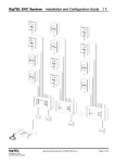
Dimensions in metres
Key
1
measuring point (MP)
2
3
MP hold
land surface datum (LSD)
4
5
water level
depth to water from LSD = 12,86
6
7
depth to water from MP = 13,71
wetted chalk mark
Figure 1 — Water-level measurements using a graduated steel tape
5
BS ISO 21413:2005
4
Water-level measurement using an electric tape
4.1
Purpose
The purpose of this method is to measure the depth to the water surface below a measuring point using the
electric tape method.
Electric tapes fall into two categories:
⎯
Type 1 those that have fixed graduations lacking a suitable frequency (e.g. 1 m graduation) that would
enable readings to be made at a sufficient accuracy without the use of additional graduated measures
(e.g. tapes calibrated in centimetres). Type 1 tapes are referred to as “partially graduated” tapes in the
rest of this clause; and
⎯
Type 2 those with fixed graduations which are spaced at lengths equal to or smaller than the accuracy
required for the readings. Type 2 tapes are referred to as “fully graduated” tapes in the rest of this clause.
4.2
Materials and instruments
The following materials and instruments are required.
4.2.1 Electric tape of various wiring arrangements or configurations, that would include flat parallel or
co-axial conductive wires, graduated in metres and/or centimetres. Electric tapes are commonly mounted on a
hand-cranked supply reel that contains space for the batteries and some device for signalling when the circuit
is closed (Figure 2).
4.2.2
Electric tape calibration and maintenance equipment log book.
4.2.3
Pencil and eraser.
4.2.4
Water-level measurement field form (Tables 2 and 3).
4.2.5
Equipment to gain access to the well (wrenches, crow bars, manhole keys, etc.).
4.2.6
Common household chlorine bleach, and, for measurements made with Type 1, electric tapes.
4.2.7
Steel tape graduated in metres and centimetres.
4.2.8
Spare batteries.
4.3
Data accuracy and limitations
The following data accuracy and limitations apply.
a)
Independent electric tape measurements of static water levels using the same tape should agree within
± 1,0 cm for depths of less than 60 m.
b)
For depths of about 150 m, the maximum difference of independent measurements using the same tape
should agree within ± 3,0 cm.
c)
For depths in the 500 m range, the repeatability of measurements using the same tape should agree
within ± 15 cm (see Reference [2], p. 11).
6
BS ISO 21413:2005
4.4
Advantages and disadvantages
The electric tape method is superior to the graduated steel tape method when
a)
water is dripping into the well or condensing on the inside of casing walls which may make it very difficult
to get a good water mark on the chalked tape,
b)
wells are being pumped and the splashing of the water surface makes chalked measurements virtually
impossible, and
c)
a series of measurements are needed in quick succession, such as in aquifer tests, because the electric
tape does not have to be removed from the well for each reading.
Also, the electric tape method is safer to use in pumping wells because the water is sensed as soon as the
probe reaches the water surface and there is less danger of lowering the tape into the pump impellers.
Electric tape measurements are generally less accurate than are measurements made with graduated steel
tapes. Electric tapes are also harder to keep calibrated than are steel tapes and electric connections need to
be maintained in good order. Also, the insulation around the conductor cables may be severed when being
drawn across sharp edges of metal pipes at the top of a borehole. In addition, the presence of hydrocarbons
on the water surface that may result from oil leaks during drilling operations may coat the sonde, resulting in a
failure to complete the electrical circuit. Finally, a stilling pipe may be required to avoid inaccurate readings
where water is cascading down the borehole during pumping (aquifer) tests.
In general, fully graduated tapes are preferred to partially graduated tapes. Fully graduated tapes are easier to
use and there are fewer opportunities for errors in measurement, particularly when the time intervals between
measurements are small such as during pumping tests.
4.5
Assumptions
Application of the electric tape method assumes
a)
that an established measuring point (MP) exists; and
b)
if the water level is to be referenced to land surface, that the distance between the MP and land-surface
datum (LSD) is known (see the example in Figure 7).
See the technical procedure described in Clause 7 for establishing a permanent MP.
Also, the MP should be clearly marked and described so that all measurements will be taken from the same
point.
If the MP of record cannot be located, the use of data for assessing long-term trends may be compromised. In
such cases, a new MP should be established and the date of change should be indicated on the record sheet.
4.6
Procedures
The following procedures for measuring water levels in a well with an electric tape shall be observed.
a)
Prior to using an electric tape in the field, calibrate it by comparing the total length of the electric tape
against the length of an acceptable steel tape. An acceptable steel tape is one that has a fixed graduation
of a centimetre (or less) and that is maintained in the office for the sole purpose of calibrating electric
tapes. Also, check the accuracy of the position of each 1 m interval metal band to make sure that the
bands have not moved. This is especially important if the electric tape has been used for a long time or
after it has been pulled hard in attempting to free the line. If the field tape fails to meet test criteria, then it
must be removed from service. Records of these tests shall be kept.
7
BS ISO 21413:2005
b)
Before lowering the probe into the well, check the circuitry of the electric tape by dipping the probe into
water and observe if the indicator (needle, light, or buzzer) is operating correctly as the circuit closes.
Note the position the indicator needle deflects during the circuitry check.
c)
Lower the electrode probe slowly into the well until contact with the water surface causes the circuit to
close, activating the indicator (Figure 2). Slightly raise and then lower the electrode again to identify just
where the electrode first comes into contact with the surface of the water. Once the indicator needle
deflects to the point chosen during the circuitry check, place the nail of the index finger on the insulated
wire at the MP.
d)
For fully graduated tapes, partly withdraw the electric tape from the well and record the depth to water to
the nearest centimetre or less if, in the opinion of the observer, the instrumentation is capable of greater
precision. Record in the “DEPTH TO WATER FROM MP” column of the water-level measurements field
form (see the example in Figure 7).
For partially graduated tapes, partly withdraw the electric tape from the well and record the metre mark of
the nearest 1-metre tape band below the MP in the “NEAREST 1-metre TAPE BAND BELOW MP”
column of the water-level measurements field form (see the example in Figure 8). Then measure the
distance from the MP mark on the insulated wire to the nearest 1-metre tape band that is below the MP
mark with a graduated steel tape and record that distance, to the nearest centimetre, in the
“DIFFERENCE BETWEEN MP MARK AND NEAREST 1-metre TAPE BAND BELOW MP” column of the
water-level measurements field form (see the example in Figure 8). The depth to water below MP is then
obtained by adding the distance between the MP mark and the next lowest 1-metre tape band to the
value of the next lowest tape band. Record this number in the “DEPTH TO WATER FROM MP” column of
the water-level measurements field form (see the example in Figure 8).
e)
Apply the MP correction to get the depth to water below or above LSD. If the MP is above land surface,
its height is subtracted from the water level to obtain the depth to water below land surface. If the MP is
below land surface, precede the MP correction value with a minus (-) sign and subtract its height from the
water level to obtain the depth to water below land surface. Subtract the MP correction (Table 2 or
Table 3) from the depth to water from MP (Table 2 or Table 3) and record this number in the “DEPTH TO
WATER CORRECTED FOR LSD” column of the water-level measurements field form (Table 2 or
Table 3). If the water level is above LSD, enter the water level in centimetres above land surface
preceded by a minus sign (−).
f)
Make a check measurement by repeating steps d) through f). If the check measurement does not agree
within the accuracy given in 4.3 under “Data accuracy and limitations”, continue to make check
measurements until the reason for the lack of agreement is determined. If more than two measurements
are taken, the observer shall select the reading considered the most reliable. This reading shall be
recorded to the nearest centimetre.
g)
After completing the well measurement, disinfect the electric tape by pouring a small amount of common
household chlorine bleach or other suitable disinfectant on a clean cloth and then wipe down that part of
the tape that was submerged below the water surface. This will avoid possible contamination of other
wells.
h)
Maintain the tape in good working condition by periodically checking the tape for breaks, kinks, and
possible stretch due to the suspended weight of the tape and the tape weight. Do not let the tape rub
across the top of the casing because the 1-metre metal bands can become displaced; consequently,
placement of the bands should be checked frequently with a steel tape.
8
BS ISO 21413:2005
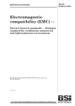
Key
1
light indicator
2
3
reel
casing
4
5
electric cable
electrode(s)
6
water
Figure 2 — Water-level measurements using an electric tape (adapted from Reference [1], Figure 16.12)
9
BS ISO 21413:2005
Because an electric tape will not respond to oil floating on water in a well, the liquid level determined by an
electric tape will be different than that determined by a steel tape, with the difference depending on the
thickness of the oil layer. In cases where this is of concern, a miniature float-driven switch can be put on a
two-conductor electric tape that will allow detection of the oil surface.
All calibration and maintenance data associated with the electric tape being used shall be recorded in its
calibration and maintenance equipment log book. All data shall be recorded in the water-level measurements
field form (see the example in Figure 6) to the appropriate accuracy (4.3) for the depth being measured.
In the event no water is encountered in the well, this shall be duly noted under “REMARKS” on the field form,
along with the distance between the MP and the bottom of the well.
5
Water-level measurement using an air line
5.1
Purpose
The purpose of this method is to measure the depth to the water surface below a measuring point using a
submerged air line.
5.2
Materials and instruments
The following materials and instruments are required.
5.2.1 Seamless copper tubing, brass tubing, or galvanized pipe, preferably 3 mm to 6 mm in diameter
with a suitable pipe tee for connecting an altitude or pressure gauge.
Flexible plastic tubing can also be used, but is less desirable.
5.2.2
Altitude or pressure gauge.
5.2.3
Tyre valve stem and tyre pump.
5.2.4
Small open end wrench.
5.2.5
Wire or electrician’s tape.
5.2.6
Steel tape graduated in metres and centimetres.
5.2.7
Blue carpenter's chalk.
5.2.8
Clean rag.
5.2.9
Field notebook, pencil and eraser.
5.2.10 Water-level measurements field form (see the example in Figure 9).
5.3
Data accuracy and limitations
The following data accuracy and limitations apply.
a)
Water-level measurements using an altitude gauge should be accurate to within 3 cm.
b)
Water-level measurements using a pressure gauge are more approximate and should not be considered
accurate to more than 30 cm.
10
BS ISO 21413:2005
c)
5.4
As in all pressure-dependent methods, fluid density should be considered when measuring water levels
by the air-line method, because the conversion constant of 0,102 m of water per kilopascal (referenced
later in 5.6) is valid only for distilled water at 20 °C. Fluid density is affected primarily by the temperature
and dissolved solids content of the water. An example of correcting a water level measured by an air line
for temperature and dissolved solids content is given in Annex B. However, because the equipment
required to measure the temperature and/or dissolved solids content of the groundwater is not always
readily available, the corrections described in Annex B are not required for the purposes of this
International Standard, though the practitioner shall note on the water-level field form (see the example in
Figure 10) whether or not any such corrections were applied.
Advantages and disadvantages
The air-line method is especially useful in pumped wells where water turbulence may preclude using a more
precise method. The method can be used while the well is being pumped, when splashing of water renders
the wetted tape method useless. Bends or spirals in the air line do not influence the accuracy of this method
as long as the position of the tubing is not appreciably changed. However, the method is less accurate than
the wetted tape or the electric tape methods and requires time to install the air line and equipment.
5.5
Assumptions
The following assumptions apply in the use of the air-line method.
a)
An established measuring point (MP) exists. See the technical procedure described in Clause 7 for
establishing an MP.
b)
The MP is clearly marked and described so that all measurements will be taken from the same point.
5.6
Procedures
Figure 3 shows a typical installation for measuring water levels by the air-line method.
The following procedures for measuring water levels in a well with an air line shall be observed.
a)
Install an air-line pipe or tube in the well. The air line can be installed by either lowering it into the annular
space between the pump column and casing after the pump has been installed in the well, or by securing
it to sections of the pump and pump column with wire or tape as it is lowered into the well.
b)
The air line shall be extended far enough below the water level such that the lower end remains
submerged during pumping of the well.
c)
Attach a pipe tee to the top end of the air line. On the opposite end of the pipe tee, attach a tyre valve
stem.
d)
Connect an altitude gauge that reads in meters, or a pressure gauge that reads pressure in kilopascals
(kPa), to the fitting on top of the pipe tee with a wrench. If an altitude gauge is used, read the gauge to the
nearest centimetre. For pressure gauges with kilopascal (kPa) units, read the gauge to the nearest
kilopascal (kPa) and multiply by 0,102 m/kPa to convert to meters of water.
e)
Connect a tyre pump to the tire valve stem fitting on the pipe tee.
f)
As the water level in the well changes, h and d (Figure 3) must change in a manner such that their sum
remains the same. Their sum is a constant (k), which is determined at the same time as a simultaneous
wetted-steel tape and air gauge measurement is made.
11
BS ISO 21413:2005
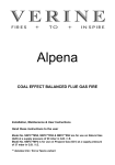
Key
1
2
3
4
5
6
7
altitude a or pressure gauge b
tyre pump
pipe tee
well casing
water level
air line
pump line or column
a
For the altitude gauge:
d = k ⋅ h,
where
d
is the measured depth to water level, in metres;
h
is the height of water displaced from the air line, in metres; and
For the pressure gauge:
d = k ⋅(1,04p) and h = 0,104p,
where
p
is the pressure reading in kilopascals; and
d, h and k are in metres.
b
Figure 3 — Typical installation for measuring water levels by the air-line method and relation of
measured depth to water level, height of water displaced from air line, and depth to bottom of air line
12
BS ISO 21413:2005
g)
To calibrate the air line and gauge, make an initial depth to water-level measurement (d) with a
wetted-steel tape, and an initial air gauge reading (h). Add d and h to determine the constant value for k.
Use a tyre pump to pump compressed air into the air line until all the water is expelled from the line. Once
all water is displaced from the air line, record the maximum gauge reading.
EXAMPLE 1
Using an altitude gauge. The initial measured depth to the water level, d, is 7,88 m; the initial altitude
gauge reading, h, is 23,02 m. Then the constant k = 7,88 m + 23,02 m = 30,90 m (see the example in Figure 9).
EXAMPLE 2
Using a pressure gauge. The initial measured depth to the water level, d, is 26,17 m; the initial pressure
gauge reading, h, is 190 kPa. Then the constant k = 26,17 m + (190 kPa × 0,102 m/kPa) = 26,17 m + 19,38 m = 45,55 m
(see the example in Figure 10).
h)
Calibrate the air line and gauge as indicated in g) above.
i)
To measure the water-level depth in a well with an air line, subsequent air line readings are subtracted
from the constant k to determine the depth to the water level below the MP. Use a tyre pump to pump
compressed air into the air line until all the water is expelled from the line, and record the maximum
gauge reading.
EXAMPLE 3
Depth to the water level in a well using an altitude gauge with a constant k of 30,90 m. During a later
pumping period, the maximum altitude gauge h reads 15,24 m; therefore, the water level,
d = 30,90 m − 15,24 m = 15,66 m
(see the example in Figure 9).
EXAMPLE 4
Depth to the water level in a well using a pressure gauge with a constant k of 45,55 m. During a later
pumping period, the maximum pressure gauge h reads 122 kPa; therefore, the water level,
d = 45,55 m − (122 kPa × 0,102 m/kPa) = 45,55 m − 12,44 m = 33,11 m (see the example in Figure 10).
j)
Measure the water-level depth as indicated in i) above.
k)
Apply the MP correction to get the depth to water below or above land-surface datum.
l)
Record water-level data in the field notebook and on the water-level measurements field form (Table 4 or
Table 5).
6
Water-level measurement in a flowing well
6.1
Purpose
The purpose of this method is to measure low-pressure or high-pressure water-level heads in flowing wells.
6.2
Materials and instruments
The following materials and instruments are required.
6.2.1
Low-pressure head measurements
6.2.1.1
Transparent plastic tubing, of suitable length and diameter.
6.2.1.2
Ladder, if pressure head is more than 2 m to 3 m.
6.2.1.3
Hose clamps.
6.2.1.4
Measuring scale.
6.2.1.5
Pencil and eraser.
13
BS ISO 21413:2005
6.2.1.6
Calibration and maintenance log book.
6.2.1.7
Water-level measurements field form (see the example in Figure 11).
6.2.2
High-pressure head measurements
6.2.2.1
Flexible hose with a 3-way valve.
6.2.2.2
Hose clamps.
6.2.2.3
Altitude or pressure gauge.
6.2.2.4
Small open-end wrench.
6.2.2.5
Soil-pipe test plug, also known as a sanitary seal, available from most plumbing-supply stores in
sizes that will fit 5 cm to 25 cm diameter pipes.
Soil-pipe test plugs consist of a length of small-diameter pipe, generally less than 3 cm, surrounded by a
rubber packer. The packer can be expanded by an attached wing nut to fit tightly against the inside of the well
casing or discharge pipe. The small-diameter pipe is threaded so that it can be attached to a valve, hose, or
altitude/pressure gauge.
6.2.2.6
Pencil and eraser.
6.2.2.7
Calibration and maintenance log book.
6.2.2.8
Water-level measurement field form (see the example in Figure 11).
6.3
Data accuracy and limitations
The following data accuracy and limitations apply.
a)
Low-pressure head measurements can be measured to an accuracy of 3,0 cm.
b)
High-pressure head measurements using a pressure-gauge are probably not accurate to within less than
3,0 cm, although the measurements themselves can be read at finer resolutions.
c)
The pressure in the well shall not exceed the limit of the altitude/pressure gauge. Pressure gauges are
generally most accurate in the middle third of the gauge range.
d)
The measuring gauge shall not be connected to a well that uses a booster pump in the system, because
the pump could start automatically and the resulting pressure surge may ruin the gauge.
e)
When a flowing well is closed or opened by a valve or test plug, it should be done gradually. If pressure is
applied or released suddenly, the well could be permanently damaged by the “water-hammer effect” with
subsequent caving of the aquifer material, breakage of the well casing, or damage to the distribution lines
or gauges. To reduce the possibility of a water-hammer effect, a pressure-snubber should be installed
ahead of the altitude/pressure gauge.
f)
Ideally, all flow from the well should be shut down so that a static water-level measurement can be made.
However, because of well owner objections or system leaks, this is not always possible. If the well does
not have a shut-down valve, it can be shut-in by installing a soil-pipe test plug on the well or discharge
line.
g)
If a well has to be shut down, the time required to reach static pressure after shut down may range from
hours to days. Since it may be impractical or impossible to reach true static conditions, record the
shut-down time for each gauge reading. During return visits to a particular well, it is desirable to duplicate
the previously used shut-in time before making a altitude/pressure gauge reading.
14
BS ISO 21413:2005
6.4
Advantages and disadvantages
Low-pressure head measurements are simpler, faster, safer, and are more accurate than high-pressure head
measurements, but are impractical for wells with heads greater than 2 m above land surface.
High-pressure head measurements can be made at wells with heads greater than 2 m above land surface, but
the altitude/pressure gauges required for such measurements are delicate, easily broken, and subject to
erroneous readings if dropped or mistreated.
SAFETY PRECAUTIONS — The soil-test plugs used in high-pressure head measurements may present
a safety risk, as these devices could slip from the casing and become projectiles.
6.5
Assumptions
The following assumptions apply when measuring water levels in a flowing well.
a)
An established measuring point (MP) exists. See the technical procedure in Clause 7 for establishing an
MP.
b)
The altitude/pressure gauges have been calibrated with a dead-weight tester.
c)
A log book, containing all the calibration and maintenance records, is available for each altitude/pressure
gauge.
6.6
Procedures
6.6.1
Low-pressure head measurement (direct measurement)
Use the following procedure.
a)
Connect a short length of transparent plastic tubing tightly to the well with hose clamps.
b)
Raise the free end of the tubing until the flow stops.
c)
Rest the measuring scale on the measuring point (MP).
d)
Read the water level directly by placing the hose against the measuring scale.
e)
Apply the MP correction to get the depth to water above land-surface datum (LSD).
f)
Repeat steps b) through e) for a second check reading. If the check measurement does not agree within
the accuracy given in 6.3 under “Data accuracy and limitations” continue to make check measurements
until the reason for the lack of agreement is determined. If more than two measurements are taken, the
observer shall select the reading considered the most reliable.
6.6.2
High-pressure head measurement (indirect measurement)
Use the following procedure.
a)
Make sure that all well valves are closed except the one to the altitude/pressure gauge. This will prevent
use of the well during the measurement period and assure an accurate water-level reading. Record the
original position of each valve that is closed (full open, half open, closed, etc.), so that the well can be
restored to its original operating condition.
b)
Connect a flexible hose with a 3-way valve to the well with hose clamps using the soil-pipe test plug or
appropriate plumbing fittings.
15
BS ISO 21413:2005
c)
Select a gauge where the water pressure in the well will fall in the middle third of the gauge range. It is
suggested that, if in doubt, use a pressure gauge with at least a 500 kPa range to make an initial
measurement, then select the gauge with the proper range for more accurate measurements.
d)
Attach the altitude/pressure gauge to one of the two "open" valve positions using a wrench. Do not tighten
or loosen the gauge by twisting the case because the strain will disturb the calibration and give erroneous
readings.
e)
Bleed air from the hose, using the other “open” valve position.
f)
Open the altitude/pressure gauge valve slowly to reduce the risk of damage by the “water-hammer effect”
to the well, distribution lines and gauges. Once the needle stops moving, tap the glass face of the gauge
lightly with a finger to make sure that the needle is not stuck.
g)
Make sure that the well is not being used by checking to see that there are no fluctuations in pressure.
h)
Hold the altitude/pressure gauge in a vertical position, with the centre of the gauge at the exact height of
the MP. If using an altitude gauge, read the gauge to the nearest centimetre. For pressure gauges with
kilopascal (kPa) units, read the gauge to the nearest kilopascal (kPa) and multiply by 0,102 to convert to
metres of water.
i)
Apply the MP correction to get the depth to water above LSD.
j)
Shut off the well pressure and repeat steps e) through i) for a second check reading. If the check
measurement does not agree within the accuracy given in 6.3 under “Data accuracy and limitations”
continue to make check measurements until the reason for the lack of agreement is determined. If more
than two measurements are taken, the observer shall select the reading considered the most reliable.
k)
Record the identification number of the altitude/pressure gauge with each water-level measurement so
that the reading can be back referenced to the calibration record, if necessary.
All calibration and maintenance data for the well shall be recorded in the log book. All water-level data shall be
recorded on the water-level measurements field form (see the example in Figure 11).
7
Establishing a permanent measuring point
7.1
Purpose
The purpose of this method is to establish a permanent reference point from which all water levels are
measured in a particular well.
7.2
Materials and instruments
The following materials and instruments are required.
7.2.1 Form for recording the information required to locate and document the establishment of a
permanent measuring point (see Reference [8] as an example).
7.2.2
Steel tape graduated in metres and centimetres.
7.2.3
Steel tape calibration and maintenance equipment log book.
7.2.4
Field notebook.
7.2.5
Pencil and eraser.
7.2.6
Spray paint or road chalk, bright colour.
16
BS ISO 21413:2005
7.2.7
7.3
Two wrenches with adjustable jaws, for removing the well cap.
Data accuracy and limitations
The accuracy with which the measuring point (MP) measurement is established should be the same as that
established for the water-level measurement; that is, if water levels are measured to the nearest centimetre,
then the MP should be established to an accuracy of 0,01 m.
7.4
Assumptions
For comparability, water-level measurements shall be referenced to the same datum (elevation). Land surface
datum (LSD) at the well is an arbitrary plane chosen to be approximately equivalent to the average altitude of
the ground around the well. Because the LSD around a well may change over time, the distance between the
MP and the LSD should be checked periodically. Also, measuring points change from time to time, especially
on private wells.
7.5
Procedure
Use the following procedure
a)
The MP shall be as permanent as possible, clearly defined, marked, and easily located.
b)
The top of the well casing, which provides the most convenient location for measuring a water level in a
well, should be designated as the MP and should be measured in reference to land surface datum (LSD).
c)
The MP should be measured in reference to land surface datum (LSD) and at a point on the well
convenient for measuring water levels (most often at the top of the well casing).
d)
Clearly mark the MP with an arrow sprayed with a bright coloured paint or chalk.
e)
Measure the height of the MP above or below LSD (Figure 5) and record it on the ground-water site
inventory form. Values for measuring points below land surface [Figure 5 b)] shall be preceded by a
minus sign (−). Also record the date the MP was established and a detailed description of the MP. It is
highly recommended that the MP and LSD be “surveyed-in” to a national geodesic reference point. If so,
then the accuracy of the surveyed altitude should be estimated and recorded in the well file.
f)
Establish at least one clearly marked reference point (RP) somewhere near the well. For example, a lag
bolt set in a telephone pole (Figure 5). The RP is an arbitrary datum established by permanent marks,
and is used to check the MP or to re-establish a measuring point should the original MP be destroyed or
changed.
g)
Make a detailed sketch of the MP and the RP on the groundwater site inventory form and, if possible,
take a photograph. Clearly identify the MP and RP on the developed photograph. Also, all calibration and
maintenance data associated with the steel tape being used are recorded in its calibration and
maintenance equipment log book. MP data are recorded in a field notebook and on the ground-water site
inventory form.
17
BS ISO 21413:2005
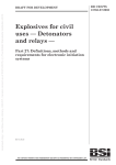
Key
1
water level
2
3
transparent flexible tubing
soil pipe test plug
4
5
measuring scale
well casing
6
7
measuring point (MP)
pressure gauge
8
9
flexible tubing
3-way valve
10 soil pipe test plug
11 well casing
12 land surface
Figure 4 — Water-level measurement in a flowing well
18
BS ISO 21413:2005
a)
MP above LSD — Subtract MP correction to correct this water level to LSD (5,50 − 1,50 = 4,0)
b)
MP below LSD — Subtract MP correction to correct this water level to LSD [5,20 − (−1,20) = 6,40]
Key
1
2
3
4
5
measuring point (MP)
reference point (RP)
land-surface datum (LSD)
lag bolt
water level
a
MP correction.
Figure 5 — Relation of measuring point, above or below the land surface datum,
reference point, and water level
19
BS ISO 21413:2005
WATER-LEVEL MEASUREMENTS (Field)
WELL NO.
NHW 258__
SITE NAME AND LOCATION
(include latitude/longitude if
feasible)
Town of New Shoreham, Block Island, Rhode Island
MP DESCRIPTION
Top inside edge of stainless steel casing, 0,85 m above land surface
datum
MISCELLANEOUS NOTES
No adjustment made for several centimetres of oil floating on water
surface
DATE
TIME OF
MEASUREMENT
MP HOLD
WETTED
CHALK
MARK
DEPTH TO
DEPTH TO
WATER FROM WATER FROM
MP
LSD
REMARKS
(include name of
observer)
Local time
YYYY-MM-DD
(GMT)
m
m
m
m
2002-08-29
14:45
15,00
1,29
13,71
12,86
(18:45)
Measured by Lansen
Ramsbey
Figure 6 — Example of field data sheet for measurement of water levels with a graduated steel tape
20
BS ISO 21413:2005
WATER-LEVEL MEASUREMENTS (Field)
WELL NO. ____________
SITE NAME AND LOCATION
(include latitude/longitude if
feasible)
Top inside edge of stainless steel casing, 1,50 m above land surface
datum
MP DESCRIPTION
DATE
YYYY-MM-DD
TIME OF
MEASUREMENT
Local time
(GMT)
DEPTH TO WATER
FROM MP
DEPTH TO WATER
FROM LSD
m
m
8,15
6,65
REMARKS
(include name of observer)
12:31
2002-04-16
Measured by Mary Smith
(17:31)
Figure 7 — Example of field data sheet for measurement of water levels
with a fully graduated electric tape
21
BS ISO 21413:2005
WATER-LEVEL MEASUREMENTS (Field)
WELL NO. ____________
SITE NAME AND LOCATION
(include latitude/longitude if
feasible)
Top inside edge of stainless steel casing, 1,50 m above land surface
datum
MP DESCRIPTION
DATE
YYYY-MM-DD
NEAREST
DIFFERENCE
1-metre
BETWEEN
TIME OF
TAPE
MP MARK AND
MEASUREMENT
BAND
NEAREST 1-metre
BELOW
TAPE BAND
MP
BELOW MP
Local time
(GMT)
DEPTH TO
WATER FROM
MP
DEPTH TO
WATER FROM
LSD
m
m
m
m
9,00
0,85
8,15
6,65
11:09
2002-04-16
(16:09)
REMARKS
(include name of observer)
Measured by Mary
Smith
Figure 8 — Example of field data sheet for measurement of water levels
with a partially graduated electric tape
22
BS ISO 21413:2005
WATER-LEVEL MEASUREMENTS (Field)
WELL NO. ____________
SITE NAME / LOCATION
(include latitude/longitude if
feasible)
MP DESCRIPTION
Top inside edge of steel casing, red arrow, north side, 0,50 m above
land surface datum.
Altitude gauge calibration data:
Initial wetted steel tape water level, d, is 7,88 m;
initial altitude gauge reading, h, is 23,02 m;
constant k = d + h = 7,88 m + 23,02 m = 30,90 m.
DATE
YYYY-MM-DD
ALTITUDE
GAUGE
READING
DEPTH TO
WATER FROM
MP
DEPTH TO
WATER FROM
LSD
(k)
(h)
(d)
(d − MP)
m
m
m
m
30,90
23,02
7,88
7,38
Altitude gauge calibrated
by John Smith
30,90
15,24
15,66
15,16
First air line water
measurement, John Smith
ALTITUDE
GAUGE
TIME OF
MEASUREMENT CONSTANT
Local time
REMARKS
(include name of observer)
(GMT)
12:02
2002-05-31
(17:02)
12:12
2002-06-01
(17:12)
Figure 9 — Example of field data sheet for measurement of water levels
with an air line using an altitude gauge
23
BS ISO 21413:2005
WATER-LEVEL MEASUREMENTS (Field)
WELL NO. ____________
SITE NAME / LOCATION
(include latitude/longitude if
feasible)
MP DESCRIPTION
Top inside edge of steel casing, red arrow, south side, 1,00 m above
land surface datum.
Pressure gauge calibration data:
Initial wetted steel tape water level, d, is 26,17 m;
initial pressure gauge reading, h, is 190 kilopascals (kPa);
constant k = d + h = 26,17 m + 19,38 m = 45,55 m.
Pressure gauge reading h (in metres) is calculated as pressure gauge
reading (in kPa) × 0,102 (kPa/m).
DATE
YYYY-MM-DD
PRESSURE
GAUGE
READING
DEPTH TO
WATER
FROM MP
DEPTH TO
WATER FROM
LSD
(h)
(d)
(d − MP)
m
m
m
m
45,55
19,38
(190 kPa)
26,17
25,17
Pressure gauge calibrated
by John Smith
45,55
12,44
(122 kPa)
33,11
32,11
First air line waterlevel measurement, John
Smith
PRESSURE
GAUGE
TIME OF
MEASUREMENT CONSTANT
(k)
Local time
(GMT)
14:50
2002–05–31
(19:50)
14:47
2002–06–01
(19:47)
REMARKS
(include name of observer)
Figure 10 — Example of field data sheet for measurement of water levels
with an air line using a pressure gauge
24
BS ISO 21413:2005
WATER-LEVEL MEASUREMENTS (Field)
WELL NO. ____________
SITE NAME / LOCATION
Crescent Lake, Flagler Co., Florida
(include latitude/longitude if
feasible)
MP DESCRIPTION
DATE
YYYY-MM-DD
Top of casing at chiselled mark; 1,12 m above land surface datum.
Pressure head (water level) reading (in metres) is calculated as
pressure gauge reading (in kPa) × 0,410 2.
TIME OF
MEASUREMENT
Local time
(GMT)
PRESSURE HEAD PRESSURE HEAD
(WATER LEVEL)
(WATER LEVEL)
ABOVE MP
ABOVE LSD
m
m
1,06
2,18
REMARKS
(include name of observer)
10:34
2001-06-09
Pressure gauge # 7, measured by GB Smith
(14:34)
Figure 11 — Example of field data sheet for measurement of pressure head (water level)
in a flowing well
25
BS ISO 21413:2005
Annex A
(informative)
Corrections for water levels measured in deep wells by steel tapes
subject to temperature changes and tape stretch
In measuring water levels in deep wells, practitioners may wish to consider errors introduced from the effects
of thermal expansion and/or stretch of the metal tape produced by the suspended weight of the tape and
attached plumb bob. While such errors are negligible for many water-level measurements, they may become
appreciable for measurements in deep wells, that is, for wells exceeding 300 m in depth (see Reference [2],
p. 3). The corrections described below are not required for the purposes of this International Standard, but
rather to provide the practitioner a means of evaluating the potential magnitude of such errors.
The equations used to estimate the changes in length of a metal tape resulting from thermal expansion and
stretch are given in Equations (A.1) and (A.2), respectively, from Reference [2] as
CT = L⋅E(Ta − 20 °C)
(A.1)
CS = (Le2m⋅S/2) + P⋅LeS
(A.2)
and
where
CT is the thermal correction, in metres (m);
CS is the stretch correction, in metres (m);
L
is the measured depth to water, in metres (m);
E
is the coefficient of thermal expansion of the steel tape, in metres per metre per degree Celsius
difference between the average temperature in the well and 20 °C (m/m per °C);
Ta is the average temperature in the well from land surface to water level, in degrees Celsius (°C);
Le is the length of suspended tape corrected for thermal expansion, in metres (m);
26
m
is the mass of tape, in kilograms (kg), per metre of tape;
S
is the coefficient of stretch, in metres per metre per kilogram (m/m per kg); and
P
is the mass of plumb bob, in kilograms (usually 0,10 kg to 0,30 kg).
BS ISO 21413:2005
EXAMPLE
The following example illustrates the effects of thermal expansion and stretch on a steel tape used to
measure water levels in a deep well.
Given:
L = 515,00 m
E = 1,13 × 10⁻⁵ m/m per °C
(from Reference [2])
Ta = 30 °C
m = 0,003 6 kg
(from Reference [2])
S = 3,85 × 10⁻⁵ m/m per kg
(from Reference [2])
P = 0,20 kg
Correction for thermal expansion:
CT = L⋅E(Ta − 20 °C) = (515,00 m)(1,13 × 10⁻⁵ m/m per °C)(30 °C − 20 °C) = 0,06 m
then
Le = 515,00 m − 0,06 m = 514,94 m (rounded to the nearest centimetre)
Correction for stretch:
CS
= (Le2mS/2) + PLeS
= [(514,94 m)2(0,003 6 kg)(3,85 × 10⁻⁵ m/m per kg)/2)] + [(0,20 kg)(514,94 m)(3,85 × 10⁻⁵ m/m per kg)]
= 0,02 m (rounded to the nearest centimetre)
then
corrected depth = Le − stretch correction = 514,94 m − 0,02 m = 514,92 m
27
BS ISO 21413:2005
Annex B
(informative)
Corrections for water levels measured in wells with the air-line method
As in all pressure-dependent methods, fluid density should be considered when measuring water levels by the
air-line method. Fluid density is affected primarily by temperature and, to a lesser extent, by the concentration
of dissolved solids. The density of water at 20 °C is 0,998 23 g/ml. At this density, 0,102 m of water can be
associated with each kilopascal of measured pressure. However, water with temperatures greater than or less
than 20 °C would have proportionately smaller or greater densities, respectively, with proportionately greater
or smaller conversion factors. A table (Table B.1), quantifying the change in density of distilled water over a
wide temperature range, is shown below.
Table B.1 — Density of pure water, free from air
Temperature
Density of pure water, free
from air
Temperature
°C
g/ml
°C
g/ml
0
0,999 87
45
0,990 25
3,98
1,000 00
50
0,988 07
5
0,999 99
55
0,985 73
10
0,999 73
60
0,983 24
15
0,999 13
65
0,980 59
18
0,998 62
70
0,977 81
20
0,998 23
75
0,974 89
25
0,997 07
80
0,971 83
30
0,995 67
85
0,968 65
35
0,994 06
90
0,965 34
38
0,992 99
95
0,961 92
40
0,992 24
100
0,958 38
T
Table modified from Reference [4].
28
T
Density of pure water, free
from air
BS ISO 21413:2005
To illustrate the use of the Table B.1 in correcting water-level measurements for temperature in air lines,
consider Example 2, which was previously described in 5.6 and shown in Table 5. If, in that example, the
water in the air line had some temperature other than 20 °C, say 60 °C, then the conversion factor, Cc, used to
convert the pressure reading in kilopascals to metres of water would be recalculated as
Cc = 0,102 m/kPa × (0,998 23 g/ml)/(0,983 24 g/ml) = 0,103 6 m/kPa
and
initial h = 0,103 6 m/kPa × 190 kPa = 19,68 m,
and (from Table 5),
k = 19,68 + 26,17 = 45,85 m
then, the corrected depth to water would be calculated as
d=k−h
= 45,85 m − (0,103 6 m/kPa × 122 kPa)
= 33,21 m (versus an uncorrected depth of 33,11 m from Table 5).
In moderate concentrations, the effect of dissolved solids on fluid density is at least one order of magnitude
less than that of temperature. For example, for dissolved solids having a specific gravity of 2,5 (water taken as
unity), calculations show that the density of water having a dissolved solids concentration of 100 mg/l would
be 1,000 06; water having a dissolved solids concentration of 200 mg/l would have a density of 1,000 12; and
water having a dissolved solids concentration of 1 000 mg/l would have a density of 1,000 6.
29
BS ISO 21413:2005
Bibliography
[1]
DRISCOLL, F.G. Groundwater and wells (2nd ed.), Johnson Division, St. Paul, Minnesota, 1986,
1 089 pp
[2]
GARBER, M.S., and Koopman, F.C. Methods of measuring water levels in deep wells. U.S. Geological
Survey TWRI, Book 8, Chapter A1; Washington, U.S. Government Printing Office, 1968, 23 pp
[3]
Ground water and wells, A reference book for the water-well industry (1st ed., 4th printing), Johnson
Division, UPO Inc., Saint Paul, Minnesota, 1975, pp. 90-91
[4]
Handbook of Chemistry and Physics, 56 Edition, CRC Press, (Weast, Robert C., ed.),1975-76
[5]
HEATH, Ralph C. Basic ground-water hydrology. Water Supply Paper 2220, Washington, U. S.
Government Printing Office, 1983
[6]
LOMAN, S.W. Measurement of ground-water levels by air-line method, U.S. Geological Survey Water
Resources Bulletin, November 1953: Washington D.C., 1953, pp. 97-99
[7]
U.S. Office of Water Data Coordination.— National handbook of recommended methods for
water-data acquisition. Office of Water Data Coordination, Geological Survey, U.S. Department of the
Interior, Reston, Va., Chapter 2, 1977, pp. 1-149
[8]
U.S. Geological Survey. National water information system user's manual, ground-water site inventory
system: U.S. Geological Survey Open-File Report 89-587, 2, Chapter 4, 1990
[9]
W INNER, M.D., Jr. Ground-water data collection and processing procedures: U.S. Geological Survey,
Louisiana District, 1969 (unpublished), 44 pp
30
th
blank
BS ISO
21413:2005
BSI — British Standards Institution
BSI is the independent national body responsible for preparing
British Standards. It presents the UK view on standards in Europe and at the
international level. It is incorporated by Royal Charter.
Revisions
British Standards are updated by amendment or revision. Users of
British Standards should make sure that they possess the latest amendments or
editions.
It is the constant aim of BSI to improve the quality of our products and services.
We would be grateful if anyone finding an inaccuracy or ambiguity while using
this British Standard would inform the Secretary of the technical committee
responsible, the identity of which can be found on the inside front cover.
Tel: +44 (0)20 8996 9000. Fax: +44 (0)20 8996 7400.
BSI offers members an individual updating service called PLUS which ensures
that subscribers automatically receive the latest editions of standards.
Buying standards
Orders for all BSI, international and foreign standards publications should be
addressed to Customer Services. Tel: +44 (0)20 8996 9001.
Fax: +44 (0)20 8996 7001. Email: [email protected]. Standards are also
available from the BSI website at http://www.bsi-global.com.
In response to orders for international standards, it is BSI policy to supply the
BSI implementation of those that have been published as British Standards,
unless otherwise requested.
Information on standards
BSI provides a wide range of information on national, European and
international standards through its Library and its Technical Help to Exporters
Service. Various BSI electronic information services are also available which give
details on all its products and services. Contact the Information Centre.
Tel: +44 (0)20 8996 7111. Fax: +44 (0)20 8996 7048. Email: [email protected].
Subscribing members of BSI are kept up to date with standards developments
and receive substantial discounts on the purchase price of standards. For details
of these and other benefits contact Membership Administration.
Tel: +44 (0)20 8996 7002. Fax: +44 (0)20 8996 7001.
Email: [email protected].
Information regarding online access to British Standards via British Standards
Online can be found at http://www.bsi-global.com/bsonline.
Further information about BSI is available on the BSI website at
http://www.bsi-global.com.
Copyright
Copyright subsists in all BSI publications. BSI also holds the copyright, in the
UK, of the publications of the international standardization bodies. Except as
permitted under the Copyright, Designs and Patents Act 1988 no extract may be
reproduced, stored in a retrieval system or transmitted in any form or by any
means – electronic, photocopying, recording or otherwise – without prior written
permission from BSI.
BSI
389 Chiswick High Road
London
W4 4AL
This does not preclude the free use, in the course of implementing the standard,
of necessary details such as symbols, and size, type or grade designations. If these
details are to be used for any other purpose than implementation then the prior
written permission of BSI must be obtained.
Details and advice can be obtained from the Copyright & Licensing Manager.
Tel: +44 (0)20 8996 7070. Fax: +44 (0)20 8996 7553.
Email: [email protected].