1
German
English
Copyright 2004 Access Music GmbH. All rights reserved.
Virus Classic user manual in English and German.
This manual, as well as the software and hardware described in it, is furnished under license and may be used
or copied only in accordance with the terms of such license. The content of this manual is furnished for informational use only, is subject to change without notice
and should not construed as a commitment by Access
Music GmbH. Access Music GmbH assumes no responsibility or liability for any errors or inaccuracies that may
appear in this book.
Except as permitted by such license, no part of this publication may be reproduced, stored in a retrieval system,
or transmitted in any form or by any means, electronic,
mechanical, recording, or otherwise without the prior
written permission of Access Music GmbH.
Virus is a trademark of Access Music GmbH. All other
trademarks contained herein are the property of their respective owners. All features and specifications subject
to change without notice.
Visit our website here: www.access-music.de
Table of contents
> PROLOGUE
Important Safety Remarks
!9
12
> INTRODUCTION
The Amplifier Envelope
The First Filter
Filter Modulation
The Saturation Stage
The Second Filter
Filter Routing
The First Oscillator
The Second Oscillator
The Mixer Section
The LFOs
LFO 1
LFO 2
Volume and Panorama Position
Velocity
Unison Mode
The Chorus/Flanger Effect
The Delay Effect
More to Come
15
18
20
21
23
24
26
28
29
31
32
33
35
36
37
37
38
39
40
> CONCEPT AND OPERATION
Operating Modes
The Multi-Single Mode
Edit Buffers
41
41
42
43
> HANDLING
Parameter Selection and Data Entry
Knob Modes
Display of values
45
45
47
48
> ALL ABOUT THE MEMORY
Store
Compare
Store To Flash
49
49
50
51
> ABOUT TIME ...
Master Clock and Midi-Clock
The Mod Matrix and Soft Knob
The Virus’ Soft Knobs
53
53
54
55
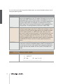
> THE EFFECTS SECTION
Audio Inputs
Osc Volume and Input
Input Level Indicator
57
57
59
59
> INTERNAL AUDIO ROUTING
Aux Buses
The Audio Outputs
61
61
62
> ADDITIONAL FUNCTIONS
Panic Function
Audition function
Reset Function
63
63
63
64
VIRUS CLASSIC MANUAL
Table of Contents
5
> THE PARAMETERS
Front Panel Parameters
LFO 1 – Panel
LFO 1 – Edit Menu
LFO 2 - Panel
LFO 2 Edit Menu
LFO 3 Edit Menu
Oscillator 1- Front Panel
Oscillator 2 – Front Panel
Oscillator 1 Edit Menu
Oscillator-2 Edit Menu
Oscillator-3 Edit Menu
SubOscillator Edit Menu
Osc Mixer Edit-Menu
Mixer
Filters – Front Panel
Filter Edit Menu
Amplifier
Main Edit Menu (Common)
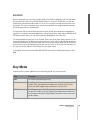
Key Mode
Unison Mode
Assign
Velocity
6
65
65
66
67
69
70
70
72
73
74
74
76
77
77
78
80
84
87
88
89
92
93
94
> WITHIN THE CONFIG-MENU
Common
Arpeggiator
Soft Knob 1/2
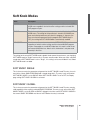
Soft Knob Modes
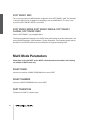
Multi Mode Parameters
97
97
98
100
101
102
> THE EFFECTS MENU
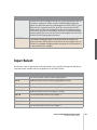
Input
Input Mode
Input Select
Envelope Follower
Ring Modulator
Vocoder
Distortion
Analog Boost
107
107
108
109
110
111
112
112
113
Phaser
Chorus
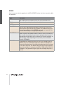
Delay And Reverb
Delay Specific Parameters
Reverb Specific Parameters
114
115
116
119
121
> GLOBAL AND SYSTEM PARAMETERS
System
Random Patch Generator
Categories
125
130
133
134
> PURE TUNING
Pure tuning the Virus
Theory
137
137
139
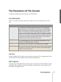
> THE VOCODER OF THE VIRUS
The Parameters Of The Vocoder
Notes About The Vocoder
141
143
146
> THE VIRUS AND SEQUENCERS
Parameter Control via MIDI
Organisational Information
Handling MIDI Parameter Control
Adaptive Parameter Smoothing
Parameter Control Insides
DUMP: The Sound in the Song
149
149
149
151
151
153
154
> TIPS AND TRICKS
All About Inputs
About The Delay/Reverb
The Virus as an Effect Device
Envelope Follower
Oscillators
Filters
Saturation - Adding Grit and Dirt
LFOs
Arpeggiator
MIDI
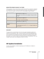
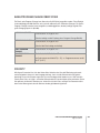
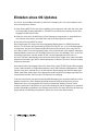
OS Update Installation
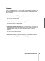
Support
157
158
159
160
160
161
163
164
165
167
168
169
172
> APPENDIX
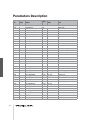
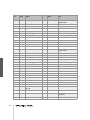
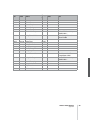
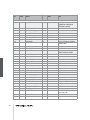
System Exclusive Data
Parameters Description
Multi Dump Table
Classes
Mod Matrix Sources
Mod Matrix Destinations
Soft Knob Knobs Destinations
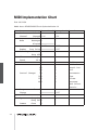
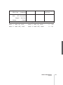
MIDI Implementation Chart
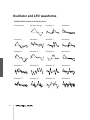
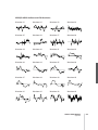
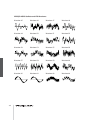
Oscillator and LFO waveforms
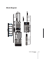
Block Diagram
351
351
358
369
371
374
374
375
376
378
381
> LEGAL STUFF
FCC Information (U.S.A)
FCC Information (CANADA)
Other Standards (Rest of World)
Declaration of Conformity
383
383
384
384
385
> GARANTIE BESTIMMUNG
387
> WARRANTY
389
VIRUS CLASSIC MANUAL
Table of contents
7
8
Prologue
Dear Virus Classic Owner,
Congratulations on your choice, the new Virus Classic. You have purchased a cutting-edge
synthesizer that comes fully loaded with several revolutionary features. Here are just a few of
the highlights:
The Virus delivers the sound characteristics and tone of traditional analog synthesizers - for
instance the Prophet 5 or Memorymoog to name just two popular examples of the species - in
a previously unparalleled level of quality and handling ease. We’re not kidding, the Virus Classic
actual delivers the authentic response of an analog synth via a digital signal processor chip,
although the sound shaping and voicing options out-perform those of it historical predecessors
by a considerable margin.
The Virus comes with 1024 slots for storing SINGLE sounds. These are organized in eight
banks. The first two banks (A and B) are located in the RAM, so you can overwrite them with
new sounds. The other two banks are ”hard-wired”, i.e. they’re programmed into the FLASH
ROM.
The Virus offers a maximum of 24 voices. In Multi Mode, these are allocated dynamically to sixteen simultaneously available sounds.
You have no less than three audio oscillators plus one suboscillator, a noise generator, a ring
modulator, two Multi Mode filters, two envelopes, a stereo VCA, three LFOs and a saturation
stage (SATURATOR) for cascade filtering, tube and distortion effects.
The Virus Classic offers a veritable arsenal of effects. You have seven powerful sound-sculpting
functions, including chorus, phaser and distortion, at your disposal, with each effect available
separately for every sound. Thus, in 16-way MULTI mode, the Virus offers 80 effects, no less!.
You also get a global reverb/delay unit that lets you create high-quality reverb effects and rhythmic delay taps. Delay time can be synced up to MIDI clock.
VIRUS CLASSIC MANUAL
9
With the benefit of two external audio inputs, the Virus may also serve as an FX device and signal
processor that you can use creatively to come up with all kinds of effects. External signals can be
processed with filter, gate and lo-fi effects, routed to the Virus effects section and serve as a modulation source for frequency and ring modulation.
Beyond that, you can use internal or external signals as sources for the Virus’ on-board vocoder
serve. The vocoder works with up to 32 filter bands and offers diverse manipulation and modulation
options.
The three main oscillators produce 66 waveshapes, three of which are dynamically mixable so that
spectral effects are possible within the confines of a single oscillator. In conventional synthesizers,
this type of effect requires several oscillators. Synchronization, frequency modulation and ring modulation between the audio oscillators delivers additional complex spectral effects that you can use
for all kinds of sound shaping purposes.
The filters can be switched in series or in parallel within the voices via several options. When you
switch the filters in series, the saturation stage is embedded between the filters. Consequently, an
overdriven filter resonance can be re-filtered within the same voice! A maximum of six filter poles
(36 dB slope!) enables radical tonal manipulations.
The LFOs feature 68 continuous variable waveshapes each, including a triangle with variable symmetry and infinitely variable aperiodic oscillations for random variation of the controlled parameters.
The LFOs are capable of polyphonic as well as monophonic oscillation. In other words, if several
voices are active, the LFOs can run independently or in sync. A number of keyboard trigger options
enable you start LFO waveshapes with variable phase lengths at the beginning of a note and/or to
cycle once only, like an envelope.
Next to the numerous ”hard-wired” or fixed modulation configurations, you can assign three modulation sources to up to six different modulation destinations via the Modulation Matrix. For your
modulation sources, you have LFOs, velocity, the pitch bender, aftertouch, the modulation wheel,
numerous MIDI controllers and other sources to chose from. For your modulation destinations, you
can select any sound parameter of the Virus Classic that is conducive to being remote controlled.
Up to 16 arpeggiators are available in MULTI mode. These give you countless options for creating
arpeggios, which can also be synced up to MIDI clock.
Sounds and effects are patched out via six audio outputs which of course can also be used to route
three stereo signals out.
In additional to its killer sounds and tone, the Virus was designed to deliver ultimate handling and
control comfort. It is equipped with dedicated knobs and buttons for the crucial synthesizer functions, further parameters are accessible via data entry procedures. We distinguished between these
two levels of expertise to enable you to create complex sounds while keeping the user interface as
clear and uncluttered as possible.
10
In all modesty, we are especially proud of a feature we developed called Adaptive Parameter
Smoothing. For the first time in the history of synthesizers equipped with memories, you can manipulate a knob or control feature without an audible step or increment. In other words, the sound does
not change abruptly but SEAMLESSLY. No more zipper noises! The Virus responds just as smoothly
as analog synthesizers did prior to the introduction of digital sound storage
And users of contemporary software sequencers will appreciate the fact that the Virus sends all
sound shaping commands immediately in the form of MIDI Controller or Poly Pressure data (and of
course accepts all of the corresponding Controller and SysEx messages). This feature lets you
dynamically control the Virus and all its functions via computer.
Although far from complete, the features listed above give you some indication that you now own
an exceptionally versatile, high-quality musical instrument that will give you plenty of joy for years to
come. We certainly hope you can fully exploit the enormous potential of this fine instrument.
Have fun and enjoy!
Your Virus Development Team
VIRUS CLASSIC MANUAL
11
Important Safety Remarks
A few fundamental rules on handling electrical devices follow. Please read all notes carefully before
you power the device up.
SET-UP
> Operate and store the device in enclosed rooms only.
> Never expose the device to a damp environment.
> Never operate or store the device in extremely dusty or dirty environments.
> Assure that air can circulate freely on all sides of the device, especially when you mount it to a
rack.
> Don’t set the device in the immediate vicinity of heat sources such as radiators.
> Don’t expose the device to direct sunlight.
> Don’t expose the device to strong vibrations and mechanical shocks.
CONNECTIONS
> Be sure to use exclusively the included mains power supply adapter.
> Plug the device only into mains sockets that are properly grounded in compliance with statutory
regulations.
> Never modify the included power cord. If its plug does not fit the sockets you have available, take
it to a qualified electrician.
> Always pull the power plug out of the mains socket when you won’t be using the device for prolonged periods.
> Never touch the mains plug with wet hands.
> Always pull the actual plug, never the cord, when you’re unplugging the device.
OPERATION
> Don’t set beverages or any other receptacle containing liquids on the device.
> Make sure the device is placed on a solid base. Set it on a stable tabletop or mount it
o a rack.
12
> Make sure that no foreign objects fall into or somehow end up inside the device’s housing.
In the event that this should occur, switch the device off and pull the power plug. Then get in
touch with an authorized dealer.
> Used on its own and in conjunction with amps, loudspeakers or headphones, this device is able
to generate levels that can lead to irreversible hearing damage. For this reason, always operate it
at a reasonable volume level.
MEMORY BATTERY CHANGE
The Virus Classic stores its sound programs in a battery-buffered RAM. This battery (general type
designation: CR2032) should be replaced every three to four years. The housing has to be opened
to change the battery, so take the device to a qualified service technician. Do your part in protecting
our environment and take it to a shop that disposes of batteries properly.
Before you have the battery changed, save the entire memory content of the RAM by loading it to a
sequencer via "Total Dump". Be advised that RAM content is lost when the battery is swapped (see
“Midi Dump TX” on page 125).
CARE
> Do not open the device, it is not equipped with any user-serviceable parts. Repair and maintenance may only be carried out by qualified specialists.
> Use only a dry, soft cloth or brush to clean the device.
> Do not use alcohol, solvents or similar chemicals. These can damage the surface of the housing.
FITNESS FOR PURPOSE
This device is designed exclusively to generate low-frequency audio signals for sound engineeringrelated purposes. Any other use is not permitted and automatically invalidates the warranty
extended by Access Music Electronics GmbH.
VIRUS CLASSIC MANUAL
13
14
Introduction
THE VIRUS
This section provides deliberate, step-by-step guidelines on operating and handling the Virus
for those of you who are new to the world of synthesizers and MIDI. The following covers
basics such as how to connect the Virus to an AC power supply, your MIDI system and your
audio system. Then we will guide you through a series of experiments designed to demonstrate
the different functional groups, their control features and the tasks they execute.
After you have finished reading this section, you will be able to handle virtually all of the sound
generating and sound shaping functions of the Virus. All of these are described in context,
along with their control features. Even the majority of less significant functions, accessible via
menus, are discussed here. You will find a detailed, comprehensive description of all functions
of your new synthesizer in the section following this introduction.
Please keep in mind that within confines of this introduction, we are unable to impart all of the
knowledge and skills in acoustics, sound synthesis and MIDI control you might desire or need
to acquire. If you are keen to learn more about these subjects, you should consider becoming a
regular reader of one or several of the leading trade publications in your country. Your local
musical instruments dealer or more experienced musicians will be able to recommend the best
magazines to you. And of course there is a wide range of books available on these subjects.
If you decide to read this section, we recommend you read it in its entirety from the start rather than begin with a subsection that is of particular interest to you. A fitting metaphor for the
basics discussed in this section might be a house where each bit of information in a subsection
is a brick that builds on a preceding brick and interlocks with those next to it. You want your
knowledge base to be a sound structure so you won’t run into problems when you find one of
the “bricks” is missing.
VIRUS CLASSIC MANUAL
Introduction
15
CABLE CONNECTIONS
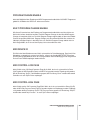
Before you connect the Virus to an AC outlet and the rest of your equipment, ensure that all of the
devices are switched OFF. If your Virus does not have a build-in keyboard, then connect the MIDI
OUT of the desired MIDI send device (keyboard, computer, hardware sequencer, etc.) with the MIDI
IN of the Virus.
Connect the audio outputs of the Virus with the signal inputs of your audio system. In order to
receive a signal, as a minimum you must connect the output OUT 1 R/MONO. However, we recommend you also connect the output OUT 1 L so you are able to enjoy the stereo sounds of the Virus.
Once you have established the desired cable connections, make sure the main volume controls of
all the connected devices (Virus: MASTER VOLUME, located at the upper left hand of the control
panel) are dialed to the lowest possible setting. Switch the devices on in the following sequence:
the MIDI send device (computer, master keyboard, etc.) first, then the sound generators (Virus and
the other signal sources), followed by the mixing console and finally the amplifier.
Now while you are sending notes on MIDI Channel 1 of the Virus, turn the master volumes of the
connected devices up in the same order that you switched the devices on. Be sure to keep on eye
on the signal level indicators of your mixing console.
LISTENING TO THE FACTORY SOUNDS
The program memory of the Virus was loaded with sound programs (SINGLE PROGRAMs) and
sound combinations (MULTI PROGRAMs) before it left the factory. To hear the SINGLE PROGRAMs
(and gain an initial impression of the possibilities your new instrument has to offer in terms of
sounds), first make sure your MIDI source is sending on MIDI Channel 1.
Press the SINGLE button. A number, a letter, number and name appear in the display. These indicate the the MIDI Channel, the current Program Bank (A to D) as well as the number and name of
the current sound program. Now if you play notes you should be able to hear this sound and a ≤
note (the round dot at the end of the note staff is solid black) should appear in the display every time
you press a key and release a key. If you do not hear a sound but you see a half note (blank note
head) check to see if you are sending on the wrong MIDI Channel.
Press the VALUE button to call up the 128 single programs of Bank A in sequence. (The VALUE pot
is inactive in this operating mode.) In order to hear the sound programs in banks B, C and D, simply
use the PARAMETER/BANK buttons to step from one program bank to another.
You’ll find that some sound programs are labeled with the abbreviations ”INP” or ”VOC”. These use
the external audio input as a signal source for the filter section (INP) or vocoder (VOC). This means
that you won’t hear anything until you route an audio signal into the external audio inputs.
16
LISTENING TO THE MULTI PROGRAMS
The Virus not only has the capability of playing SINGLE PROGAMs, but also combinations consisting of more than one sound simultaneously (MIDI Multi Mode). To call up the MULTI PROGRAMs,
press the MULTI button and select these combination programs via the VALUE button. The Virus
features “only” 128 MULTI PROGRAMs, so you don’t have to switch back and forth between banks
they way you just did while activating single programs.
The majority of available MULTI PROGRAMs contain sound combinations that are controlled via a
single MIDI channel. In these MULTI PROGRAMs, the sounds involved are allocated side-by-side
(split) or on top of one another (layered) on the keyboard. In other MULTI PROGRAMs, the sounds
are divided up over several MIDI channels to make it easier to work with a sequencer. If you activate
a MULTI PROGRAM and hear a single sound only, then you can control this MULTI PROGRAM via
several channels.
YOUR FIRST SOUND PROGRAM
If you have never created or changed a sound on a synthesizer, we now have the pleasure of introducing you to this fascinating process.
Select the single program “A127 - START -”. Press any key on the connected keyboard. You should
hear a sound that, for lack of better description, is a bit harsh or biting, but above all completely
static. It should start immediately after you press a key and sustain indefinitely for as long as you
hold the key down. As soon as you release the key, the sound should end abruptly. This sound is
not designed to be especially pleasant; it is intended to be as neutral as possible to give you a basis
from which you can begin creating or shaping your own sound.
VIRUS CLASSIC MANUAL
Introduction
17
The Amplifier Envelope
Long-term exposure to this sound will definitely grate on your nerves, so let’s get started with
changing it into a signal you might enjoy hearing, beginning with the volume characteristics. Locate
the section labeled AMPLIFIER at the bottom right of the control feature panel of the Virus. Here you
can see five pots labeled ATTACK, DECAY, SUSTAIN, TIME and RELEASE, respectively.
These controls will help you to dial in volume characteristics called an amplifier envelope and put an
end to the nerve-racking drone that may remind you of one of those cheesy organs that you hear in
‘60s B-movie sound tracks.
Rotate the ATTACK pot while you repeatedly engage a key to hear the note. The further you turn the
pot up, the longer it takes for the sound to achieve maximum volume after the start of the note. So
you can say ATTACK controls the initial volume swell of the sound.
Presumably the ATTACK pot was set to a random position before you made any adjustments. Nevertheless the volume automatically increased to the maximum level before you started rotating the
pot. The reason for this is that an ATTACK value of 0 is saved in the sound program - START - and
this value remains valid until you determine a new value by adjusting the position of the pot, even if
you turn it ever so slightly.
Take a look at the display of the Virus to gain an impression of the difference between these two
values. It shows two numeric values when you dial a pot: at the left you can see the value stored in
the sound program and at the right, the numeric equivalent to the value determined by the current
position of the pot.
Always keep in mind that for a programmable synthesizer the position of the control feature
or pot does not necessarily indicate the actual value of the given function. The reason for this
is that when you first activate a sound program, it will reflect the programmed value. You
have to adjust the control feature before the programmed value is superseded by the value
you determine manually.
Now fiddle with the DECAY pot while you repeatedly press a key to activate a note. Hold the key
down for good while. You will notice that the volume, once it reaches maximum level at the end of
the ATTACK phase, drops until it reaches a minimum level. The DECAY pot determines the speed,
or in synthesizer jargon, the rate at which the volume decreases.
However, the DECAY level does not always drop to the minimum level; you can determine a random
value between the maximum and minimum levels at which the volume remains constant. This level
in turn is controlled via the SUSTAIN pot.
Whenever the SUSTAIN level is set to maximum, the volume cannot drop during the DECAY phase;
in other words, in this situation the DECAY pot is ineffective.
18
The individual functions of a synthesizer are designed to interact; many functions are dependent on
other functions. In a number of cases this means that some functions are subordinate to others, i.e.
the effectiveness of a control feature is altered, modified or even negated completely by other related functions.
The final pot, RELEASE, determines the speed or rate at which the volume decreases when you
release the key: At low values the sound ends relatively abruptly, at high values, the sound fades out
more gradually and softly. The length of the RELEASE phase also depends on which level the amplifier curve is at when you release the key: The lower the level, the shorter the RELEASE phase. If you
dialed in a brief DECAY or SUSTAIN-TIME phase and it ended while you held the key down then of
course there will not be an audible RELEASE phase.
The next phase of the amplifier envelope is determined by the SUSTAIN-TIME pot: If the pot is set
to the center position (12 o’clock) indicated by the mathematical infinity symbol, then the SUSTAIN
level remains constant through to the end of the note.
If you turn it counter-clockwise to the left (towards FALL), then the level drops off at an increasing
rate towards the minimum level much in the manner you just experienced with the DECAY pot; If
you turn the pot clockwise to the right (towards RISE), the level rises at an increasing rate to maximum and remains there until you release the key.
The amplifier envelope can be described as a variable curve which, depending on the type and
duration of attack, hold and release data, automatically influences an imaginary volume pot (turns it
up or down). At the beginning of the note, ATTACK controls the rise or rate of increase to the maximum level. Once the maximum level is achieved, DECAY determines the fall or rate of decrease to
the SUSTAIN value, which is infinitely variable between the minimum and maximum levels. The
amplifier envelope may remain at this value until the end of the note, fall towards the minimum level
as determined by the variable TIME value, or even rise again towards the maximum level. After the
end of the note, RELEASE controls the fall or rate of decrease to the minimum level. Consequently,
the control pots labeled ATTACK, DECAY, TIME and RELEASE control a speed or rate, where as
SUSTAIN actually controls a level.
VIRUS CLASSIC MANUAL
Introduction
19
The First Filter
Now we will take a look at a component of a synthesizer that is generally regarded as the most
important functional unit as it enables drastic sound shaping measures: the filter - or in the case of
the Virus, the two filters. But first we will concentrate on just one of the two filters.
Locate the CUTOFF pot (not to be confused with CUTOFF 2) in the section labeled FILTERS,
directly above the section labeled AMPLIFIER. Rotate the pot to the left and right and note how the
sound becomes muddier and clearer in response to the direction in which you turn the pot. (To
ensure this effect and the following aural experiments are most pronounced, adjust the amplifier
envelope so that the Virus generates a constant level while you hold a key down).
This is how a low pass filter works: it suppresses, or in technical jargon, attenuates the higher frequencies in a signal and allows the lower frequencies through. Think of the CUTOFF pot as a
bouncer and the Virus as your pub. You can tell it which frequencies to let in and which frequencies
to keep out. The frequencies above the so-called cutoff or filter frequency are suppressed, those
below it remain unaffected.
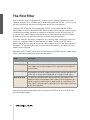
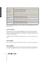
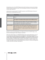
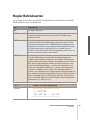
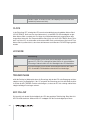
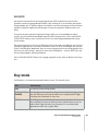
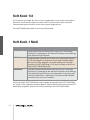
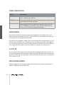
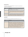
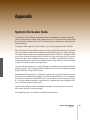
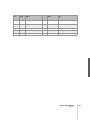
Now locate the FILT 1 MODE switch, which is also located in the FILTERS section. It enables you to
select a filter operating mode from the four available options:
Mode
Description
LOW PASS (LP)
the low pass filter we have just discussed.
HIGH PASS (HP)
the high pass filter which works in the opposite manner of the low pass filter: It suppresses the lower frequencies in a signal and lets the higher frequencies pass.
BAND PASS (BP)
the band pass filter which suppresses both ends of the tonal spectrum and
allows only a narrowly defined bandwidth of the original sound to pass.
BAND STOP (BS)
The band stop filter, band reject filter or notch filter which works in the
opposite manner of the bandpass filter. It allows all of the frequencies of a
signal except for a narrow frequency band around the cutoff to pass. The
term “notch” is fairly descriptive; you might say this filter chops a notch out
of the sound spectrum.
Now activate the different operating modes and rotate the CUTOFF pot to get a feel for the way
each filtering option works.
20
Along with the CUTOFF pot, the RESONANCE pot is the most important control feature of a filter.
The filter resonance increases the volume of the frequencies located near the cutoff frequencies and
suppresses the more remote frequencies. This sound shaping feature has a striking effect - especially when used in conjunction with the low pass filter: it produces a nasal or honking type of tone
which increases as you turn the resonance up. Experiment by varying the RESONANCE setting in
the different operating modes in conjunction with different CUTOFF settings. You will find the effect
that the RESONANCE pot achieves is markedly different for the band stop filter in comparison to
the effect it has on the other filter types: as the resonance increases, the bandwidth of the notch
decreases; in other words more frequencies on both sides of the filter frequency are allowed to
pass.
Filter Modulation
Of course we don’t want to require you to execute every sound modification manually by twiddling
pots. All kinds of sound modifications in the Virus can be executed automatically much in the way of
your previous experiments with the volume controls: The amplifier envelope can be described as a
variable curve which, depending on the type and duration of attack, hold and release data, automatically influences (turns it up or down) an imaginary volume pot.
Similar procedures are applicable to the filter frequencies. The FILTERS section features its own
envelope, the structure of which is identical to the amplifier envelope, located directly above the
amplifier envelope on the control feature panel. Much like the amplifier envelope, the filter envelope
automatically “rotates” the CUTOFF pot.
However there is one significant difference between the two envelopes. With the amplifier envelope,
you are always dealing with an initial volume level of 0 because of course you want absolute silence
prior to the beginning of a note. After the RELEASE phase, it is again highly desirable that your box
is silent. With the filter envelope, the situation is somewhat different: It always starts at the CUTOFF
value that you determined manually. And it is definitely not always desirable that the filter frequency
is brought to the maximum level.
Consequently, you need a tool that limits the effective range of the filter. This is why we equipped
the Virus with a control labeled ENV AMOUNT (short for Envelope Amount). When the pot is turned
counter-clockwise to the far left, the filter has no effect on the cutoff frequency; the further you turn
the pot to the right, the greater the effect the filter envelope has on the filter frequency. The maximum level of the envelope may lie outside the audible range when the filter has already been par-
VIRUS CLASSIC MANUAL
Introduction
21
tially opened via the CUTOFF pot or was manipulated via other control options. In extreme cases
where the filter is already completely open, the filter frequency cannot be increased regardless of
how high you set the ENV AMOUNT.
Go ahead and spend some experimenting with different ENV AMOUNT, CUTOFF and RESONANCE
settings for the diverse filter operating modes. Also try varying the settings for the amplifier envelope. You will find that with just these few parameters you are able to come up with a vast amount of
sound settings. If you are among the many musicians who are associative listeners, you might say
many of the settings produce sounds reminiscent of stringed-instruments; some sound picked,
plucked or snapped, others sound bowed.
For your next experiment set the amplifier envelope so that you hear a constant level when you
press and hold a note. Now deactivate the filter envelope by setting the ENV AMOUNT to 0. Set Filter-1Filter-1 to low pass mode and decrease the filter frequency until you just barely hear a muddy
signal when you play notes in the mid-range.
Now play a few higher and lower notes. You will find that the lower notes have a greater overtone
content, whereas the higher notes sound muddier and their volume decreases until the notes are
completely inaudible. You might already suspect what this is all about: As the notes are transposed
ever lower, more portions of the signal fall below the cutoff frequency, whereas with the notes that
are transposed ever higher, more portions of the signal rise above the cutoff frequency and subsequently are suppressed until the root note and the last audible portion of the signal is silenced.
To avoid this effect - or if desirable, to amplify it - you have the option of influencing the cutoff frequency via the pitch of the note, i.e. the note number. The degree of influence is determined by the
KEY FOLLOW pot.
Please note that KEY FOLLOW is a so-called bipolar parameter: Its control range is not limited to
the positive end of the spectrum (0 to a maximum of 127). Bipolar controls effect negative values as
well, in this case from the negative maximum of -64 through 0 an on to the positive maximum of
+63. Consequently, if this pot is set to the center position (12 o’clock or 0) the pitch of the notes
corresponding to the keys on your keyboard has no effect on the cutoff frequency. If on the other
hand you turn the KEY FOLLOW pot clockwise towards the positive control range, you will find that
the filter opens up increasingly as the pitch increases with higher notes. At lower notes, the filter
closes down again. If you turn the pot counter-clockwise towards the negative control range, the
KEY FOLLOW effect is reversed. With the Virus, you will encounter this feature - intensity control via
a bipolar parameter - again in conjunction with other modulation sources and targets.
Now experiment as much as you like with different KEY FOLLOW settings and tune the settings via
the CUTOFF pot. And remember to bring all of the other parameters you have encountered thus far
into play.
22
The Saturation Stage
In the signal chain of the Virus, Filter-1 is followed by a saturation stage. It enables you to add overtones to the filtered signal via distortion. Locate and press the button labeled EDIT in the FILTERS
section.
MENU
FILTER EDIT > SATURATION > CURVE
DISPLAY
01111111111111111112
1 SATURATION
Curve
Off≤
61111111111111111154
The display will read ”SATURATION CURVE OFF”, which means exactly what it says. With the
VALUE buttons or the VALUE pot, you can now select from a number of saturation/distortion
curves. Next to the distortion curves, the SATURATION stage offers further DSP effects such as the
shaper, rectifier and filter. These are explained in detail in the section on the SATURATION stage.
At this point we would like to mention the OSC VOL pot in the MIXER section. The portion of the
control range from the far left to the center position (12 o’clock) determines the volume of the filter
section’s input signal. The portion of the control range located to the right of the center position (12
o’clock) does not achieve any increase in volume; it simply intensifies the degree of saturation or
distortion. This effect is only achieved when you have activated a saturation curve. The intensity of
the remaining available DSP effects is also controlled via the OSC VOL knob.
Feel free to experiment with the diverse saturation curves and be sure to vary the OSC VOL settings. Note how the different CUTOFF and RESONANCE settings influence the saturation curve.
VIRUS CLASSIC MANUAL
Introduction
23
The Second Filter
You probably noticed that by a adding a bit of saturation to the signal you can come up with a pretty
heavy, aggressive sound - especially with a low filter frequency level and high resonance. You’re
probably thinking these types of sounds could do with some more filtering. We had the same idea,
which is one of the reasons why we equipped the Virus with another filter per voice.
The technical design of this second filter is identical to the first, so we won’t discuss it in as much
detail as we did the first filter. However, there are few differences in how you handle the second filter:
Only two control features of the Virus are allocated exclusively to Filter-2: CUTOFF 2 and FILT 2
MODE.
The RESONANCE, ENV AMOUNT and KEY FOLLOW pots can be allocated to either of the two filters or both simultaneously. Use the two SELECT buttons located at the far right of the FILTERS
section to select the desired operating mode. For instance, if you press the FILT 2 SELECT button,
then the values you set via the RESONANCE, ENV AMOUNT and KEY FOLLOW pots apply exclusively to Filter-2. The corresponding parameters of Filter-1 remain unaffected. On the other hand, if
you press both SELECT buttons at the same time, the values that you dial in apply by the same measure to Filters 1 and 2.
In the sound program we are using for our experiments, the LEDs of both buttons are illuminated, so
that all adjustments to the given parameters affect both filters. However, you have yet to actually
hear the effect of Filter-2 on the signal because it is mixed out of the audible signal path of the Virus.
Before we get started with our next experiment, deactivate SATURATION, set the ENV AMOUNT of
the filter envelope to zero and set CUTOFF 2 to the center position (12 o’clock) so that Filter-2
always has the same cutoff frequency as Filter-1 (we’ll explain CUTOFF 2 a bit later). Set CUTOFF
to a medium or middle value and turn the RESONANCE pot counter-clockwise to the far left to
achieve a relatively muddy sound. Now locate the FILTER BALANCE pot at the upper right hand of
the control panel and rotate it from the left to the right. You will note the sound becomes muddier as
you turn the pot towards the center position (12 o’clock) and that the sound is somewhat brighter at
the far right of the control range then at the far left.
The reason for this effect is that when you turn the FILTER BALANCE pot to the far left, only Filter-1
is audible. When you rotate the pot to the right, Filter-2 is blended in so that it follows Filter-1 in the
signal chain. When you turn the FILTER BALANCE pot clockwise, Filter-1 is blended out of the signal chain until at the far right position only Filter-2 is active and audible.
Each filter in the Virus normally features 2 poles. However in the FILTER ROUTING operating mode
SER 6, Filter-1 operates with 4 poles, so the signal patched through Filter-1 (FILTER BALANCE to
the far left) is trimmed more drastically than when it is routed through Filter-2 (FILTER BALANCE to
24
the far right). When you set the FILTER BALANCE pot to the center position (12 o’clock) - as we
mentioned before - the two filters are routed in series, which means they respond as if they were a
single filter with 6 poles and consequently a great deal of slope. This is why the input signal is
trimmed substantially when you set the pot to this position.
Experiment with the diverse FILTER BALANCE positions to get a feel for the different degrees of
slope. Rotate the CUTOFF pot or activate the filter envelope (for both filters!) to hear the filters in
action.
The CUTOFF 2 pot is a special feature: It controls the cutoff frequency of the second filter, but is
subordinate to the CUTOFF pot located above it. In other words, at the center position (12 o’clock)
the manually selected frequency of Filter-2 is identical to that of Filter-1. When you rotate the pot to
the left the cutoff frequency level of Filter-2 is increased relatively to Filter-1, when you turn to pot to
the right the cutoff frequency level is decreased relatively. Now when you adjust the CUTOFF pot,
you adjust the cutoff frequency of both filters by the same measure! This feature lets you determine
a difference in values in the filter frequencies (called an offset) via the CUTOFF2 pot which remains
constant whenever you adjust the CUTOFF pot.
Yet another experiment in which you can come up new filtering characteristics that are typical of the
Virus:
Set the FILTER BALANCE pot to the center position (12 o’clock) and CUTOFF 2 to the maximum
level. The FILTER ROUTING operating mode must remain SER 6. Set CUTOFF and RESONANCE to
a middle value and select a clearly audible SATURATION curve.
Now you can filter this complex signal produced by a combination of the saturation stage and the
Filter-1 yet again. Rotate the CUTOFF 2 pot slowly towards the center position (12 o’clock). You can
hear how Filter-2 gradually modifies the distorted signal. You can set a RESONANCE value for Filter-2 if you press the FILT 2 SELECT button and rotate the RESONANCE pot to the desired position.
Set the CUTOFF 2 pot to a position to the right of the center position. This configuration can be
described as a complex non-linear filter set up where the cutoff frequency is controlled via the CUTOFF pot. You can dial in a wide range of sound-shaping option via CUTOFF 2. Also try modifying
the resonances of both filters as well as the SATURATION curve to come up with different filtering
characteristics.
Now experiment with the diverse filter modes and listen closely to the effect of the parameters RESONANCE, ENV AMOUNT and KEY FOLLOW in conjunction with the SELECT button. Please also
keep in mind that the chances of choking a sound off are substantially greater when you are using
both filters: For instance, if the first filter is used as a low pass with a low cutoff frequency and the
second as a high pass with a high cutoff frequency, the Virus will not generate an audible signal
when you set the FILTER BALANCE pot to the center position (12 o’clock).
VIRUS CLASSIC MANUAL
Introduction
25
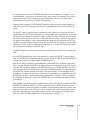
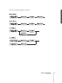
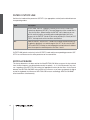
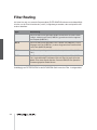
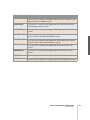
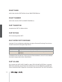
Filter Routing
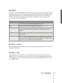
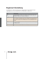
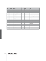
The final parameter we’ll discuss for the time being is FILTER ROUTING. This feature offers several
filter routing options which allow you to operate the filters in series, i.e. patch one after the other in
the signal chain, or in parallel, which means side by side in the signal chain
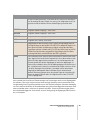
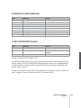
Regardless of which FILTER ROUTING option you chose, the SATURATION stage is always post-Filter-1, i.e. after Filter in the signal chain.:
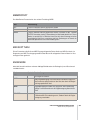
Mode
26
Description
SER-4
The filters are switched in series; with two poles each (12dB/Okt.), both filters have the same slope for a total of four filter poles (24dB/Okt.).
SER-6
The filters are switched in series; Filter-1 has four poles (24dB/Okt.), Filter-2
has two poles (12dB/Okt.) so the overall slope is equivalent to six poles
(36dB/Okt.).
PAR-4
The filters are switched in parallel and feature two poles each (12dB/Okt.).
SPLIT
The filters are switched in parallel and feature two poles each (12dB/Okt.).
Additionally, they receive independent input signals (more on this later).
Each of the two oscillators routes its signal into one of the two filters whose
signals can be spread in the panorama via a parameter called UNISON Pan
Spread.
Her is the filter routings capabilities of the Virus.
VIRUS CLASSIC MANUAL
Introduction
27
The First Oscillator
To this point, we have turned our attention exclusively to sound-shaping functions and have always
started with the same basic material: a so-called sawtooth wave. This waveshape is especially wellsuited as a neutral starting point as it contains all of the so-called natural scale of overtones, which
give the filter plenty of quality material to work with.
The filters, with the exception of a notch filter or band stop (BS), trim the far reaches of the tonal
spectrum, so for instance a signal sounds muddier after it has been routed through a low pass filter.
You can well imagine that this type of sound modification is substantial but insufficient for shaping
more subtle differences in tone. For instance the tone of a trumpet differs significantly from that of a
saxophone even though no one would seriously claim that either of the instruments has a muddier
tone than the other.
What you need is a sound-shaping option for the portion of a signal that a filter allows to pass. And
of course you also need a tool for determining the pitch of a signal. In synthesizers, both of these
tasks are executed by oscillators. They oscillate at a variable pitch that can be modulated and they
also generate different waveshapes which give the filters a wider variety of material to work with.
The Virus is equipped with two main oscillators and a so-called suboscillator. We will first take a
look at Oscillator 1, which is the oscillator you have already heard in action during your experiments
thus far.
Dial in the same basic sound that you started with at the very beginning. Now modify the amplifier
envelope so you are working with a less grating sound, but hold back on any other filter or saturation modifications so you can hear the purest oscillator signal possible.
Locate the section labeled “1”, it is bordered off in a separate area at the far left of the section
labeled OSCILLATORS. No check out the two pots labeled SHAPE and WAVE SEL/PW. These enable you determine the waveshape and consequently the tonal spectrum of Oscillator 1.
In the sound program, SHAPE is preset to the center position (12 o’clock), which is equivalent to a
value of 64. On the pot, this position is identified via a graphic depiction of a sawtooth wave. You
can definitely see why this waveshape bears the name “sawtooth.” Press and hold a key and slowly
turn the pot clockwise. You should be able to hear how the tone becomes increasingly more hollowsounding. You might say this effect thins the sound out, but in any case, the entire tonal spectrum is
affected by an equal measure, which is an audio result filters are unable to achieve.
The waveshape that is audible when you turn the SHAPE pot to the far right is a so-called pulse
wave. The graphical representation of this waveshape on the control panel gives you a good idea of
its appearance. It is unique because the duration of the negative pulse is equal to the duration of the
positive pulse: It has a so-called pulse width of 50%. The tone of a pulse wave is different to that of
a sawtooth wave because it does not contain all overtones in the natural overtone scale, only the
28
odd-numbered tones, i.e. the first (the root note that determines the pitch), third, fifth, and so forth.
By turning the SHAPE pot from the sawtooth control range towards the pulse control range, you are
actually dialing every other overtone out of the mix, which explains why the sound becomes thinner.
You can continue modifying the sound by reducing the symmetrical width of the pulse wave. In the
Virus, you can execute this sound-shaping measure via the WAVE SEL/PW (PW = pulse width) pot,
PROVIDED THE SHAPE POT IS SET TO A POSITION IN THE RIGHT HALF OF ITS CONTROL
RANGE (LATER THAN 12 O’CLOCK). Rotate the WAVE SEL/PW pot slowly from the left to the right
and leave the SHAPE pot at the far right position. You can hear how the treble content of the sound
increases while the sound becomes ever thinner. At the far right position, the signal is no longer
audible because the pulse width is equivalent to 0% and consequently the wave no longer oscillates.
Starting at the center position (12 o’clock) indicated by the sawtooth, turn the SHAPE pot counterclockwise towards the left. You can hear how the overtones are increasingly mixed out of the signal
until you can only hear the root note. This sound is produced by a so-called sine wave, one of 64
other waveshapes that you have at your disposal for sound generation purposes. These waveshapes can also be activated via WAVE SEL/PW (WAVE SEL: Wave Select), PROVIDED THE SHAPE
POT IS SET TO A POSITION IN THE LEFT HALF OF ITS CONTROL RANGE (EARLIER THAN 12
O’CLOCK). Regardless of the current SHAPE setting, you can also select a wave in the EDIT menu
under Oscillator 1 WAVE.
Go ahead and check out the different waveshapes. The second of the 64 waves is a triangle wave,
the remainder of the waveshapes are each a unique tonal blend. After you have familiarized yourself
with this raw material, experiment with the parameters of the FILTERS and AMPLIFIER sections you
have dealt with thus far (don’t forget about SATURATION and the corresponding function of the
OSC VOL pot), to get a feel for how the diverse waveshapes respond to filtering, saturation and
amplifier modifications.
The Second Oscillator
As we mentioned previously, in addition to the other sound sources, the Virus is equipped with a
second oscillator. Judging from the amount of control features on this oscillator’s section of the
control panel, you have probably already gathered that it has more sound-shaping options than
Oscillator 1.
VIRUS CLASSIC MANUAL
Introduction
29
Dial in the basic sound program that you had at the very beginning; change the amplifier envelope
to suit your taste. In the sound program, the OSC BAL (Oscillator Balance) pot in the MIXER section
is preset to the far left. In order to hear Oscillator 2 in action, rotate the OSC BAL (Oscillator Balance) pot in the MIXER section to the right. Towards the center position (12 o’clock) you will hear
how the tone is modified and as you rotate the pot further to the right, how the intensity of this modification is reduced. This effect is known as the comb filtering effect. It occurs when two signals with
the same frequency but different phase lengths are mixed. Press the same key on your keyboard
several times with the OSC BAL set to the center position (12 o’clock). You should notice that each
note has a slightly different tone. The oscillators are the source of this effect. The oscillators of the
Virus oscillate freely, consequently every time you play a note, the phase constellation between the
two oscillators is different. For now, leave the OSC BAL POT at the center position (12 o’clock).
You are already familiar with Oscillator 1’s SHAPE and WAVE SEL/PW pots. These functions are
identical for Oscillator 2, so we won’t go into detail on them again.
Locate the pot labeled DETUNE and slowly rotate it to the right from the far left position (which is
preset in the sound program). You can hear the tone start to waver and as you turn the pot further to
the right, how this vibrato effect increases until Oscillator 2 sounds distinctly out of tune with
Oscillator 1. This wavering or vibrato-type effect has a popular traditional in synthesizers. It is used
to achieve chorus effects, create sounds reminiscent of stringed instruments/ string sections or
simply beef up the sound.
The SEMITONE pot enables you to transpose Oscillator 2 by plus/minus four octaves in semitone
steps while Oscillator 1 maintains the pitch. This feature is especially interesting when used in conjunction with two other oscillator functions: synchronization and frequency modulation.
Locate and activate the SYNC button in the Oscillator 2 section (the LED must illuminate). The synchronization function forces Oscillator 2 to restart its wave cycle at the same time as Oscillator 1
waveshape starts its cycle. The initial effect of this measure is that the wavering tone that resulted
from detuning and mixing the oscillator signals disappears.
The SYNC effect really becomes interesting when you transpose Oscillator 2 upwards in comparison to Oscillator 1 via the SEMITONE pot. What happens is that the wave cycle of Oscillator 2 is
interrupted as soon as Oscillator 1 starts its cycle. The pitch of the second oscillator no longer has
the expected effect, instead it generates special tones, in some cases for lack of a better description “screaming” type effects.
The other effect that benefits from manipulating the interval between the oscillators is frequency
modulation (FM). It generates new tonal spectra in which the signal of the first oscillator controls the
frequency of the second oscillator similar to the manner in which filters can be controlled via envelopes. And here too you have a pot which allows you to control the intensity of: FM AMOUNT. Basically, this effect is similar to a vibrato, although here you’re dealing with an extremely fast vibrato
featuring a frequency within the range of human hearing. This signal is not actually audible as a
30
vibrato effect. Instead, you’ll hear a sound modulation, in some cases, a very drastic one at that.
Choose the pure sine waveshape for Oscillator 2. In conjunction with the sine wave, the frequency
modulation generates very clear, in some cases bell-like, spectra.
In the Virus you have the option of combining the two functions called oscillator synchronization
(SYNC) and frequency modulation (FM AMOUNT, to generate new harmonic spectra. Switch SYNC
on and experiment with the FM AMOUNT. Also try out different SEMITONE settings and the diverse
waveshapes of Oscillator.
The Virus is equipped with a third master oscillator that lets you create further oscillations and spectra. You can access the parameters of this oscillator, which are described in a later chapter, via the
OSCILLATOR EDIT menu.
The Mixer Section
You have already come across two parameters of the MIXER section: OSC BAL determines the mix
ratio between Oscillators 1 and 2; in the left half of its control range, OSC VOL determines the master volume of the oscillator mix. In the right half of the control range from the center position to the
far right, OSC VOL increases the saturation intensity when a SATURATION curve has been activated.
Now we’ll take a closer look at the final control element, the SUB OSC pot: It controls the volume of
the fourth oscillator, the so-called SubOscillator, which always operates an octave below
Oscillator 1.
The SubOscillator is mixed to the Oscillator 1 and 2 master mix signal as determined by the OSC
BAL pot. The master volume of the composite mix is controlled by the OSC VOL pot. The only other
parameter available for the SubOscillator is accessible via the OSCILLATOR EDIT menu where you
have the option of selecting a triangle or pulse waveshape (SUB OSCILLATOR WAVE SQUARE/TRIANGLE).
Another voice-internal signal source of the Virus has no visible control features on the control panel:
the Noise Generator. The dedicated sound parameters are its volume and coloration (NOISE Volume
and Color in the OSCILLATOR EDIT menu). On the middle position of NOISE Color the Noise Generator produces white noise. Please keep in mind that the level of the Noise Generator is not subject
to the master volume controlled by the OSC VOL pot. In other words, it is audible even when OSC
VOL is set to zero.
VIRUS CLASSIC MANUAL
Introduction
31
The VIRUS’ ring modulator is a new sound source. The output of the two oscillators is multiplied to
create interesting sounds with rich enharmonic overtones. These overtones are highly dependent
on the frequency coherence of both oscillators and it’s waveforms. The frequency coherence can be
changed, for instance use the OSC2 SEMITONE parameter. To blend in the ring modulator use
EDIT: RINGMODULATOR VOLUME (in OSCILLATOR EDIT Menu). If the RINGMODULATOR VOLUME is zero, the ring modulator is switched off. OSC VOL does not affect the ring modulator level
(or indeed the noise volume). Therefore the original oscillator signal can be leveled independently of
the ring modulator. Be sure to check out what the ring modulator does when you select a sine wave
for Oscillator 1 and 2.
Now we can go on and solve the mysteries of the signal flow as determined by the FILTER ROUTING operating mode SPLIT: Here Oscillator 1 and the SubOscillator are routed to Filter-1, whereas
Oscillator 2 and the Noise Generator are routed to Filter-2. Although the sound sources are split into
two signal paths, you can still control the volume levels of the different elements as well as OSC
VOL in the usual manner.
The LFOs
When you first started this series of experiments with sounds, we promised that many of the functions the Virus can be “programmed” so that they are executed automatically. You have already
learned how to control the volume and cutoff frequencies of both filters as well as the pitch and
intensity of the frequency modulation of Oscillator 2 via “preprogrammed” envelopes. These
options are great, but you have already encountered a number of functions where it would be a
helpful if you could also program them to be executed automatically. And of course envelopes are
great modulation sources, but you have to play a note every time you want to initiate an envelope.
During your experiments you probably came across a function or two you would like to be able to
control periodically - independently of notes. Some features that come to mind are traditional techniques such as vibrato (periodic pitch control) and tremolo (periodic volume control). Another option
you might like to have at your disposal is random parameter control.
In the Virus, both of these tasks are executed by a so-called LFO (low frequency oscillator) that
oscillates at frequencies below the audible range. An LFO is similar to the oscillators you have
encountered thus far, but it oscillates significantly slower so that its output signal is too low for
human hearing. So what good are they if you can’t hear them? LFOs are used in much the same
manner as envelopes, with the major difference that the are repeated indefinitely.
32
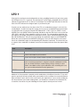
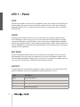
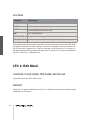
LFO 1
Start with the usual basic sound configuration or chose a modified sound to suit your taste. Locate
the RATE pot in the LFO 1 section of the control panel. The RATE pot is equipped with an LED that
indicates the speed of the LFO as well as its waveshape. Turn the RATE pot and check out how the
flash of the LED indicates the change of pace as you rotate the pot.
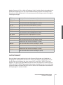
Currently you are unable to hear the effect of the LFO as its modulation intensity is set to 0 in the
sound program. In order to change this setting, you must access the AMOUNT button which works
in conjunction with five vertically arrayed LEDs labeled OSC 1, OSC 2, PW 1+2, RESO 1+2 and
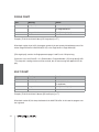
ASSIGN: Press the AMOUNT button repeatedly and observe how the LEDs flash in succession (the
LEDs OSC 1 and OSC 2 flash separately as well as in unison). The corresponding modulation targets appear in the display, along with the modulation intensity values as determined by the VALUE
pot and VALUE buttons. (You can also scroll through the modulation targets via the PARAMETER
button after you have pressed the AMOUNT button once.) Once you have dialed in a value other
than 0 for a modulation target, the corresponding LED illuminates continually. This feature tells you
at a glance that a modulation is underway even when the display indicates some other type of operation.
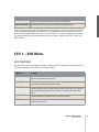
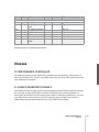
Value
Description
OSC-1
refers to the frequency of Oscillator 1
OSC-2
refers to the frequency of Oscillator 2
PW 1+2
means that the pulse widths of both oscillators are controlled in unison
RESO 1+2
refers to the resonances of both filters. Please keep in mind that although
each set of these parameters is assigned a common modulation intensity,
you can still dial in different sound-shaping settings manually. In other
words, the audible result of a joint modulation varies according to the values you have determined for the other parameters.
ASSIGN
Here you can freely select any modulation destination.
Modulate the five parameters separately and in combinations with different intensities. Try to anticipate the sound you will come up with when you modulate the first oscillator, the second oscillator or
both oscillators at once and see if the results match your expectations. If you can fairly reliably predict the outcome of your sound-shaping efforts, you should have a handle on the information discussed thus far and can use your knowledge to create specific sounds you have in mind.
VIRUS CLASSIC MANUAL
Introduction
33
During the course of your experiments, it is entirely possible that you have generated modulations
that have no effect whatsoever on the sound, for instance if you modulate the frequency of
Oscillator 2 although it is dialed out of the oscillator mix. When you run into this type of problem,
check out the signal routing, if any configurations conflict with each other and memorize the situation, problem and solution. If you make a habit out of this, you won’t panic when you run into similar
situations; instead you’ll keep your cool, analyze the unexpected sound and fix the mix.
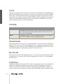
You are currently using a triangle as the LFO waveshape. You shouldn’t have any problem associating the periodic up and down fluctuation of the target parameter with this waveshape. Now activate
the other available waveshapes for LFO 1 and try to picture the respective waveshape and associate it with the results of the modulation.
The third waveshape is a descending sawtooth wave. You can convert it into to an ascending sawtooth by simply dialing in the requisite negative modulation intensities (AMOUNT).
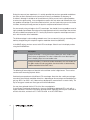
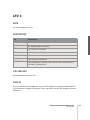
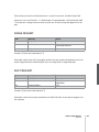
In the WAVE setting, you have access to 64 LFO waveshapes. Select these in the display section
using the VALUE buttons:
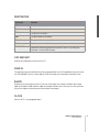
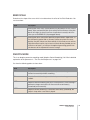
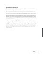
Value
Description
S&H
(Sample and Hold) is a structured random modulation. Here random modulation values are generated. The value is held until the next beat impulse,
then it abruptly jumps to a new random value.
S&G
(Sample and Glide) is a continual random modulation. Here the random values glide seamlessly into one another, the rate of which is determined by
random modulation of the RATE value.
The following 62 waveshapes are identical to the oscillator section’s digital waves. These can be
used to create interesting rhythmic effects.
Continued your experiments with different LFO waveshapes. Note that after a while you no longer
consciously hear minimal modulation intensities - depending on the waveshape and modulation target (e.g. S&G +1 on OSC 1 or 2). However they do pep up the sound of lend it a certain vitality. The
key to many great sounds are these types of minimal modulations.
You may have gathered that the LFOs of the Virus are polyphonic:
If several notes are played simultaneously, these are controlled by dedicated LFOs, each with a
slightly varied rate. This effect livens up the sound of chords, especially when they are sustained. To
enhance this effect, activate the LFO 1 KEY FOLLOW in the LFO-EDIT-Menu.
34
This function enables you to control the rate of the LFOs via the pitch, or more accurately, via the
MIDI note number, so that higher notes generate faster LFO rates. As result, when you press and
hold several notes you will hear all kinds of substantially different periodic fluctuations.
Finally, the LFOs can also be used as additional envelopes. The control feature for this effect is the
ENV MODE button. When you press this button, two things occur: For one, the LFO no longer initiates its cycles periodically, but only once at and in sync with the start of a note, and for the other,
the active range of the LFO is switched from bipolar (in both directions from the zero position) to
unipolar (from zero in one direction only). Please note that this applies to the modulation target but
not the modulation intensity. Here you can still determine a value in the entire bipolar range.
This effect is especially prominent when used in conjunction with the sawtooth wave, which enables
a fade-out type of effect (when you dial in a positive AMOUNT value) or a volume-swell type of
effect (negative AMOUNT) for the available modulation targets. Using the LFO Curve parameter
located in the LFO EDIT menu, you can have the ”ramp” rise or fall exponentially. If you choose a triangle for your waveshape, the device will generate an ascending phase (attack) and a descending
phase (decay). LFO Curve also lets you determine the temporal relationship between attack and
decay; in other words, their respective rates.. Dial in the desired speed via the RATE pot.
You can also use S&H and S&G in ENV MODE to come up with some attractive results: S&H generates a single random value at the start of a note (in this case, the RATE pot has no effect); S&G
works in the same manner although in this case the RATE value is crucial. It determines the amount
of time it takes to glide from the previous to the new random value.
LFO 2
The design of the second LFO is essentially the same as the first, so we’ll spare you the repetition of
details SHAPE 1 and 2 are available as a joint modulation target; the filter frequencies and the Panorama position can be manipulated individually. You may also freely select a parameter for your
modulation destination.
VIRUS CLASSIC MANUAL
Introduction
35
Volume and Panorama Position
You probably noticed that the many of the sound shaping options available in the Virus occasionally
influence the volume level. For instance, an unfiltered sawtooth is naturally louder than a highly filtered sawtooth because whenever you blend a part of the frequency spectrum out of the mix, you
are automatically reducing the overall volume of the signal. This is why the Virus is equipped with a
programmable volume pot for each SINGLE PROGRAM. It enables you to balance out the volume
levels of your sound programs.
Locate the parameter PATCH VOLUME in the COMMON section of the EDIT menu.
MENU
EDIT > COMMON > PATCH VOLUME
DISPLAY
01111111111111111112
1 COMMON
PatchVolume 100≤
61111111111111111154
Its value is set to 100 so that you have a reserve or headroom of 27 volume increments when you
are dealing with highly filtered sounds.
You have already dealt with the Panorama position as a modulation target of LFO 2. Here you can
not only modulate it, but also determine settings manually. For this purpose, use the parameter
PANORAMA which is also located in the OUTPUT section of the EDIT menu. Like many other
parameters, Panorama is a starting point for modulations. For instance you can modulate the Panorama position via LFO 2 even if you have already set the Panorama to the far left position. In this
case of course you will only hear the Panorama position shift to the right.
36
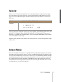
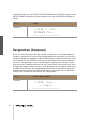
Velocity
Velocity is one of the preferred modulation sources of keyboard players: A light key attack generates a low velocity value for the given note, a heavy touch generates a high velocity value. In the
Virus you have ten modulation targets available for Velocity. Locate the VELOCITY section in the
EDIT menu.
MENU
EDIT > VELOCITY > OSC1SHAPE
DISPLAY
01111111111111111112
1 VELOCITY
Osc1Shape
+0≤
61111111111111111154
There you will find the modulation intensities for: OSC1 SHAPE, OSC2 SHAPE, PULSE WIDTH, FM
AMOUNT, FILT 1 ENV AMT (Filter 1 ENVELOPE AMOUNT), FILT 2 ENV AMOUNT, Resonance 1,
Resonance 2, VOLUME and PANORAMA which you can manipulate independently of one another
in the familiar bipolar control range.
A light key attack generates a low velocity value for the given note, a heavy touch generates a high
velocity value.
Unison Mode
When we talked about the oscillators, we mentioned that by subtly detuning signals, you can beef
up sounds and achieve string-like sounds. The Virus is equipped with features that allow you to take
this type of tonal manipulation a step further. On of these is the so-called UNISON MODE. It enables
you to initiate two or more voices for each note played, which in turn lets you detune many oscillators. UNISON MODE also offers the option of spreading the voices generated by one note in the
stereo panorama and shifting the phases of their LFOs so that all types of periodic effects can be
used to produce an even more exciting signal.
VIRUS CLASSIC MANUAL
Introduction
37
Locate the parameter group UNISON in the EDIT menu.
MENU
EDIT > UNISON > MODE
DISPLAY
01111111111111111112
1 UNISON
Mode
Twin≤
61111111111111111154
UNISON mode determines how many voices the Virus will use to render a played note. In a nutshell,
it determines how ”fat” the sound will be. You can use the UNISON Detune parameter to determine
to which extent the active voices are detuned. UNISON PanSpread distributes them uniformly
across the stereo panorama, a process by which you can also determine the width of a sound’s
stereo base. When you activate UNISON mode for a sound, it can still be played polyphonically.
However, depending on the number of voices you’ve dialed in, its polyphony will of course be considerably reduced in UNISON mode. The most efficient and the standard setting is UNISON mode =
Twin, where two voices are played for every note. In the ”OFF” position, one voice per note is
played.
The Chorus/Flanger Effect
Another function that delivers great effects based on pitch fluctuation is the so-called chorus effect.
Chorus actually consists of a brief delay (generally up to approx. 50 ms) which is varied periodically.
By modulating the delay, the delayed signal is slightly detuned to the input signal (the so-called
Doppler effect). This inconsistency in pitch between the original and effects signal is the source of
the chorus effect. Feedback in the delay line enhances this effect. The left signal side is automatically modulated in a different manner than the right, so a chorus effect is great for converting mono
signals into stereo signals.
If the delay is less than approx. 10 milliseconds, than the effect is called flanging or a flanger effect
rather than chorus. In this case feedback is even more significant because it generates resonances
that can be modulated and is thus yet another source of radical sound effects. If you determine high
feedback values, you can clearly hear how the two sides of the signal are modulated differently - in
reverse phase - by the LFO.
38
Locate the parameter group CHORUS in the EFFECTS menu.
MENU
EFFECTS > CHORUS > DIR/EFFECT LEVEL
DISPLAY
01111111111111111112
1 CHORUS
Dir/Eff
OFF≤
61111111111111111154
CHORUS DIR/EFF determines the balance between the original signal and the processed signal.
The parameters RATE and SHAPE control another LFO that was installed specifically for the chorus
LFO. DELAY is used to set the delay time, DEPTH determines the modulation intensity, and FEEDBACK controls the feedback level. When you want to generate a flanger effect, the FEEDBACK
parameter’s negative control range lets you dial in softer characteristics for the flanger. Please keep
in mind that the Chorus section in the Virus is fully stereophonic: Stereo positions as well as panorama modulations and stereo spread values that you have dialed in elsewhere remain intact in the
effects signal.
The Delay Effect
A delay effect is traditionally used to generated an echo of the input signal. Locate the parameter
group DELAY in the EFFECTS menu.
MENU
EFFECTS > DELAY > EFFECT SEND
DISPLAY
01111111111111111112
1 DELAY
EffectSend
0≤
61111111111111111154
Here you fill find parameters that are virtually identical to the parameters of the CHORUS group. Do
not allow yourself to be confused by the slightly different terminology: The delay time is set via the
parameter entitled TIME (equivalent to DELAY in the CHORUS section); the other features are
FEEDBACK with a dedicated LFO and the familiar parameters RATE, DEPTH and SHAPE.
VIRUS CLASSIC MANUAL
Introduction
39
Only two functions in the Delay section are different to the Chorus section: For one, it features an
EFFECT SEND instead of the balance parameter DIR/EFF. EFFECT SEND is especially significant in
MULTI MODE, where several PARTs with different levels are patched through the same delay effect.
For the other, LENGTH enables you to create substantially longer delay times, for instance to
achieve complete echoes (maximum of 693 ms) that are fully audible. The LFO allows you to modulate the delay as you would the chorus to achieve similar detuning effects. A stereo effect is
achieved via different modulations of the left and right sides of the signal.
More to Come
We have come to the end of these detailed instructions for novices. We hope we were able to help
you become a bit more familiar with your new synthesizer and gain some confidence in how to handle it. As we mentioned earlier, this is just an introduction and does not cover all the functions and
features of the Virus, only the basic components and how they affect the sound of the Virus. You
should now be able to come to terms with the in-depth look at the Virus in the following section.
40
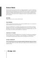
Concept And Operation
Operating Modes
In the Virus you can select from two basic operating modes, SINGLE MODE and MULTI MODE.
In SINGLE MODE, the Virus is able to generate a single sound program only. All 24 voices, all
effects and most importantly, all control features (with the exception of the MULTI button) function in conjunction with this one sound program. You might say a SINGLE program is a combination of all functions and effects that determine the sound of the Virus. In other words: A
SINGLE program is a ”sound” of the Virus, that can be stored and recalled.
The Virus provides access to 1024 SINGLE sounds. Next to the 768 RAM sounds (Bank A and
Bank B), you have six banks available with a total of 1024 factory sounds. These banks, C to H,
are stored in the FLASH ROM and can not be overwritten via STORE.
The MIDI receive channel in SINGLE MODE is the Global Channel. You can change the Global
Channel in the CONFIG menu.
In MULTI MODE, the Virus can combine up to sixteen (SINGLE) sound programs, among which
the maximum available number of 24 voices are allocated dynamically. All simultaneously available sounds can be manipulated in real-time; for this purpose the control panel enables you to
switch among the sixteen so-called PARTS.
In MULTI MODE, the actual sound parameters are augmented with other functions that deal
with how the involved SINGLE programs are structured or organized. These include the volume
levels of the single programs, their MIDI channels, output assignments, etc.
On the Virus, we differentiated fundamentally between SINGLE mode and MULTI mode. This
distinction is reflected in the contents of the menus: If the LED on the SINGLE button lights up,
the CONFIG and EDIT menus let you access the sound parameters of the current SINGLE program. If the LED on the MULTI button lights up, the CONFIG and EDIT menus will contain the
appropriate ”administrative” parameters for the current MULTI program. For example, here you
have the option of selecting the SINGLE program for each of the 16 MULTI PARTs.
VIRUS CLASSIC MANUAL
Concept And Operation
41
The Multi-Single Mode
In MULTI mode, the EDIT and CONFIG menus are responsible for administering the 16 PARTs. Consequently, you can’t access SINGLE program parameters directly here. Beyond that, you’re unable
to change the SINGLE programs directly here, which would admittedly be a handy option when
you’re working with a sequencer. This is why the Virus features MULTI SINGLE mode, which, strictly
speaking, is more an alternative view of MULTI mode rather than a further mode in its own right.
Activate MULTI SINGLE mode by pressing the MULTI and SINGLE buttons simultaneously. The
name of the selected MULTI program will disappear and instead you’ll see the name of the SINGLE
program for the selected PART. Now you can page or scroll through the 16 PARTs using the PART
buttons and select a SINGLE program for every channel. You can process the currently selected
PART or, more accurately, edit its sound, using the control features. The CONFIG and EDIT menus
let you access the usual SINGLE parameters. In this operating mode, you’ll find that the CONFIG
menu has been expanded to include some organizational parameters, for instance, the PART’s volume level, panorama and output assignments. You’ll always see the number of the selected PART
on the upper left in the display. The PART buttons don’t actually change sounds, they simply set the
user interface of the Virus to the desired PART. Irrespective of the given setting, all PARTs can be
controlled simultaneously via MIDI. Consequently, MULTI SINGLE mode, which makes handling so
much easier, is the ideal choice when you’re working with a connected sequencer.
Please bear in mind that MULTI SINGLE mode is really just another view of the normal MULTI mode.
MULTI SINGLE mode doesn’t offer a unique data type for storing sounds, it always works with the
MULTI program currently selected in normal MULTI mode. All of the normal MULTI mode parameters (keyboard zones, etc.) remain intact and in force even though you can’t view or vary them in
MULTI SINGLE mode. You can set the device to normal MULTI mode at any time by pressing the
MULTI button. To return to the MULTI SINGLE mode view, simply press the MULTI and SINGLE buttons simultaneously.
When you’re working with a sequencer, start with a MULTI program that features neutral settings for
its ”administrative” parameters, for example, the MULTI program M0 Sequencer. Here the PART
numbers are identical to the MIDI channels of the PARTs. Now when you work in MULTI SINGLE
mode, the Virus responds as if it were in SINGLE mode, except that you have 16 sounds available
simultaneously on 16 MIDI channels. Use the PART buttons to select these sounds.
You only need to exit MULTI SINGLE mode when you want to store the MULTI program, for example, to save the current global delay/reverb setting. In MULTI mode, these settings are not stored
along with SINGLE sounds.
In addition, you can activate another complete MULTI program in MULTI mode only.
42
Edit Buffers
Whenever you play or edit a SINGLE program, its current data is stored in an edit buffer. This is an
individual memory slot for SINGLE programs that has nothing to do with the memory slots in the
sound banks. When you activate a new SINGLE, its data is copied to the edit buffer. There you can
edit it as you see fit while the original remains unchanged in the bank. When you activate STORE
(more on this in a bit), the content of the edit buffer is copied back to the original slot in the bank (or,
if you so desire, to another memory slot).
In MULTI mode, you have one MULTI edit buffer and 16 SINGLE edit buffers for the PARTs at your
disposal. When you activate another a MULTI program, its data is copied from the MULTI bank to
the MULTI edit buffer. The MULTI program in turn contains address information for the SINGLEs
involved, in other words, the bank and program numbers. These addresses are also copied from the
SINGLE banks into the 16 SINGLE edit buffers for the PARTs.
When you store a MULTI program, only the addresses of the SINGLE programs’ original slots are
saved, but not, however, the sound data in the 16 SINGLE edit buffers. These must be stored separately in the SINGLE program banks.
This type of edit buffer is used in most synthesizers; its advantages are many:
> It lets you edit copies of sounds without sacrificing the original sounds.
> Edit buffers can be stored in a sequencer and sent from it to the Virus independently of the
sounds stored in the device See “DUMP: The Sound in the Song” on page 154.
> In MULTI-Mode (or MULTI-SINGLE-Mode) the same SINGLE-program can be recalled and edited
on different parts. In this case all involved EDIT-buffers contain variations of the same original
sound.
VIRUS CLASSIC MANUAL
Concept And Operation
43
44
Handling
Parameter Selection and Data Entry
In the Virus, we distinguished between two types of parameters. On the one hand, it features
parameters that are essential in generating or synthesizing sounds, on the other hand it has
sound parameters and organizational parameters that are more of a peripheral nature. This distinction is apparent in handling and operation of the Virus: All essential sound parameters feature a dedicated knob or button so that you can access these directly - especially while you are
playing!. In just a few cases (where appropriate or where it facilitates better handling), the control features have dual functions.
Peripheral parameters, on the other hand, are compiled in menus. Among these menus are
above all the EDIT, the CONFIG (short for ”Configuration” and the EFFECTS menu as well as
the four local EDIT menus in the individual function blocks. The EDIT menus contain parameters that you will require less frequently, but some of these are nonetheless indispensable for
programming sounds. The local EDIT menus are there for a purpose – to help you distinguish
clearly between the various parameters. Here you’ll find parameters that affect directly the
given functional section, but are not equipped with dedicated control features.
Irrespective of which operating mode you may have activated, the EDIT menu contains the
sound parameters of the selected SINGLE program (in SINGLE mode and MULTI SINGLE
mode) or organizational parameters for MULTI mode. In SINGLE mode and MULTI SINGLE
mode, the CONFIG menu contains further SINGLE parameters such as the arpeggiator, etc.
In the CONFIG menu, you’ll also find – irrespective of the given operating mode – a number of
global parameters. These are called MIDI, SYSTEM and so forth and are not stored with a SINGLE or a MULTI program.
Located next to some of these parameters, you’ll see the abbreviations ”ENA” and ”DIS”. The
option ENA means enable and DIS means disable.
VIRUS CLASSIC MANUAL
Handling
45
Call up a menu by simply pressing the corresponding button. Once you have opened the menu and
it appears in the display, you can scroll through its parameters one after another using the PARAMETER buttons and edit them using the VALUE buttons and knobs.
If you press the PARAMETER buttons briefly, you can scroll through the parameters contained in
any given menu step by step in the desired direction. If you press and hold one of the parameter
buttons for a bit longer, the display will automatically scroll through the list of parameters in the
given menu. When you press and hold one PARAMETER button and then press the other PARAMETER button, the display will scroll through the menu in parameter groups in the direction of the button that you are holding down. This handy feature lets you swiftly go from one parameter type to
another, for instance, from all chorus-related to all delay-related parameters. If you also hold the
second parameter button down, the menus will automatically scroll in the selected direction. Once
you’ve scrolled to the desired parameter group, simply select the desired parameter by pressing the
button briefly. You can also step through the parameters by repeatedly pressing the same menu
button.
The menus, particularly the EFFECTS menu, contain parameter groups that are related by virtue of
their function, for instance, all parameters that are used to control the phaser. When you switch the
phaser off (PHASER Dry/Eff = OFF), all Phaser parameters are of course irrelevant and will no longer
appear in the menu. In other words, when the phaser is disabled, you can’t view its parameters. The
reason for this is to make menus clearer and less cluttered.
The VALUE +/- buttons let you change the value of a parameter in steps. When you hold one of
these buttons down, the value changes automatically and the longer you hold the button, the faster
the pace of the value change. You can increase this pace even further by pressing and holding one
VALUE button and simultaneously pressing the other VALUE button. If you press and release both
VALUE buttons simultaneously, the parameter is set to its default value (mostly zero). This pertains
to unipolar parameters (value range of 0 to 127) as well as bipolar parameters (value range of -64 to
+63).
You can also use the VALUE knob to change the value of the selected parameter. The VALUE knob
responds to the KNOB MODE settings as described in the paragraph below.
The triangular icon located next to the parameter value indicates in which direction you have to
change a value if you would like to reset the parameter to the value that has been stored to date.
The previously stored parameter value as well as the current value are displayed for parameters that
feature a dedicated knob.
46
Knob Modes
For all knobs with the exception of MASTER VOLUME, you can select from four operating modes in
the CONFIG menu. These are located under the menu item KNOB MODE:
Value
Description
OFF
The knobs are inactive.
JUMP
In Jump Mode, the parameter jumps directly and absolutely to the
value determined by the current position of the knob.
SNAP
When you adjust a knob In Snap Mode, the original setting determines
the value until the point where the movement of the knob passes
beyond this position. In other words, the parameter does not jump to
the value as in JUMP Mode. However, keep in mind that your adjustments have no effect on the parameter until the knob “snaps” on at
the position equivalent to the original value. In SNAP mode, an ®-symbol appears to the right of the number. It indicates in which direction
the VALUE knob must be turned to exceed the current parameter
value.
RELATIVE
When you adjust a knob in RELATIVE Mode, the parameter is affected
immediately but not absolutely. In other words, the value change from
the original value to the value reflects precisely the amount you
adjusted via a given control. Generally this operating mode allows you
to adjust a parameter immediately, without radical jumps. However,
the down side is that in an unfavorable configuration - the worst-case
scenario being a maximum parameter value and a knob position at the
minimum value - you do not have the full control range of the knob at
your disposal. To counteract this situation, you have to turn the knob
in the opposite direction to adjust the physical knob position so that it
is equivalent to the actual parameter value. In RELATIVE Mode, the triangle to the right of the number indicates if the VALUE knob coincides
≤) or not (Ω
Ω).
with the parameter value (≤
MENU
CONFIG > SYSTEM > KNOB MODE
DISPLAY
01111111111111111112
1 SYSTEM
KnobMode
Jump≤
61111111111111111154
VIRUS CLASSIC MANUAL
Handling
47
Display of values
When a menu is active, different display options are available for parameters with a dedicated knob.
These can be selected under the menu item KNOB DISPLAY in the CONFIG menu:
Value
48
Description
OFF
Knob movements are not displayed; the current contents of the display
remain intact when you turn a knob.
SHORT
When you turn a knob, the current contents of the lower display line are
briefly overwritten by data representing the change in parameter value;
once the action is completed, the original contents reappear in the lower
display line.
LONG
Same as SHORT, except that - you guessed it - the display shows the knob
data for a longer period of time.
ON
The contents of the display are overwritten when you turn a knob; the original menu does not reappear in the display.
All About The Memory
Store
The mode structure of SINGLE, MULTI and MULTI SINGLE MODE is mirrored in the STORE
functions: In SINGLE MODE, STORE saves the current SINGLE PROGRAM; in MULTI MODE,
STORE saves the current MULTI PROGRAM; and in MULTI SINGLE MODE, the SINGLE PROGRAM of the current PART is stored.
The STORE process is always the same regardless of the operating mode: Press STORE. You
then gain access to the STORE menu. There you can use the PARAMETER buttons to move
among the individual letters in the lower name entry line and the number of the destined memory location as well as the bank number in the upper line. Use the VALUE button to make
entries. The term in the upper display line indicates the name of the memory location which you
will overwrite when you store the program.
Once all of the entries correspond to the data you have in mind, press STORE again to conclude the process and return to the previously active operating mode of the Virus. If for whatever reason you change your mind and want to cancel the operation, simply press SINGLE or
MULTI to return to the previous operating mode without storing the program.
To belabor the point, when you store a MULTI program, only the content of the MULTI edit buffer is saved, not however the sound programs in the PARTs. These must be stored individually in
MULTI SINGLE mode.
VIRUS CLASSIC MANUAL
All About The Memory
49
If you want to store the SINGLE programs in the PARTs to their original slots in the SINGLE banks all
at the same time, simply press STORE and 1 C126 - Init
MENU
STORE
DISPLAY
01111111111111111112
1 C126 - Init
[STORE] TO...
61111111111111111154
Compare
When you press STORE and then EDIT or CONFIGCONFIG, you will activate Compare mode. After
you have programmed or edited a SINGLE sound, Compare mode lets you hear the unedited sound
that was originally stored in this memory slot. Press EDIT or CONFIG repeatedly to switch back and
forth between the Compare sound and the edited sound so that you can - surprise, surprise – compare the two sounds. Use the PARAMETER/BANK buttons and the VALUE buttons to step through
the bank and program numbers of the Compare sound. This lets you search for a new memory slot
for the edited sound and, at the same time, hear the sound that you will overwrite. The edited sound
is not modified or overwritten during this process. Press STORE to do just that to the edited sound
– store it. Press MULTI or SINGLE to quit the STORE process and/or exit Compare mode.
MENU
STORE -> EDIT+CONFIG
DISPLAY
01111111111111111112
1 C126 -Init compare
61111111111111111154
50
Store To Flash
This function allows you to write your favourite patches into the patch ROM of the Virus. The actual
process is similar to that used to update the operating system. For technical reasons, only complete
banks can be written.
The Store To Flash function can be found here: SYSTEM>STORE TO FLASH
MENU
CONFIG -> SYSTEM -> STORE TO FLASH
DISPLAY
01111111111111111112
1 STORE TO FLASH
A>C ≤
61111111111111111154
A>C, A>D, A>E, A>F, A>G, A>H and B>C, B>D, B>E, B>F, B>G, B>H indicate which RAM bank will
be written into which segment of the Virus patch ROM. A>C means, for instance, that the RAM
bank A will be written to ROM bank C. Hit the [STORE] button and confirm the safety alert message
to write the chosen bank.
01111111111111111112
New ROM-Bank?
[VAL+]«execute!
61111111111111111154
WARNING: Despite the fact that the manufacturer of the FLASH ROMs guarantee thousands
of write cycles, we recommend you use this function wisely. We took every technically possible precaution to ensure that even a power failure during the process of writing won't affect
the operating system of the Virus. In the unlikely case of permanent damage to the FLASH
ROM, the FLASH ROM has to be exchanged by an authorised Access dealer or serivice facility. This is not covered by the standard warranty.
One of the most effective ways to put your patches into the right order is to use SoundDiver Virus.
But before you start, save any precious sounds in banks A and B first! To do this, you can use
SoundDiver: Request either bank by clicking the long button 'Singles Bank A' in the Device window,
and then choose Entry>Build Library>Selected Entries. Save the library and repeat for bank B if
necessary.
Alternatively, go to SYSTEM>MIDI DUMP TX>SingleBank (A or B), set your sequencer into Record
mode, and hit the STORE button.
VIRUS CLASSIC MANUAL
All About The Memory
51
To prepare your custom banks in SoundDiver, open a library and the Device window. Shrink the windows so that both can fit on the same screen, with the Library window on the left. Now you can
drag and drop any of the patches onto a specific patch location in banks A or B. When the dialog
opens, click on 'Store'. The patch will then be transmitted to the equivalent location in the Virus'
RAM. If you like, you can drag and drop multiple patches in one go, or if you wish to do an entire
library of 128 patches at once, choose 'Select All' from the Edit menu and make sure that you position the first patch over location 000 in the relevent bank.
Once you have compiled banks A and B to your liking, use Store To Flash to write them to your least
favourite ROM banks :-)
All that's left to do, is to load your old sounds back into banks A and B, should you wish to do so.
Either play the sequence containing the Midi dump, or open the library you saved earlier, Select All,
and then drag and drop to the relevent bank in the Device window.
52
About Time ...
Master Clock and Midi-Clock
The Virus is equipped with a global clock generator that lets you sync the LFOs, arpeggiators
and delay up to a common song tempo and rhythm. The clock generator works either internally
with a freely variable speed or it can, in turn, by synced up to the MIDI clock of an external
sequencer. This synchronization occurs automatically when the device receives a MIDI clock
signal via its MIDI In. You can vary the speed of the clock generator within a range of 63 to 190
BPM (beats per minute) via CLOCK TEMPO. When the device is synchronized via MIDI clock,
the clock generator automatically accepts the speed dictated by the connected sequencer; the
internal tempo setting is in this case meaningless and thus disabled. The individual sections of
the Virus are synced up to the clock generator at rhythmic intervals such as 1/16, 1/4 and so
forth. These values may be assigned individually for every section. (ARPEGGIATOR CLOCK,
CLOCK LFO 1, CLOCK LFO 2, CLOCK LFO 3, DELAY CLOCK, see the respective sections).
In SINGLE MODE, CLOCK TEMPO pertains to the current SINGLE PROGRAM and is stored
along with it. In MULTI MODE, the CLOCK TEMPO settings for the involved SINGLE PROGRAMs are ignored. Instead, all involved SINGLE PROGRAMs are controlled via the same
clock generator. Its CLOCK TEMPO is saved in the MULTI PROGRAM (as are the settings for
the global delay effect).
This feature lets you control the LFOs and arpeggiators of several MULTI PARTS in a common
rhythmic context.
A small ¶ will appear in the display when the Virus is receiving MIDI Clock data. If you’re sure
you do NOT want the device to be synchronized automatically to MIDI clock, set MIDI CLOCK
RX to Off (in the CONFIG menu).) To avoid confusion, please keep in mind that MIDI Clock is not
the same thing as MIDI Time Code. The latter doesn’t deal with tempo at all but with time-related information structured in hours, minutes, seconds, etc. which is of no benefit to you in this
context.
VIRUS CLASSIC MANUAL
About Time ...
53
The Mod Matrix and Soft Knob
CREATING MODULATION CONFIGURATIONS VIA ASSIGN
As a rule, it is of course desirable to be able to create modulation routing configurations on a synthesizer. In other words, you want to enjoy the freedom to combine different modulation sources
and destinations as you see fit. Sometimes you may come up with ideas for standard modulations
that the ”hard-wired” factory modulation routing options simply can’t satisfy. This is why we opted
to equip the Virus with a versatile Modulation Matrix – you’re sure to find it a welcome addition. On
the Virus, you can create modulation routing configurations freely as you see fit using ASSIGN
options. They are located in the EDIT menu, where they appear under the name of – you guessed it
– ASSIGN).
The three ASSIGN options let you control up to six modulation destinations via up to three modulation sources. Simply go to ASSIGN, select one of the modulation sources (SOURCE) and one or
several modulation destinations (DESTINATION). Each of these configurations features a parameter
that determines modulation intensity (AMOUNT). ASSIGN 1 can control one modulation destination,
ASSIGN 2 can control two and ASSIGN 3 can control three modulation destinations, each with
independent AMOUNTs.
These ASSIGN options serve several purposes: for one, they let you assign an external MIDI controller, for example, the keyboard’s modulation wheel, to the desired parameter. You can also chose
to use the sound generator’s internal modulators, such as LFOs and envelopes, as modulation
sources. The control range of the source may be limited via the AMOUNT values or inverted so that
the modulation occurs strictly within the desired value range for the target parameter. For your target parameters, you can chose from among virtually all sound parameters that feature an infinitely
variable control range – ergo, you have more than 100 modulation destinations at your disposal!
Since the sources and destinations may be selected independently, you may even modulate a single parameter by using up to three modulation sources simultaneously. For this purpose, the control
signals of the modulation sources are added up or overlapped. Conversely, you can also modulate
up to six parameters with just one controller, which gives you all kinds of sophisticated sound morphing options. For this purpose, select the same source for all three ASSIGN options so that it modulates all six possible destinations. This lets you radically reshape sounds and even transform or
morph them into entirely different sounds.
54
In addition to the three ASSIGN options, the user interface features – as discussed earlier – a modulation destination for LFO 1 and 2 called ASSIGN. Here the same principle applies: you can select
a modulation destination and vary modulation intensity as you see fit. The only difference here is
that the modulation source, i.e. the respective LFO, is a fixed default that you can’t change.
MENU
EDIT > ASSIGN > SOURCE
DISPLAY
01111111111111111112
1 ASSIGN
Source
OFF≤
61111111111111111154
You’ll find a list of available sources and DESTINATIONS in the appendix.
The Virus’ Soft Knobs
The Virus is equipped with two knobs that, rather than being dedicated to predefined tasks, may be
assigned to different parameters by you, the user. This option is quite handy, for it lets you control
directly the many menu parameters that do not feature a dedicated knob.
These Soft Knobs operate in three different modes:
Value
Description
GLOBAL
The knob controls the parameter that you have set to Global in the
SOFT KNOB menu regardless of what the other settings and the
selected SINGLE program may be.
SINGLE
The knob controls the parameter that you have set to Single in the
SOFT KNOB menu. The setting for this parameter is stored in the SINGLE program and called up whenever you select this program. If,
however, you have not selected a parameter for this program (SOFT
KNOB Single = OFF), the setting for SOFT KNOB Global is automatically enabled.
VIRUS CLASSIC MANUAL
About Time ...
55
Value
MIDICONTRL
Description
Here the controller number entered in the SOFT KNOB MIDI menu is
sent regardless of what the other settings and the selected SINGLE
program may be. Comparable to a small MIDI fader box, this mode is
used to control connected MIDI devices. Note that this information is
not processed internally in the Virus.
The setting for the actual SOFT KNOB mode is global. Under normal circumstances, you should set
SOFT KNOB mode to ”Single” because this is the most versatile mode. When you select a SINGLE
sound whose SOFT KNOB mode is set to ”Single”, this setting is of course enabled. If not, Global
SOFT KNOB mode is enabled.
56
The Effects Section
For every SINGLE program and every PART, you can access up to five different stereo effects
individually. You’ll find these effects – ring modulator, distortion, analog boost, phaser and chorus – in the aptly named EFFECTS menu. In MULTI mode, you thus have a total of 80 simultaneously available effects.
The vocoder and the delay/reverb section are each available just once, but you can address
them individually via the PARTs’ Effect Send parameter. In the signal path, all effects are connected in series in accordance with their sequence in the Effects menu.
Each SINGLE program contains its own settings for the delay/reverb section. In MULTI mode,
the sound programs involved share the same delay/reverb section. For this reason, the parameter values are determined by the settings of the currently active MULTI program. (See “The
Effects Menu” on page 107).
Audio Inputs
You can also opt to use external audio signals in place of the on-board oscillators for the sound
programs or MULTI PARTs. The Virus is equipped with two inputs for external signals. You can
route these to its sound generating components (the filters, the saturation stage as well as the
volume and panorama stage) or patch them directly to the effects section of the Virus. External
audio signals may also be used as carrier or modulator signals for the vocoder. Any PART that
you use to process an external audio signal in MULTI mode can, like every other PART, be
routed freely to one or two of the six audio outputs.
VIRUS CLASSIC MANUAL
The Effects Section
57
As a rule, when you’re processing external audio signals, you need to distinguish between the following two operating modes:
Value
Description
DYNAMIC
To make external signals audible in this operating mode, the volume envelope must be triggered via a note. This option, for example, lets you create
typical gater effects. INPUT Dynamic mode is also polyphonic. If you set
the KEYFOLLOW value for the filters to 100%, the resonant frequencies of
the filters and oscillators can be played in a tempered manner via the
INPUT signal. This lets you play entire chords as well as arpeggiator lines
using the filters. The noise generator is also active in INPUT mode.
STATIC
In Input Static mode, the external audio signals are audible via the output
without having to trigger a note. Bear in mind that the oscillators as well as
all functions that have to do with trigger and pitch are disabled (envelopes,
LFO Env mode, keyfollow...) In INPUT Static mode. When you set the
device to this mode, one voice of the Virus is activated automatically. If you
select a stereo source (L+R) for INPUT Select, two voices are activated
much like in UNISON mode: Twin. In this case, you can also use the UNISON Pan Spread parameter to determine the basic width of the panorama
and UNISON LFO Phase to shift the LFO phase position between the
voices.
TOEFFECTS
An alternative to INPUT Static mode, here the audio signal is routed directly
to the effects section of the SINGLE program or PART. This mode doesn’t
use the voices of the Virus, which means that its polyphonic performance
remains fully intact and available. The filter section is unavailable in this
mode.
MENU
DISPLAY
EFFECTS > INPUT > MODE
01111111111111111112
1 INPUT
Mode
Dynamic≤
61111111111111111154
58
Osc Volume and Input
When one of the two INPUT modes is activated, the OSC VOL knob rather than the oscillators controls the level of the INPUT signal in front of the Filter section and of course also the gain of the SATURATION stage. In INPUT Dynamic mode, the level increases quite rapidly when you play several
voices polyphonically. The reason for this is that – in contrast to when you’re dealing with several
oscillator signals – the voices are correlated because they are receiving an identical input signal. In
the event that the Virus generates distortion when you’re dealing with this type of signal routing setup, be sure to back off the input level a tad via the OSC VOL knob.
Input Level Indicator
Alternatively, the RATE LEDs of LFO 1 and 2 can also serve as level indicators for the left and right
external audio inputs. The Virus automatically switches to this level indicator mode when the
selected SINGLE program accesses the external audio inputs. The LEDs will flash rapidly to indicate that the inputs are being overloaded. You should dial in the proper level on the device that is
sending the analog signals. The reason for that you want to feed the highest possible clean signal
level to the analog-to-digital converters of the Virus so that they will deliver the best possible performance.
VIRUS CLASSIC MANUAL
The Effects Section
59
60
Internal Audio Routing
Aux Buses
The Virus is equipped with several analog outputs and inputs. We figured that you might want
to connect an input with an output via a patch cord so that you can process a part routed to
this output via another part that is addressed by this input, for example, to have on part filter
the other part.
You can do this if you like, but the good news is that you don’t have to mess with patch cords
because the Virus gives you internal signal routing options in the form of stereo aux buses (bus
is another term for circuit) that let you configure this type of set-up for two or several of these
PARTs. The two aux buses appear as virtual outputs in the OUTPUT Select menu and as virtual
inputs in the INPUT Select menu. In MULTI mode, the output signal of a PART (or several
PARTs) may be routed via OUTPUT Select to one of the two aux buses. In order to make this
signal audible, you must select the same aux bus for another PART (or several PARTs) via
INPUT Select and set the given SINGLE program to Input mode (Static or Dynamic). You can
then process the signal patched in to this PART via the aux bus exactly the same way you
would process conventional analog signals routed in via the external input.
There is, however, a simpler option than this relatively involved processed of connecting PARTs
directly to one another: You can also use one of the aux buses as a ”second output” for the
PART. We’ll look at this function a little later in the section ”SECOND OUTPUT”.
VIRUS CLASSIC MANUAL
Internal Audio Routing
61
The Audio Outputs
In MULTI mode, you can choose a mono or stereo audio output in the OUTPUT Select menu independently for every PART. The signal can also be routed to the aux buses that were discussed earlier.
In addition, you may also define a second mono or stereo output in the SECOND OUTPUT menu
(under the CONFIG menu). This second output is global, in other words, it applies to all PARTs.
Using the SECOND OUTPUT Balance parameter, you can set the levels at which the output signals
of the PARTs are routed to this second output individually.
In conjunction with the conventional output of the given sound, you end up with a quadraphonic
signal that is suitable for Surround applications. Using Panorama (left, right) and the SECOND OUTPUT Balance (front, back), you can create a genuine quadraphonic mix in the Virus and automate it
via a sequencer.
When you opt to use one of the aux buses as a second output, the aux bus can also serve as an FX
loop. You can route the aux signal to a PART and have the PART process this signal (via filters,
effects etc.) further.
In contrast to the majority of other effects, the delay/reverb section is not available individually for
each PART. Instead, it processes the signals of the PARTs collectively. You can, however, control the
intensity of the effect individually for each PART using the respective Effect Send parameter. Consequently, the delay/reverb section has just one signal output, which cannot be distributed to the outputs of the individual PARTs.
This is why, for example, the delay effect of a PART that is routed to the pair of outputs labeled OUT
2 will still be audible on OUT 1. This can be desirable yet may also lead to confusion. To encourage
the former and prevent the latter, set the Effect Send parameter of the PART to zero when you’re
using individual outputs.
In MULTI mode, the delay/reverb section feature its own OUTPUT Select that is independent of the
PARTs.
62
Additional Functions
Panic Function
The Virus features a Panic function to remedy stuck notes caused by MIDI transmission parity
errors and the like. When you press the two TRANSPOSE buttons simultaneously, then all
voices of the Virus that are still sounding will be released.
A double-click on both buttons initiates a controller reset. The various voices that are still
sounding will be cut off instantly and controllers such as the modulation wheel, channel volume
and pitch bender are reset to the default settings.
Audition function
On the Virus panel, you can trigger notes without using a keyboard. When you press the
OSCILLATOR EDIT and SYNC buttons simultaneously, the Virus will play the note C3. If you
hold the buttons down for longer than a second, the note will continue to sound after you
release the buttons.
VIRUS CLASSIC MANUAL
Additional Functions
63
Reset Function
If you get the impression that the VIRUS is behaving unstable or indeed strange, we suggest you
perform a system reset. Holding the keys LFO 1 SHAPE while switching the VIRUS on, performs a
system reset. No data will be lost during this procedure, although some global system settings as
”Global Channel” will be reset.
64
The Parameters
The following section lists all parameters in the Virus, each with a brief definition or explanation.
For the purpose of clarity, we ordered the parameters with a dedicated control element
according to the module you will find it in.
Front Panel Parameters
MASTER VOLUME
Controls the overall volume of the Virus. This control determines the volume of the signal pair
piped through Output 1 before it is converted into an analog signal. This means that under normal circumstances, you should turn Master Volume all they way up because you of course want
the Virus to deliver the most dynamic signal possible.
SOFT KNOBS 1/2
These two knobs are freely definable. You can define the knobs via the CONFIG menu (SOFT
KNOB 1/2 MODE). Settings can be saved globally as well as individually to SINGLE program
slots See “The Virus’ Soft Knobs” on page 55.
TRANSPOSE
Transposes the entire SINGLE program by octaves. If your Virus is equipped with a built-in keyboard, the selected SINGLE program is not transposed. Instead, the keyboard is transposed
globally.
VIRUS CLASSIC MANUAL
The Parameters
65
LFO 1 – Panel
RATE
Determines the speed or rate of the LFO. In polyphonic sounds, the manually selected RATE value
deviates slightly from voice to voice to liven up the sound of the LFOs, which also oscillate polyphonically. When the LFO is synced up to the master clock, the desired note value is selected via
the RATE knob.
SHAPE
Determines the waveshape of the LFO. You can select from a sine, triangle, sawtooth or pulse
wave. WAVE opens a local menu. Here you can select 64 further LFO waveshapes in the display
using the VALUE knob or the VALUE buttons. You can chose from a stepped random modulation
(S&H; short for Sample & Hold), a smooth random modulation (S&G; short for Sample & Glide) and
62 cyclic modulations that are based on the oscillator modes. The latter allow you to create interesting rhythmic LFO modulations.
ENV MODE
Activates an operating mode in which the LFO oscillates like an envelope: The LFO cycles once
only following the start of the note; the response of the LFO shifts from bipolar to unipolar. If the
LFO waveshape S&H (Sample & Hold) is active, then the LFO is assigned a new random value with
each new note. This new value is valid for the entire duration of the note.
AMOUNT
This button does not actually control a parameter, it opens a local menu. This menu contains independent modulation intensities for controlling the following parameters via LFO 1:
Target
66
Description
OSC 1
Pitch of Oscillator 1
OSC 2
Pitch of Oscillator 2
PW 1+2
Both pulse widths jointly
RESO 1+2
Both filter resonances
Target
Description
ASSIGN (DEST)
A freely selectable sound parameter for LFO modulation
ASSIGN (AMOUNT)
Modulation intensity for the freely selected sound parameter
While you are dealing with one of the parameters discussed here, the corresponding LED will flash.
If this parameter is assigned a value other than 0, it will illuminate continuously when you exit the
menu. Located between OSC 1 and OSC 2, you’ll find OSC 1+2. It lets you determine the modulation intensity collectively for both oscillators. When you select it position, both OSC 1 and OSC 2
LEDs will flash.
LFO 1 – Edit Menu
LFO CONTOUR
By LFO Contour you can now bend or ”morph” (almost) all the LFO waveforms. A brief survey of the
LFO Contour options for the different LFO modes follows:
Waveform
Function
SINE
Contour morphs from sine to a triangle wave (Contour to the left) or to a
square wave (Contour to the right).
TRIANGLE
Contour morphs from a triangle to a declining (Contour to the left) or
ascending sawtooth (Contour to the right).
SAWTOOTH
Contour morphs from a linear declining sawtooth or decay to any exponentially declining decay(Contour to the left) or to a square (Contour to the
right).
SQUARE
Contour modulates the pulse width of the square wave.
WAVES
Contour ”zooms” into the wave, thereby shortening the wave’s loop length
(Contour to the right).
VIRUS CLASSIC MANUAL
The Parameters
67
CLOCK
When you set it to OFF, the LFO oscillates in the normal manner, independently of the global Master
Clock (CLOCK TEMPO). When you enter a note value here, the LFO rate is synced up to the global
master clock. The length of the waveshape’s cycle will then correspond to the note value that you
have entered. You can also set the rate via CLOCK TEMPO (refer to the appropriate section) or synchronize it to external MIDI clock. When the LFO is synced up to the master clock, you can also
select the desired note value via the LFO RATE knob.
LFO MODE
Value
Description
POLY
In polyphonic mode, each of the voices involved is assigned a dedicated
LFO. The LFOs oscillate in different phase positions for each voice. This livens up the LFO modulation.
MONO
In polyphonic mode, all voices are assigned the same LFO. This accentuates the LFO modulation, making it more pronounced.
TRIGGER PHASE
Selects the position in the wave cycle - i.e. the phase position - at which the LFO starts oscillating in
response to the start of a note. The control range of 1 to 127 is equivalent to phase positions of 0 to
360 degrees; the value 0 switches the KEY TRIGGER function completely off so that the LFO oscillates freely and appears on random phase positions at the start of a note.
KEY FOLLOW
Controls the intensity of the KEY FOLLOW function - i.e. the rate at which the LFO follows the pitch
of a played note. At a value of 0, KEY FOLLOW is deactivated. At a value of 127, the rate doubles
with each octave.
FILTER GAIN
An additional modulation destination of LFO 1. Here the input level of the filter section is modulated
(and thus the subsequent saturation level). The effect of a FILT GAIN modulation is a periodic
change in the saturation level which is linked to a corresponding tremolo (periodic change in volume). If the signal is not saturated in any manner, then the only audible result is a tremolo effect. We
68
purposely placed the modulation point in front of the filter section in the signal chain. This means
that the distortion amount – i.e. the intensity of the effect – is also modulated when you activate
SATURATION. Furthermore, you can use fast LFO oscillations to generate brief impulses (transients)
in the oscillator signal that excite the resonant frequencies of the filters. The filters will fade out
freely since their output signal is not affected by the FILT GAIN volume modulation.
LFO 2 - Panel
RATE, SHAPE, ENV MODE
Same as LFO 1
AMOUNT
This button does not actually control a parameter, it opens a local menu. This menu contains independent modulation intensities for controlling the following parameters via LFO 2:
Parameter
Description
SHAPE 1+2
The SHAPE parameters of both oscillator jointly
FILTER -1
The frequency of the first filter
FILTER -2
The frequency of the second filter
PAN
Panorama position
ASSIGN (DEST)
A freely selectable sound parameter for LFO modulation
ASSIGN (AMOUNT)
Modulation intensity for the freely selected sound parameter
While you are dealing with one of the parameters discussed here, the corresponding LED will flash.
If this parameter is assigned a value other than 0, the LED will illuminate continuously when you exit
the menu.
VIRUS CLASSIC MANUAL
The Parameters
69
Between the two positions Filter-1 and FILTER-2 you will find the position Filter-1+2, which lets you
jointly control the modulation intensities of both oscillators. In this position, the Filter-1 and Filter-2
LEDs flash.
LFO 2 Edit Menu
CONTOUR, CLOCK, MODE, TRIG PHASE, KEYFOLLOW
see LFO-1.
AMOUNT
FM Amount. An additional modulation destination of LFO-2. The intensity of the frequency modulation of Oscillator 2 is modulated.
LFO 3 Edit Menu
RATE
Determines the speed of the LFO.
70
DESTINATION
Destination
Remarks
OSC 1
The pitch of Oscillator 1
OSC 1+2
The pitch of both oscillators
OSC 2
The pitch of Oscillator 2
PW 1
The pulse width of Oscillator1
PW 1+2
The pulse width of both oscillators
PW 2
The pulse width of Oscillator2
SYNCPHASE
Determines the phase position of Oscillator 2 when it is synced up to
Oscillator 1 via the SYNC function.
OSC AMOUNT
Controls the modulation intensity of the LFO.
FADE IN
This parameter lets you automatically initiate a delayed fade-in the LFO3 modulation that you set up
via OSC AMOUNT (see the section above). FADE IN controls the overall delay and fade-in time.
SHAPE
Determines the waveshape of the LFO. You can select from sine, triangle, sawtooth, pulse, S&H
(abb. for: Sample & Hold) and S&G (abb. for: Sample & Glide) waves. Here you can also select the
62 cyclical shapes that are based on the oscillator waveshapes.
CLOCK
Same as LFO 1; see paragraph above.
VIRUS CLASSIC MANUAL
The Parameters
71
MODE
Value
Description
POLY
In polyphonic mode, each of the voices involved is assigned a dedicated
LFO.
MONO
In polyphonic mode, all voices are assigned the same LFO.
KEYFOLLOW
Same as LFO 1; see paragraph above.
Oscillator 1- Front Panel
SHAPE
This control feature lets you determine the waveshape for the WAVE section (one of 64 variable
spectral waveshapes). The waveshape is infinitely variable from sawtooth through to pulse waves.
Wave or pulse width selection is executed via the SHAPE and WAVE SEL/PW control features (see
appropriate section): If SHAPE has a value less than the value of the center position, then WAVE
SEL/PW determines the waveshape; if the SHAPE value is higher than that of the center position,
then WAVE SEL/PW determines the pulse width.
WAVE SEL/PW
has two functions, depending on the SHAPE (see appropriate section) value:
> When SHAPE has a value lower than that of the center position, then WAVE SEL/PW lets you
select from the 64 spectral waveshapes available in the ROM of the Virus. Waveshape 1 is a sine
wave; No. 2 a triangle, the remainder of the waves feature different combinations of frequencies.
> When the SHAPE value is higher than that of the center position, then WAVE SEL/PW determines
the pulse width: At the far left position the pulse width is 50%, at the far right it is 0%, which
means the wave no longer oscillates.
72
Oscillator 2 – Front Panel
SHAPE, WAVE SEL/PW
Same as Oscillator 1; see paragraph above.
SEMITONE
Determines the interval between the second oscillator and the first oscillator: Control range +/-48
semitones, assigned in semitone steps.
DETUNE
Detunes the second oscillator relatively to the first. With this parameter, you can dial in everything
from slight deviations in pitch to major fluctuations between the two oscillators.
SYNC
Synchronizes the second oscillator with the first: The SYNC function forces Oscillator 2 to interrupt
its wave cycle and restart it at the same time as Oscillator 1 starts its cycle. The effect of this measure is that pitch deviations and intervals are no longer audible as such; what you hear are tonal
modifications: Repeated interruption of the Oscillator 2 wave cycle generates new tonal spectra
with a great deal of overtone content. The tone of a given spectrum can be influenced via the SEMITONE knob, among other control features.
FM AMOUNT
Controls the frequency modulation intensity of the second oscillator by the first. Depending on the
selected FM AMOUNT and the interval between the oscillators, the frequency modulation generates
everything from slightly to radically enriched spectra. In the Virus you have the option of combining
the two functions called oscillator synchronization (SYNC) and frequency modulation (FM AMOUNT)
to generate new harmonic spectra. The characteristics of the frequency modulation can be modified with the FM Mode parameter (in the OSCILLATOR EDIT menu). You may also select an external
audio signal and have Oscillator 2 modulate its frequency.
VIRUS CLASSIC MANUAL
The Parameters
73
Oscillator 1 Edit Menu
WAVE
Selects among of 64 spectral waveshapes. This parameter is identical to WAVE SEL/PW (see
appropriate section) when SHAPE (see appropriate section) is set to the left half of its control range.
However, in contrast to WAVE SEL/PW, WAVE is always available regardless of the current SHAPE
setting.
SEMITONE
Transposes Oscillator 1 in semitone steps. Control range: +/-4 octaves.
KEY FOLLOW
Determines the intensity of the pitch control via the keyboard: At the value +32 (standard setting)
the oscillator is controlled normally, i.e. the octave you are playing is identical to the oscillator
octave; at +63 every ascending octave you play transposes the oscillator upwards by two octaves
(whole note scale); +15 transposes the oscillator upwards by one octave for every two ascending
octaves you play (quarter note scale); at 0 the keyboard control option is off. Negative values generate opposite control intensities.
Oscillator-2 Edit Menu
WAVE, KEYFOLLOW
Same as Oscillator 1; see paragraph above.
74
FM MODE
Oscillator 2’s frequency modulation can be executed in a variety of ways using a different signal or
modulation sources. You can also select an external audio signal for frequency modulation. Set the
intensity of the modulation via the FM AMOUNT knob. Choose the sine wave for Oscillator 2 in
order to achieve the most transparent form of frequency modulation. Here’s a look at the FM
sources that you have at your disposal:
Value
Description
POSTRI
One-way FM with a positive triangle generated by Osc1.
TRI
Linear FM with a bipolar triangle generated by Osc1.
WAVE
The selected Osc1 wave is the FM source. This lets you in some cases create typical DX7-FM sounds (here Oscillator 1 SHAPE should be set to
WAVE).
NOISE
The noise generator is the FM source (see also NOISE Color). Excellent for
drum sounds.
INPUT
Here the mono or stereo signal from external analog inputs or from an internal aux bus may be routed to the frequency modulation. The input FM is in
real stereo, even in connection with UNISON mode.
FILT ENV -> PITCH
This parameter determines the intensity at which the filter envelope controls the pitch of the second
oscillator (PITCH OSC 2).
FILT ENV -> FM
It determines the intensity at which the filter envelope controls the frequency modulation (FM
AMOUNT). This as well as the previous parameter are ”relics” from the predecessor model of the
Virus. Modulations such as these may also be implemented via the Modulation Matrix (see the section ”ASSIGN” below).
VIRUS CLASSIC MANUAL
The Parameters
75
Oscillator-3 Edit Menu
MODE
The Virus offers a third master oscillator per voice that you can activate whenever you need it. It lets
you come up with even more complex sounds by adding more oscillations and spectra to the signal. When Oscillator 3 is switched on, (i.e. Oscillator 3 mode is not set to the OFF position), the
polyphony of the Virus decreases by up to six voices, depending on how many voices use the third
oscillator in MULTI mode.
The second position of Oscillator 3 mode is called SLAVE. Here Oscillator 3 is active, but – just like
when it is set to the OFF position – no further parameters are available and visible. In this operating
mode, Oscillator 3 is the ”twin” of Oscillator 2. It adds further oscillations, thus making the sound
fatter and more animated. Oscillator 2 and 3 are handled collectively using Oscillator 2’s control features just as if the two were a single oscillator. All settings that you dial in for Oscillator 2 apply to
Oscillator 3, with one exception – DETUNE. This parameter runs counter to that of Oscillator 2.
You can select the waveshapes individually for Oscillator 3 via the following Oscillator 3 mode
options: sawtooth, square (pulse width modulation), sine, triangle and all further spectral waveshapes. You have three further parameters available once you set Oscillator 3 to an individual waveshape. These are explained further below. All other parameters as well as the settings for the
oscillator modulations (LFO pulse width modulation and so forth) are dictated by Oscillator 2. This
doesn’t limit the functionality of the third oscillator by much (if at all), but it certainly facilitates intuitive handling. The FM, Sync and Ring Modulator functions are not available for the third oscillator.
Like all other oscillators, the level of Oscillator 3 is controlled via OSCVOL.
VOLUME
The individual volume level of Oscillator 3. Additionally the level is controlled by OSC VOL. (Not
available if Oscillator 3 MODE = “OFF” or “SLAVE”.)
SEMITONE
Transposes Oscillator 1 in semitone steps. Control range: +/-4 octaves. (Not available if Oscillator 3
MODE = “OFF” or “SLAVE”.)
76
DETUNE
Detunes the third oscillator relatively to the first. With this parameter, you can dial in everything from
slight deviations in pitch to major fluctuations relatively to the other oscillators.
OSCILLATORS PHASE INIT
This feature lets you select the oscillator phase position at the start of a note. At a value of 0, all
oscillators oscillate freely much like in a traditional analog synthesizer. At values of 1 and higher,
Oscillator 1 starts the note with a phase angle of 0, whereas the phase position of the second oscillator is shifted increasingly at ascending values. The Phase position of Oscillator 3 is shifted to the
opposite direction. With this parameter, the attack phase of every note is identical, which is a handy
feature for programming drums and percussive sounds. In conjunction with Oscillator 3 and PHASE
INIT, you can create prominent overtones that are initiated at the beginning of a note.
SubOscillator Edit Menu
WAVE
Switches the waveshape of the SubOscillator between SQUARE and TRIANGLE.
Osc Mixer Edit-Menu
RINGMODULATOR VOLUME
The ring modulator multiplies the output of both Oscillator 1 and 2 to create interesting sounds with
rich enharmonic overtones. These overtones are highly dependent on the frequency coherence of
both oscillators and it’s waveforms. The frequency coherence can be changed, for instance use the
VIRUS CLASSIC MANUAL
The Parameters
77
OSC2 SEMITONE parameter. If the RINGMODULATOR VOLUME is zero, the ring modulator is
switched off. OSC VOL does NOT affect the ring modulator level. Therefore the original oscillator
signal can be levelled independently of the ring modulator.
Wert
Beschreibung
MIDDLE
Neutral (white noise, equal spectrum).
NEGATIVE
Low pass (pink noise, emphasis on bass frequencies).
POSITIVE
High Pass (pink noise, emphasis on trebble frequencies)
You’ll find another ring modulator in the effects section of the Virus. It, however, processes entirely
different input signals.
When the noise generator is used by Oscillator 2 for frequency modulation (see FM mode), the
NOISE COLOR setting also influences the sound of the frequency modulation.
Mixer
OSC BAL
Determines the balance between the Oscillators 1 and 2 volume level.
SUB OSC
Determines the volume level of the SubOscillator.
OSC VOL
This knob has two functions:
78
> In the left half of its control range up to the center position (MIDI value 64), OSC VOL determines
the master volume of the three oscillators prior to the filter section input. The Noise Generator and
the Ringmodulator are not affected by the master volume knob OSC VOL. Their level is controlled
separately in the OSCILLATOR EDIT menu (see appropriate section).
> In the right half of the control range from the center position to the far right, OSC VOL increases
the saturation intensity (Gain) for the input of the SATURATION stage (see appropriate section);
however this adjustment is compensated post-SATURATION stage so that when you adjust the
gain you are not actually increasing the volume, only manipulating the tonal spectrum in terms of
saturation. The intensity of the remaining DSP effects available in the SATURATION Stage is controlled via the OSC VOL knob.
VIRUS CLASSIC MANUAL
The Parameters
79
Filters – Front Panel
CUTOFF
Determines the cutoff frequency of Filter-1 and 2 (with exceptions; see CUTOFF 2).
RESONANCE
Controls the resonance (also called filter feedback or Q factor). Depending on the FILT SELECT setting, RESONANCE affects the first filter, the second filter or both filters.
ENV AMOUNT
Determines the modulation intensity of the cutoff frequency filter envelope. Depending on the FILT
SELECT setting, ENV AMOUNT affects the first filter, the second filter or both filters. In contrast to
virtually all other modulation intensity parameters in the Virus, ENV AMOUNT is a unipolar parameter. The polarity of the modulation can be changed individually for each filter via the ENV POLARITY
function in the FILTER EDIT menu.
KEY FOLLOW
Determines the extent to which the filter frequency follows the pitch (Note Number) and the Pitch
Bend. Depending on the FILT SELECT setting, KEY FOLLOW affects the first filter, the second filter
or both filters. The function uses C 1 (MIDI Note Number 36) as a neutral starting point or base note:
Regardless of the KEY FOLLOW value, the filter frequency is not influenced at this pitch. In the FILTER EDIT menu you have the option of freely defining the base note under KEYTRACK BASE.
FILTER BALANCE
Has different functions depending on the FILTER ROUTING setting (see appropriate section as
well): In the parallel FILTER ROUTING operating modes PAR 4 and SPLIT, it controls the balance of
volume levels between the two filters - or in actuality SATURATION and Filter-2.
Technically, in the serial FILTER ROUTING operating modes SER 4 and SER 6, the left half and the
right half of the control range address different parameters: When the knob is set to the far left position, you will hear Filter-1/Saturation exclusively, whereas Filter-2 is blended into the mix as you
80
rotate the knob towards the center position. When the knob is set to the far right position, you will
hear Filter-2 exclusively, whereas Filter-1/Saturation is blended into the mix as you rotate the knob
towards the center position.
Consequently, you must set FILTER BALANCE to the center position if you want both filters in series
(in equal amounts) in the signal path.
CUTOFF 2 (OFFSET)
Controls the cutoff frequency of Filter-2. Normally, CUTOFF 2 does not operate absolutely, but relatively to CUTOFF: The cutoff frequency of the second filter is subordinate to the CUTOFF value you
determined for the first filter. However you can use the CUTOFF 2 knob to dial in a relative +/- deviation in frequencies, i.e. a higher or lower frequency (OFFSET). When you set CUTOFF 2 to the
center position, both filters have the same CUTOFF frequency. In FILTER EDIT Menu, you can
access CUTOFF LINK ON/OFF to sever the link between CUTOFF and CUTOFF 2. In this case the
two knobs CUTOFF and CUTOFF 2 are independent cutoff controls for Filters 1 and 2, respectively.
VIRUS CLASSIC MANUAL
The Parameters
81
FILT 1 MODE & FILT 2 MODE
Value
Description
LP
The low pass filter suppresses frequencies higher than the CUTOFF frequency (see appropriate section) and allows the lower frequencies through.
HP
The high pass filter works in the opposite manner of the low pass filter: It
suppresses the lower frequencies in a signal and lets the higher frequencies pass.
BP
The band pass filter suppresses both ends of the tonal spectrum and
allows only a narrowly defined bandwidth of the original sound to pass.
BS
The band stop filter, band reject filter or notch filter works in the opposite
manner of the bandpass filter. It allows all of the frequencies of a signal
except for a narrow frequency band around the cutoff to pass. The term
“notch” is fairly descriptive; you might say this filter chops a notch out of
the sound spectrum.
FILTER ROUTING
This feature offers four filter routing options which allow you to operate the filters in series or in parallel:
Value
Description
SER-4
The filters are switched in series; with two poles each (12dB), both filters
have the same slope for a total of four filter poles (24dB).
SER-6
The filters are switched in series; Filter-1 has four poles (24dB), Filter-2 has
two poles (12dB) so the overall slope is equivalent to six poles (36dB).
PAR-4
The filters are switched in parallel and feature two poles each (12dB).
SPLIT
The filters are switched in parallel and feature two poles each (12dB). Additionally, they receive independent input signal s (more on this later). The
stereo position of the signals can also be manipulated via the parameter
TWIN MODE PAN SPREAD (see appropriate section) in the EDIT menu.
Regardless of which FILTER ROUTING option you chose, the SATURATION stage is always postFilter-1.
82
FILT 1 SELECT & FILT 2 SELECT
This control feature is used to allocate the three knobs RESONANCE, ENV AMOUNT and KEY FOLLOW to the first filter, second filter or both filters. The currently active assignments are indicated by
the integrated LEDs. To control both filters simultaneously via the knobs, you must first press both
buttons simultaneously. SELECT pertains to the corresponding knob located on the Virus only, but
not to the sound parameters it controls. These parameters exist separately in both filters regardless
of the SELECT setting. This is why for instance you should control the resonances of the respective
filters via different MIDI Controllers. In actuality SELECT only determines if the knob in question
sends its value to the first filter, second filter or both filters.
ATTACK
Determines the amount of time it takes for the filter envelope to rise to its maximum level. The
higher the ATTACK value, the longer it takes for the envelope to rise to maximum volume after the
start of a note.
DECAY
Determines the amount of time it takes for the filter envelope to fade out. The higher the DECAY
value, the longer it takes for the envelope to fall from its peak level to the SUSTAIN value.
SUSTAIN
Determines a variable level for the filter envelope at which it remains after the end of the DECAY
phase (see appropriate section). The duration of the SUSTAIN phase depends on the TIME value
(see appropriate section).
TIME
Sets the bipolar time parameter for the filter envelope. It determines the envelope’s response once it
reaches the SUSTAIN phase (see appropriate section): If the knob is set to the center position (12
o’clock) indicated by the mathematical infinity symbol, then the SUSTAIN level remains constant
through to the end of the note; if you turn it counter-clockwise to the left (towards FALL), then the
level drops off at an increasing rate towards the minimum level; If you turn the knob clockwise to the
right (towards RISE), the level rises at an increasing rate to maximum.
VIRUS CLASSIC MANUAL
The Parameters
83
RELEASE
Determines the speed or rate at which the volume of the filter envelope decreases after the end of a
note. The higher the DECAY value, the longer it takes for the envelope to fall from its current level to
the minimum level, when the key is released.
Filter Edit Menu
SATURATION CURVE
The SATURATION stage in the filter section offers a selection of different saturation or distortion
characteristics. You can use these to add overtones to a sound. Beyond that, you are free to radically bend sounds using further DSP effects. The intensity of the distortion or DSP effects can be
varied considerably via the second half of the OSC VOL control range. For the distortion curves, this
intensity range is equivalent to a gain boost of 12 decibels, in the case of the ”Digital” curve as
much as 24 decibels. A special feature of the Virus’ SATURATION stage is that, despite the fact that
its gain is boosted, the signal level is kept constant via OSC VOL so that only the tonal color or timbre of the sound is varied.
The SATURATION stage is always downstream of (post) Filter-1 irrespective of the given filter routing. Consequently, in serial filter modes, the SATURATION stage is always located between the two
filters. You can thus filter the oscillator signal conventionally with the first filter, distort the signal, and
process the distorted signal via the second filter as you see fit.
The Effects section of the Virus features a further distortion module called DISTORTION. Its design
is largely identical to that of the SATURATION, except for one major difference: whereas SATURATION affects each voice separately, DISTORTION processes all voices collectively in the effects
section. This makes a huge difference in tone.
Value
84
Description
OFF
The signal is not processed.
LIGHT, SOFT, MIDDLE, HARD
Different analog distortion curves with different characteristics and intensities.
DIGITAL
Digital distortion with hard clipping.
Value
Description
SHAPER
Sine characteristic curve with several wave cycles. With the Shaper, you
can drastically warp signals. In some cases, the results are similar to the
spectra of linear frequency modulations.
RECTIFIER
Continuous rectification of the signal; this type of distortion is independent
of the given level.
BITREDUCER
Continuous reduction of the digital signal’s bit depth; generates digital
quantization noise.
RATEREDUCER
Continuous reduction of the digital sampling rate; generates digital aliasing.
RATE+FLW
The RateReducer with keyfollow; the sampling rate follows the played
pitch.
LOWPASS
1-pole low-pass filter for moderate processing of high frequencies.
LOW+FLW
The low-pass filter with keyfollow; the cutoff frequency follows the played
pitch.
HIGHPASS
1-pole high-pass filter for moderate processing of low frequencies.
HIGH+FLW
The high-pass filter with keyfollow; the cutoff frequency follows the played
pitch.
To reiterate the point, the amount of distortion, intensity of the DSP effects, and the cutoff frequencies of the 1- pole filter are controlled via the OSC VOL knob.
FILTER-1 ENV POLARITY
Switches back and forth between positive (POS) and negative (NEG) ENV AMOUNTs for Filter-1 (see
appropriate section).
FILTER-2 ENV POLARITY
Switches back and forth between positive (POS) and negative (NEG) ENV AMOUNTs for Filter-2 (see
appropriate section).
VIRUS CLASSIC MANUAL
The Parameters
85
FILTER-2 CUTOFF LINK
Switches the knob and the parameter CUTOFF 2 (see appropriate section) back and forth between
two operating modes:
Value
Description
ON
In this mode, CUTOFF 2 operates relatively to the CUTOFF knob value
rather than absolutely (OFFSET): The cutoff frequency of the second filter is
- like the first filter - determined by the CUTOFF value. However you can
dial in an offset (relative ascending or descending deviation) of the frequency via the CUTOFF 2 knob. At the center position (12 o’clock) of CUTOFF 2, the frequencies of the two filters are identical.
OFF
Now,the CUTOFF and CUTOFF 2 knobs are no longer linked and CUTOFF
2 operates absolutely in a control range of 0 to 127. In this case the CUTOFF and CUTOFF 2 knobs are two independent control features that determine the respective cutoff frequencies for Filter-1 and 2.
CUTOFF LINK pertains exclusively to the CUTOFF 2 knob and the corresponding parameter. CUTOFF 2 has no influence on the other parameters of the second filter.
KEYFOLLOW BASE
This feature determines the base note for the filter KEYFOLLOW: When you press the key selected
here, the filter frequency you determined manually has priority - i.e. it is not influenced in any manner - regardless of the KEY FOLLOW setting (see appropriate section) for the filters. As the interval
between the KEYFOLLOW BASE value and the keys increases as you move up towards the higher
end of the keyboard, the influence of KEY FOLLOW increases accordingly. KEYFOLLOW BASE
affects both filters simultaneously.
86
Amplifier
ATTACK
Determines the amount of time it takes for the amplifier envelope to rise to its maximum level. The
higher the ATTACK value, the longer it takes for the envelope to rise to maximum volume after the
start of a note.
DECAY
Determines the amount of time it takes for the amplifier envelope to fade out. The higher the DECAY
value, the longer it takes for the envelope to fall from its peak level to the SUSTAIN value.
SUSTAIN
Sets a variable level value for the amplifier envelope at which it remains after the end of the DECAY
phase (see appropriate section). The duration of the SUSTAIN phase depends on the TIME value
(see appropriate section).
TIME
Sets the bipolar time parameter for the amplifier envelope. It determines the envelope’s response
once it reaches the SUSTAIN level (see appropriate section): If the knob is set to the center position
(12 o’clock) indicated by the mathematical infinity symbol, then the SUSTAIN level remains constant
through to the end of the note; if you turn it counter-clockwise to the left (towards FALL), then the
level drops off at an increasing rate towards the minimum level; If you turn the knob clockwise to the
right (towards RISE), the level rises at an increasing rate to maximum.
RELEASE
Determines the speed or rate at which the volume of the amplifier envelope decreases after the end
of a note. The higher the RELEASE value, the longer it takes for the envelope to fall from its current
level to the minimum level, when the key is released.
VIRUS CLASSIC MANUAL
The Parameters
87
Main Edit Menu (Common)
PATCH VOLUME
Storable master volume for the SINGLE program. Its nominal value is set to 100 so that you have a
reserve of 27 volume increments when you are dealing with exceptionally low-level sound settings.
In addition to using PATCH VOLUME, you can also control the level via MIDI using the controllers #7
(Channel Volume) and #11 (Expression). However, these are not stored with the SINGLE program..
In MULTI MODE, you can also access PART VOLUME (see appropriate section), which provides further volume reserves (headroom).
PANORAMA
Determines the Panorama position of the SINGLE program. Dieser Parameter kann auch über Midi
mit dem Controller #10 (Panorama) gesteuert werden.
SECOND OUTPUT/SURROUND
The SECOND OUTPUT function lets you select another mono or stereo out irrespective of what the
other output assignments may be. The balance of levels between the normal output and this second output is infinitely variable.
SELECT
This parameter controls the balance of levels between the normal and the second audio output.
This means that, depending on the given application, SECOND BALANCE can serve as an effect
send knob when an external device is patched in via the second output (or another PART of the
Virus is patched in via the aux buses). It also serves as a back/front knob when you want to create a
quadraphonic signal.
88
BALANCE
With this parameter, you can mix the output signals of the PARTs individually to the second output
that you chose by means of the SELECT option. When it is set to the OFF position, you will only
hear only the conventional output; when it is set to 127, the signal is routed exclusively to the second output. The values in between these two extremes determine the weighted balance between
the conventional and the second output.
In conjunction with the conventional output of the given sound, you end up with a quadraphonic
signal that is suitable for Surround applications. Using Panorama (left, right) and the SECOND OUTPUT Balance (front, back), you can create a genuine quadraphonic mix in the Virus.
The second output can also serve as an FX loop. To this end, all you have to do is connect it to an
external effects device. The Balance parameter then serves as an effect send knob that determines
the balance between the direct or dry signal and the wet or effect signal. When you opt to use one
of the aux buses as a second output, the aux bus can also serve as an FX loop. You can route the
aux signal to a PART and have the PART process this signal further.
If no output has been selected for SECOND OUTPUT Select (Off), the Balance parameter is disabled.
Key Mode
Determines how a sound responds to the notes being played. You can chose from:
Value
Description
POLY
The sound is played polyphonically.
MONO 1
(Multi-Trigger): The sound is played monophonically. When you play in a
smooth, even style (legato) the envelopes are restarted every time you
play a note (Multi Trigger mode); Portamento is always active.
MONO 2
(Multi-Trigger; Legato-Glide): The sound is played monophonically; when
you play in a smooth, even style (legato) the envelopes are restarted every
time you play a note (Multi Trigger mode); Portamento is only active when
you play legato.
VIRUS CLASSIC MANUAL
The Parameters
89
Value
Description
MONO 3
(Single-Trigger): The sound is played monophonically; when you play in a
smooth, even style (legato) the envelopes are restarted at the first note
only and continue to run through their phases when you play other notes
(Single Trigger mode); Portamento is always active.
MONO 4
(Single-Trigger; Legato-Glide): The sound is played monophonically; when
you play in a smooth, even style (legato) the envelopes are restarted at the
first note only and continue to run through their phases when you play
other notes (Single Trigger mode); Portamento is only active when you
play legato.
HOLD
The sound can be played polyphonically. However, the played notes are
held by a virtual hold pedal even after you release the keys. Not until you
release all keys and press a new key are the notes that were held up to
this point released.
PORTAMENTO
Determines the amount of time it takes for the pitch to glide from the current note to the next note
played. PORTAMENTO is a significant feature of KEY MODE (see paragraph above); the two are
closely related.
BEND UP
Determines the interval of the bend when the Pitch Bender is moved upwards to the full extent of its
range. Control range: -64 semitones to +63 semitones.
BEND DOWN
Determines the interval of the bend when the Pitch Bender is moved downwards to the full extent of
its range. Control range: -64 semitones to +63 semitones.
90
BEND SCALE
Determines the shape of the curve which in turn determines the effect of the Pitch Bend data. You
can chose from:
Value
Description
LIN
Starting from the 0 value, (center position) the pitch bend is linear. In other
words, when you bend the pitch up to exactly half the distance of the pitch
bend’s full range, the interval you hear is equivalent to exactly half of the
value you set for BEND UP (see paragraph above).
EXP
Starting from the 0 value (center position) the pitch bend is exponential - at
first the bend is gradual and as you move further away from the center
position, the pitch is bent ever more radically. In this mode you can achieve
slight fluctuations in pitch, for instance a manual vibrato, provided you can
maintain a soft touch, yet still have the option of generating greater intervals because of the exponential increase in range.
SMOOTH MODE
This is an adaptive parameter smoothing mode (Adaptive Control Smoothing). You’ll find a detailed
explanation of this parameter in “The Virus And Sequencers” on page 149.
You have the following options to chose from:
Value
Description
OFF
Adaptive Control Smoothing is disabled and parameter changes are carried out incrementally without smoothing.
ON
Adaptive Control Smoothing is enabled and parameter changes are
smooth.
AUTO
Adaptive Control Smoothing analyzes the characteristics of the incoming in
parameter changes and carries out these out either continuously
(smoothed) or incrementally.
NOTE
Adaptive Control Smoothing is carried out continuously (smoothed), but
jumps in steps when a new note is played.
VIRUS CLASSIC MANUAL
The Parameters
91
Unison Mode
determines how many voices the Virus will use to render a played note. In a nutshell, it determines
how fat or big the sound will be. When you activate UNISON mode for a sound, it can still be played
polyphonically. However, depending on the number of voices you’ve dialed in, its polyphony will of
course be considerably reduced in UNISON mode. The most efficient and the standard setting is
UNISON mode = Twin, where two voices are played for every note. In the OFF position, one voice
per note is played.
DETUNE
Slightly detunes the voices involved in UNISON mode.
PAN SPREAD
Creates a stereo panorama spread of the voices involved in UNISON mode. Use it connection with
UNISON DETUNE to create intense stereo effects.
Moreover, PAN SPREAD lets you spread the stereo panorama of the two oscillators or filter, provided that you select SPLIT as the FILTER ROUTING option (more on this in the section, ”FILTER
ROUTING”). Then this option is enabled regardless of whether or not UNISON mode is active. This
feature allows you to create a stereo sound with just a single voice.
UNISON LFO PHASE
Shifts the phases of the two TWIN MODE voices’ LFOs relatively. This effect livens up modulations.
The value range of -64 to +63 is equivalent to -180 to +180 degrees. LFO PHASE pertains to all
LFOs and does not impair the phase response of the LFOs within either of the two voices.
PUNCH INTENSITY
Here you can influence the attack of the amplifier envelope to enhance the sound with a more percussive, snappy kind of feel. You may have guessed that PUNCH INTENSITY determines the intensity of this effect. PUNCH is only effective when you have dialed in fairly short ATTACK rates for the
amplifier envelope.
92
Assign
The three ASSIGN options let you control up to six modulation destinations via up to three modulation sources. Simply go to ASSIGN, select one of the modulation sources (SOURCE) and one or
several modulation destinations (DESTINATION). Each of these configurations features a parameter
that determines modulation intensity (AMOUNT). ASSIGN 1 can control one modulation destination,
ASSIGN 2 can control two and ASSIGN 3 can control three modulation destinations, each with
independent AMOUNTs.
For your SOURCEs, you have two different types of modulation sources to chose from. The first
type comprises external MIDI controllers such as the modulation wheel or breath controller. We call
these ”performance controllers” to distinguish them from sound parameters such as CUTOFF and
REVERB that may also be accessed directly via MIDI controllers. (Although strictly speaking, they’re
on-board devices, the modulation wheels of the Virus kb and Virus indigo are also considered to be
external MIDI controllers since they are not actually component parts of the sound generation system).
The second type comprises the sound generation system’s internal modulators, for example, LFOs
and envelopes. These also have fixed modulation assignments (LFO AMOUNT, ENV AMOUNT), but
are freely available along with the Modulation Matrix.
Let’s take a look at the internal modulation sources:
Source
Description
AMP ENV & FILTER
ENV
The corresponding envelope is the modulation source.
LFO1, LFO2, LFO3
The corresponding LFO is the modulation source.
VELOCITY ON
The note on velocity is the modulation source.
VELOCITY OFF
The note off velocity is the modulation source. According to the fact,
that the note off velocity is only known when the key is released again,
here, the VIRUS uses the note on velocity, when the key is held. Therefore both, note on- and off velocities, are active here.
KEYFOLLOW
The note number respectively the pitch is used as the modulation
source (Keyfollow)
RANDOM
A random number which remains for the whole duration of the note
on, is used as the modulation source here.
VIRUS CLASSIC MANUAL
The Parameters
93
The control range of the source may be limited via the AMOUNT values or inverted so that the modulation occurs strictly within the desired value range for the target parameter. For your target parameters, you can chose from among virtually all sound parameters that feature an infinitely variable
control range – ergo, you have more than 100 modulation destinations at your disposal.
If you haven’t selected a source for one of the ASSIGN options (SOURCE = OFF), the subordinate
parameters will not be displayed. In addition to the three ASSIGN options, the user interface features – as discussed earlier – a freely definable modulation destination for LFO 1 and 2 called
ASSIGN.
You’ll find a list of available sources and destinations in the appendix.
ASSIGN SOURCE
Selects the modulation source for the modulation assignment.
ASSIGN DESTINATION
Selects the modulation destination for the modulation assignment.
ASSIGN AMOUNT
Controls the intensity of the first modulation allocation.
Velocity
In addition to the following fixed destinations, any parameter can be controlled via velocity by way
of the Modulation Matrix (ASSIGN).
Velocity Destination Description
OSC 1 SHAPE
94
Determines the intensity of the VELOCITY control for the first oscillator’s
SHAPE parameter (see appropriate section).
Velocity Destination Description
OSC 2 SHAPE
Determines the intensity of the VELOCITY control for the second oscillator’s SHAPE parameter (see appropriate section).
PULSE WIDTH
Determines the intensity of the VELOCITY control for the pulse width (see
appropriate section) of both oscillators.
FM AMOUNT
Determines the intensity of the VELOCITY control for the frequency modulation.
FILT 1 ENV AMT
Determines the intensity of the VELOCITY control for the modulation of Filter-1’s cutoff frequency by the filter envelope.
FILT 2 ENV AMT
Determines the intensity of the VELOCITY control for the modulation of Filter-2’s cutoff frequency by the filter envelope.
RESONANCE 1
Determines the intensity of the VELOCITY control for the resonance of Filter-1.
RESONANCE 2
Determines the intensity of the VELOCITY control for the resonance of Filter-2.
VOLUME
Determines the intensity of the VELOCITY control for the volume.
PANORAMA
Determines the intensity of the VELOCITY control for the Panorama position.
VIRUS CLASSIC MANUAL
The Parameters
95
96
Within The Config-Menu
Common
CLOCK TEMPO The Virus is equipped with a global clock generator that lets you sync LFOs,
arpeggiators and delay effects up to a common song tempo and rhythm. The clock generator
works either internally with a freely variable speed or it can in turn by synced up to the MIDI
clock of an external sequencer. This synchronization occurs automatically when the device
receives a MIDI clock signal via its MIDI In. You can vary the speed of the clock generator within
a range of 63 to 190 BPM (beats per minute) via CLOCK TEMPO. When the device is synchronized via MIDI clock, the clock generator automatically accepts the speed dictated by the connected sequencer; the internal tempo is invalid. The individual sections of the Virus are synced
up to the clock generator at rhythmic intervals such as 1/16, 1/4 and so forth. These values
may be assigned individually for every section. (ARPEGGIATOR CLOCK, CLOCK LFO 1,
CLOCK LFO 2, CLOCK LFO 3, DELAY CLOCK, see the respective sections).
MENU
CONFIG > CLOCK > TEMPO
DISPLAY
01111111111111111112
1 CLOCK
Tempo (bpm) 120≤
61111111111111111154
In SINGLE MODE, CLOCK TEMPO pertains to the current SINGLE PROGRAM and is stored
along with it. In MULTI MODE, the CLOCK TEMPO settings for the involved SINGLE PROGRAMs are ignored. Instead, all involved SINGLE PROGRAMs are controlled via the same
clock generator. Its CLOCK TEMPO is saved in the MULTI PROGRAM (as are the settings of
the global delay effect). This feature lets you control the LFOs and arpeggiators of several
MULTI PARTS in a common rhythmic context.
A small “c”will appear in the display when the Virus is receiving MIDI Clock data.
VIRUS CLASSIC MANUAL
Within The Config-Menu
97
If you’re sure you do NOT want the device to be synchronized automatically to MIDI clock, set MIDI
CLOCK RX to Off (in the CONFIG menu).
To avoid confusion, please keep in mind that MIDI Clock is not the same thing as MIDI Time Code.
The latter doesn’t deal with tempo at all but with time-related information structured in hours, minutes, seconds, etc. which is of no benefit to you in this context.
Arpeggiator
ARPEGGIATOR MODE
Selects the Arpeggiator mode. You can chose from:
Value
98
Description
OFF
Self-explanatory. The Arpeggiator is inactive.
UP
Sustained notes are arpeggiated in an ascending manner.
DOWN
Sustained notes are arpeggiated in descending manner.
UP & DOWN
Sustained notes are arpeggiated alternately in an ascending and descending manner.
AS PLAYED
Sustained notes are arpeggiated in the sequence that they are played. It is
possible to latch the Arpeggiator with the sustain pedal.
RANDOM
Arpeggiates notes in random sequence.
CHORD PLAYS
notes as chords rather than arpeggios.
ARPEGGIATOR CLOCK
This parameter determines the basic tempo of the Arpeggiator in reference to the clock generator.
The standard setting is 1/8 and normally doesn’t need to be changed. The actual tempo is determined by the global clock generator, the speed of which may be varied via CLOCK TEMPO (see the
section on CLOCK TEMPO). Moreover, the clock generator can be synced up to the external MIDI
Clock.
A value of 1/4 halves the speed of the Arpeggiator; 1/16 doubles it. The other CLOCK positions
yield fairly exotic time signatures in reference to the clock generator’s tempo.
ARPEGGIATOR OCTAVES
Controls the ascending transposition of arpeggios by octaves. Control range: 1 to 4 octaves.
ARPEGGIATOR HOLD
When this parameter is activate, the arpeggiator continues to play after you release the keys. Not
until you release all keys and press a new key are the notes that were held up to this point released.
ARPEGGIATOR PATTERN
This parameter selects one of the rhythmic patterns for the Arpeggiator.
ARPEGGIATOR NOTE LENGTH
This parameter changes the lengths of the rhythm patterns’ notes. The center position leaves the
notes at their original length. Positive values lengthen the notes; negative values shorten them relatively to their original lengths.
ARPEGGIATOR SWING
This parameter controls the "swing factor" of the rhythm patterns. Higher SWING values delay the
even-meter or straight sixteenths; that is, every second sixteenth note. This lends the rhythm a
swing feel.
When SWING is set to the lowest value (50%), the interval between the individual sixteenth beats is
identical and the length of an eighth note is divided into two identical beats; in other words, the
rhythm is "binary".
VIRUS CLASSIC MANUAL
Within The Config-Menu
99
At 66%, the rhythm is "ternary", the length of a eighth note is divided by a factor of 2:1.
At the highest value, 75%, the eighth note is divided by a factor of 3:1. The odd sixteenth notes are
lengthened to a dotted sixteenth note, the even sixteenth notes are shortened to the length of a
32nd note.
Within the list, you’ll find landmarks, such as 16A-16F, known from Apple Logic series.
Every arpeggiator pattern contains note velocity information which enhance the rhythmical meaning
of the pattern. The arpeggiator velocity completely substitutes the note velocity. In case, you are in
need to assign the velocity to a certain parameter, simply use the Modulation Matrix.
Soft Knob 1/2
The Virus is equipped with two knobs that, rather than being dedicated to predefined tasks, may be
assigned to different parameters by you, the user. This option is quite handy, for it lets you control
directly the many menu parameters that do not feature a dedicated knob.
These Soft Knobs operate in three different modes:
100
Soft Knob Modes
Mode
Description
GLOBAL
The knob controls the parameter that you have set to Global in the SOFT
KNOB menu regardless of what the other settings and the selected SINGLE program may be.
SINGLE
The knob controls the parameter that you have set to Single in the SOFT
KNOB menu. The setting for this parameter is stored in the SINGLE program and called up whenever you select this program. If, however, you
have not selected a parameter for this program (SOFT KNOB Single =
OFF), the setting for SOFT KNOB Global is automatically enabled.
MIDICONTRL
Here the controller number entered in the SOFT KNOB MIDI menu is sent
regardless of what the other settings and the selected SINGLE program
may be. Comparable to a small MIDI fader box, this mode is used to control connected MIDI devices. Note that this information is not processed
internally in the Virus.
The setting for the actual SOFT KNOB mode is global. Under normal circumstances, you should set
SOFT KNOB mode to ”Single” because this is the most versatile mode. When you select a SINGLE
sound whose SOFT KNOB mode is set to ”Single”, this setting is of course enabled. If not, Global
SOFT KNOB mode is enabled.
SOFT KNOB 1 SINGLE
This is where you enter the parameter assignment for the SOFT KNOB 1 knob. The entry is an element of the current SINGLE PROGRAM and is stored along with it. The entry is only active when
SOFT KNOB 1 MODE is set to SINGLE. When SOFT KNOB 1 SINGLE is set to OFF, the Display
page setting SOFT KNOB 1 GLOBAL is activated.
SODT KNOB 1 GLOBAL
This is where you enter the parameter assignment for the SOFT KNOB 1 knob. The entry remains
valid regardless of the currently selected SINGLE PROGRAM. The entry is only active when SOFT
KNOB 1 MODE is set to GLOBAL or SINGLE; although in the latter case SOFT KNOB 1 SINGLE in
the current SINGLE PROGRAM must be set to OFF before the entry is activated.
VIRUS CLASSIC MANUAL
Within The Config-Menu
101
SOFT KNOB 1 MIDI
This is where you enter the MIDI Controller assignment for the SOFT KNOB 1 knob. The Controller
is routed via MIDI Out for the purpose of controlling a connected MIDI device. The entry is only
active when SOFT KNOB 1 MODE is set to MIDI.
SOFT KNOB 2 MODE, SOFT KNOB 2 SINGLE, SOFT KNOB 2
GLOBAL, SOFT KNOB 2 MIDI
Same as SOFT KNOB 1; see paragraph above.
The following parameters featured in the CONFIG menu are described in greater detail below in the
section Global Parameters / Midi Parameters / System Parameters. These operate globally and are
accessible in the CONFIG menu at any time irrespective of the given operating mode.
Multi Mode Parameters
Please bear in mind the PART- and/or MULTI-related parameters described in the following
are available in MULTI mode only.
SELECT BANK
Activates the bank for a SINGLE PROGRAM for the current PART.
SELECT NUMBER
Activates a SINGLE PROGRAM for the current PART.
PART TRANSPOSE
Transposes the PART in semitone steps.
102
PART DETUNE
Fine-tunes the PART.
MULTI MODE PART PANORAMA
Each of the 16 multimode slots has a dedicated panorama setting. This setting controls the position
of the sound in the stereo field. It works as overlay parameter to the single patch panorama setting.
Once you enable PartPan in the Multi Edit menu, the panorama setting of the patch is being disabled.
Value
Description
OFF
The multi part is using the panorama setting of the single patch.
-63 .. 64
The single patch’s panorama setting is disabled and this value is being
used instead.
Active Multimode panorama settings disable dynamic panorama changes by e.g. the modualtion
matrix.
PART VOLUME
Controls the volume level of the PART. In addition to PATCH VOLUME (in the EDIT menu, see appropriate section), MIDI Volume (Controller #7) and Expression (Controller #11), PART VOLUME is the
fourth option for determining the volume level of a PART within a MULTI program. Please keep in
mind that PART VOLUME is a bipolar parameter: In the negative half of the control range (-64 to 0)
the signal level is controlled in the normal fashion - i.e. the sound fades out as negative numbers
increase; from the center value upwards (0 to +63), extremely low-level signals are amplified. When
you set values greater than 0 for sounds that are already fairly loud, you may hear undesirable digital distortion.
OUT 1 L
The left jack of dual Output 1 (mono)
OUT 1 L+R
Both jacks of dual Output 1 (stereo)
OUT 1 R
The right jack of dual Output 1 (mono)
OUT 2 L
The left jack of dual Output 2 (mono)
OUT 2 L+R
Both jacks of dual Output 2 (stereo)
VIRUS CLASSIC MANUAL
Within The Config-Menu
103
OUT 2 R
The right jack of dual Output 2 (mono)
OUT 3 L
The left jack of dual Output 3 (mono)
OUT 3 L+R
Both jacks of dual Output 3 (stereo)
OUT 3 R
The right jack of dual Output 3 (mono)
AUX 1 L
The left channel of internal Aux 1 (mono)
AUX 1 L+R
Both channels of internal Aux 1 (stereo)
AUX 1 R
The right channel of internal Aux 1 (mono)
AUX 2 L
The left channel of internal Aux 2 (mono)
AUX 2 L+R
Both channels of internal Aux 2 (stereo)
AUX 2 R
The right channel of internal Aux 2 (mono)
If the selected output is monophonic, then the Panorama settings and modulations in the sound
program are inactive.
OUTPUT SELECT
When you select an internal aux path as a signal output, you of course must route the signal of
another PART to this aux path via INPUT SELECT before you can establish a signal connection
between the two PARTS. Several PARTs can simultaneously access the external input or the internal
aux paths via OUTPUT SELECT.
In SINGLE MODE, OUTPUT SELECT does not appear in the menu; in this case Output 1 (stereo) is
preset.
PART ENABLE
Switches the MIDI receive mode of a given PART ON and OFF, i.e. enables reception of MIDI data.
MIDI CHANNEL
elects the MIDI channel of the PART. If two or more PARTs are selected for the same MIDI channel,
these PARTs will be played simultaneously. This creates what are generally called layer sounds.
104
PRIORITY
This parameter lets you control how the Virus”steals notes when its polyphonic performance is
maxed out. In the first position, ”LOW”, the voices of all PARTs have the same priority when one
voice is switched off to accommodate a new voice. When you set the Priority of a PART to ”High”,
the Virus will not ”steal” any notes from the voices of this PART. Use this parameter sparingly. In
other words, if you set all Parts to High, you’re defeating the purpose of this parameter. In this case,
it wouldn’t have any effect since the priority of all voices is the same.
KEYRANGE
In MULTI mode, you can limit the note range of individual PARTs. Use the LowKey and HighKey
parameters to define the upper and lower limits of the note range to which the PART will respond.
This lets you assign the sounds of several PARTs that are addressed by the same MIDI channel to
different keyboard zones to create what are called split sounds.
If, however, you adjust the two parameters so that the value of LowKey lies above that of HighKey,
the note range between these two high and low limits is disabled and the PART will respond only to
notes the lie above and below this zone.
LOW KEY
Determines the lowest MIDI note that the PART responds to.
HIGH KEY
Determines the highest MIDI note that the PART responds to.
MIDI VOLUME
ENABLE Switches a given PART’s MIDI receive mode for MIDI Controller 7 (volume) ON and OFF.
HOLD PEDAL
ENABLE Switches a given PART’s MIDI receive mode for the hold pedal (MIDI Controller #64) ON
and OFF.
VIRUS CLASSIC MANUAL
Within The Config-Menu
105
PRG CHG ENABLE
Switches a given PART’s MIDI receive mode for MIDI Program Change messages ON and OFF.
The following parameter groups of the MULTI-CONFIG-Menu have already been described in the
SINGLE-CONFIG-Menu (they are indentical): CLOCK TEMPO, SOFT KNOB-1, SOFT KNOB-2,
MIDI, SYSTEM
106
The Effects Menu
The Effects menu contains the parameters of the effects section and audio inputs (INPUT). Ring
Modulator, Distortion, Analog Boost, Phaser and Chorus/Flanger are available individually per
PART – i.e. you have 16 versions available, all in stereo
The vocoder and the delay/reverb section are each available just once, but they can be
addressed individually by the PARTs. In the signal path, all effects are connected in series in
accordance with sequence in the Effects menu.
Input
INPUT DIRECT THRU (GLOBAL)
The stereo signal patched to the external inputs can be routed to the dual-jack Output 1 without being processed in any manner. For instance you can blend the output signal of another
sound generator with the output signal of the Virus and send the mixed signal to Output 1 without having to use an external mixing console. INPUT DIRECT THRU controls the level of this
direct signal path.
This is a global parameter, i.e. it is not stored along with the SINGLE PROGRAM.
INPUT BOOST (GLOBAL)
With INPUT BOOST, you can increase the signal level of the two external inputs by up to 36 dB.
The signal is boosted in the digital section of the Virus, so the noise level of the analog-digital
converter increases automatically. Consequently you should dial in the cleanest, loudest possible signal at the external sound generator. The Virus features a signal level indicator that allows
VIRUS CLASSIC MANUAL
The Effects Menu
107
you to monitor the signal level visually: see LED MODE in the CONFIG menu (See “LED MODE” on
page 132.) You should only turn up the INPUT BOOST when you are unable to dial in a sufficient
signal level prior to the external inputs. At a value of 0, the signal level is not boosted at all.
This is a global parameter, i.e. it affects all involved PARTs and INPUT DIRECT THRU (see paragraph below). It is not stored along with the SINGLE PROGRAM.
Input Mode
In the Virus you have the option of using the external analog inputs instead of the internal oscillators
as signal sources that can be processed by the filters, envelopes and the internal effects. In addition
to the external analog inputs, you also have two internal stereo aux paths or subgroups available as
signal sources in MULTI MODE. The output signals of other PARTs can be routed via their respective
OUTPUT SELECTs (see appropriate section) to these aux paths.You can chose from:
Value
108
Description
OFF
The PART is not assigned an external input but works with its own sound
sources (the oscillators and the Noise Generator) in the manner of a conventional analog synthesizer.
DYNAMIC
Instead of the internal sound sources, an external signal source is routed to
the filter section. The envelopes remain functional so you have to play
notes in order to hear the external signal source. For instance in this mode
you can manipulate the volume to “chop up” the input signal much the way
a gate does. If you turn FILTER KEY FOLLOW up, the input signal is filtered
by a different filter frequency depending on the key you press. The sound
program can still be played polyphonically and you can allocate several different filter frequencies and independent envelopes simultaneously (!) to
the input signal via the keyboard.
Value
Description
STATIC
Instead of the internal sound sources, an external signal source is routed to
the filter section. In contrast to DYNAMIC mode, in STATIC mode one or
two voices (depending on the INPUT SELECT setting, see appropriate section) of the Virus are activated automatically without you actually playing
notes on this PART. The filters and the amplifier are switched permanently
open, the envelopes are deactivated and incoming notes are ignored. Consequently you can use the filters and the amplifier as an effects section for
the input signal.
TO EFFECTS
The audio signal is routed directly to the effects section of the SINGLE program or the PART. In this mode, the voices of the Virus are not used, which
means that polyphony remains fully intact. The filter section is unavailable
in this mode.
Input Select
Selects the external signal source for the Input Modes. The signal source that you select here is
used for both the vocoder and the ring modulator in the effects section.
Mode
Description
IN L
The left channel of the external dual audio input.
IN L+R
Both channels of the external dual audio input (stereo).
IN R
The right channel of the external dual audio input.
AUX 1 L
The left channel of internal Aux 1.
AUX 1 L+R
Both channels of internal Aux 1 (stereo).
AUX 1 R
The right channel of internal Aux 1.
AUX 2 L
The left channel of internal Aux 2.
AUX 2 L+R
Both channels of internal Aux 2 (stereo).
AUX 2 R
The right channel of internal Aux 2.
VIRUS CLASSIC MANUAL
The Effects Menu
109
If the selected signal source is a stereo source - i.e. IN L+R, AUX 1 L+R or AUX 2 L+R - then the
sound program is automatically switched internally to UNISON-MODE = Twin, regardless of the
UNISON MODE parameter setting so that the input signal is processed in stereo. In this case, the
UNISON parameters PAN SPREAD and LFO PHASE (see appropriate section) are active.
When you select an internal aux path as a signal source, you of course must route the signals of
another PART to this aux path via OUTPUT SELECT before you can establish a signal connection
between the two PARTS. Several PARTs can simultaneously access the external input or the internal
aux paths via INPUT SELECT.
Envelope Follower
The envelope follower generates a modulation signal from an audio signal. This modulation signal
can be used to control sound parameters. When the envelope follower is activated, it takes the
place of the filter envelope. This means that you can modulate the filters using the ENV AMOUNT
knob in the filter section. The envelope follower is also available as a modulation source in the
ASSIGN section in the form of the option called ”FiltEnv”.
MODE
Activates the envelope follower. Set to the OFF position, the envelope follower is inactive and the filter envelope works in the usual manner.
The remaining settings for FOLLOWER mode let you activate the envelope follower and, at the
same time, choose a signal source. Select signal sources the same way you would for INPUT
SELECT (see above). Note that this selection option is completely independent of the given input.
When you select a stereo signal and at the same time activate UNISON mode (Twin), the envelope
follower operates in real stereo.
Three filter envelope knobs are used to control the envelope follower when it is active:
110
ENVELOPE FOLLOWER ATTACK
(Knob: FILTER ATTACK) It controls the attack rate of the envelope follower. With this parameter, you
can determine how fast the envelope follower will respond to the rise in signal level. Higher values
slow the envelope follower down and delay its response.
ENVELOPE FOLLOWER RELEASE
(Knob: FILTER DECAY) It controls the decay time of the envelope follower. With this parameter, you
can determine how swiftly the envelope follower will respond to a decrease in signal level. Higher
values let the Follower linger.
ENVELOPE FOLLOWER GAIN
(Knob: FILTER SUSTAIN) It controls the input level of the envelope follower directly. The nominal
value is the center position (64).
Ring Modulator
This allows you to ring-modulate the residual signal of the SINGLE or PART with an external audio
signal. The effect multiplies the amplitudes of both signals, which provides the frequencies’ sums
and differences. The more harmonics in the incoming signal, the more distinct the modulation.
Especially drumloops modulated with a sine wave create interesting sounds. The incoming signal is
determined with INPUT SELECT. Depending on the incoming signal, the ring modulator operates in
mono or stereo.
DIR/EFF
Defines the signal mix
Value
Description
LEFT
The ring modulator is inactive, only the direct signal is audible.
CENTER
Purely the ring modulator signal is audible.
VIRUS CLASSIC MANUAL
The Effects Menu
111
Value
RIGHT
Description
The external audio signal is audible.
You’ll find a further ring modulator in the Oscillator section of the Virus. It operates individually for
each voice using the signals of Oscillators 1 and 2.
Vocoder
VOCODER MODE
This is where you switch the Vocoder on and select the signal source for the Carrier Bank. For more
information on the Vocoder, please see “The Vocoder Of The Virus” on page 141
Distortion
CURVE
Here’s a rundown on the various DISTORTION modes:
Mode
112
Description
OFF
The signal is not processed.
LIGHT, SOFT, MIDDLE, HARD
Different analog distortion curves with different characteristics and intensities.
DIGITAL
Digital distortion with hard clipping.
Mode
Description
SHAPER
Sine characteristic curve with several wave cycles. With the Shaper, you
can drastically warp signals. In some cases, the results are similar to the
spectra of linear frequency modulations.
RECTIFIER
Continuous rectification of the signal; this type of distortion is independent
of the given level.
BIT REDUCER
Continuous reduction of the digital signal’s bit depth; generates digital
quantization noise.
RATE REDUCER
Continuous reduction of the digital sampling rate; generates digital aliasing.
LOW PASS
-pole low-pass filter for moderate processing of high frequencies.
HIGH PASS
1-pole high-pass filter for moderate processing of low frequencies.
INTENSITY
For the distortion curves, this intensity range is equivalent to a gain boost of 12 decibels, in the case
of the ”Digital” curve as much as 24 decibels. A special feature of the Virus’ SATURATION stage is
that, despite the fact that its gain is boosted, the signal level is kept constant so that only the tonal
color or timbre of the sound is varied.
The Effects section of the Virus features a further distortion module called SATURATION. Its design
is identical to that of the DISTORTION module discussed here, except for one major difference:
whereas SATURATION affects each voice separately, DISTORTION processes all voices collectively
in the effects section. This makes a huge difference in tone.
Analog Boost
This effect produces the typical bass punch on analog synthesizers, and with the corresponding
TUNE setting you can emphasis the punch in the mid frequencies or even lower the treble frequencies. In its mild form ANALOG BOOST is suitable for almost all sounds, collaborates well with the
distortion section, and if necessary can be set to extreme values.
VIRUS CLASSIC MANUAL
The Effects Menu
113
INTENSITY
Controls the amount of ANALOG BOOST.
TUNE
Controls the frequency range of ANALOG BOOST.
Phaser
DIR/EFF
Controls the balance of volume levels between the direct signal and the Phaser signal: At a value of
0, only the direct signal is audible, at a value of 127, only the Phaser output signal is audible. The
values between these two extremes determine the mix of the two signals.
The pure phaser signal is generated by frequency-dependent phase shifting (PHASER Frequency)
and pitch modulation of the phaser’s own LFOs (PHASER Rate and Depth). Not until the direct or
dry signal (PHASER Dir/Eff) is mixed to the wet effects signal is the typical phaser effect generated.
RATE
Determines the speed of the Phaser LFO.
DEPTH
Controls the intensity of the Phaser frequency modulation by the LFO.
FREQUENCY
The characteristic corner frequency of the phaser’s all-pass filter. The frequencies of the left and
right sides are shifted every so slightly to create a real stereo effect.
114
FEEDBACK
Controls the amount of feedback in the Phaser. On the phaser, FEEDBACK lets you boost specific
frequencies in the phase-shifted signal. The FEEDBACK parameter is bipolar; positive or negative
feedback values let you dial in different phaser characteristics.
STAGES
Use STAGES (1-6) to select the number of phaser stages or filter poles. This determines directly the
number of filter notches and peaks in the phaser signal.
SPREAD
Use SPREAD to increase or decrease the distance between the notches and peaks in the frequency
spectrum. In other words, here you can adjust bandwidth of the phaser effect.
Chorus
DIR/EFF
Controls the balance of volume levels between the direct signal and the Chorus signal: At a value of
0, only the direct signal is audible, at a value of 127, only the Chorus output signal is audible. The
values between these two extremes determine the mix of the two signals.
The pure chorus signal is created by a delay (CHORUS delay) and a pitch modulation of the chorus’
on-board LFOs (CHORUS Rate and Depth). Not until the direct or dry signal (CHORUS Dir/Eff) is
mixed to the wet signal is the typical chorus effect generated.
RATE
Determines the speed of the Chorus LFO.
VIRUS CLASSIC MANUAL
The Effects Menu
115
DEPTH
Controls the intensity of the delay modulation by the LFO. The LFO modulates the left and right
sides of the Chorus signal antiphase, which generates a true stereo effect.
DELAY
Controls the delay time of the Chorus.
FEEDBACK
Controls the amount of feedback in the Chorus. On the chorus, FEEDBACK lets you boost specific
frequencies in the delayed signal to create a flanger effect. The FEEDBACK parameter is bipolar;
positive or negative feedback values let you dial in different flanger characteristics.
SHAPE
Determines the waveshape of the chorus LFO. You can select from among 68 waveshapes (just like
for the main LFOs).
Delay And Reverb
As its name would indicate, the DELAY/REVERB section generates two different effects:
The DELAY effect does just that to the input signal – delay it to create echoes. Much like a chorus,
you can modulate the delay time to create oscillations and phase shifting in the stereo panorama.
Delay time can also be locked into sync with the global clock generator. As a result, the rhythm of
the repetitions can be matched up to the given song tempo. Beyond that, the device offers diverse
delay pattern algorithms where the left and right signals are delayed so that echoes are repeated in
different beats. By varying FEEDBACK values, you can come up with interesting rhythmic patterns.
The REVERB effect, on the other hand, simulates the reflections that occur in “natural” rooms. This
particular effect features several parameters that let you come up with effects that go beyond simple room simulation. For example, you can use the DELAY unit described above to dial in the
desired pre-delay for room simulations. The DELAY effect is located prior to the room simulation in
116
the signal path. Delay time and feedback are infinitely variable and may be synced up to the global
clock generator. This means that you can create REVERB effects that are a perfect match for the
rhythmic context.
In PARAMETER mode, you can select various DELAY and REVERB algorithms. Some of the
REVERB algorithms work with parameters that the DELAY algorithms do not use and vice versa, so
we’ll look at these special parameters in a separate section.
In SINGLE MODE, all Delay or Reverb settings apply to the SINGLE PROGRAM in the conventional
manner and are stored along with the program.
However in MULTI MODE, all 16 PARTs access the same Delay or Reverb effect. In this case, the
only dedicated parameter you have available for each part is EFFECT SEND; all other parameters
apply to the same Delay/Reverb unit and affect all PARTs.
Consequently, if you set the Virus to MULTI MODE or MULTI SINGLE MODE, all settings you dial in
for the Delay or Reverb (including EFFECT SEND) affect the MULTI PROGRAM and are stored along
with it. If the Virus is in MULTI MODE or MULTI SINGLE MODE and you activate a new SINGLE, the
Delay/Reverb parameters of the SINGLE are ignored and the Delay/Reverb parameters of the current MULTI PROGRAM are activate.
As a rule, in MULTI MODE all SINGLE settings pertaining to the Delay/Reverb are ignored, with the
exception of EFFECT SEND.
EFFECT SEND
The level at which the given sound is patched to the DELAY or REVERB effect is adjusted here.
EFFECT SEND is identical to a post-fader effect bus on a mixing console. When you move the control toward the end of its control range, the dry signal is faded out and only the wet DELAY/REVERB
signal is audible.
VIRUS CLASSIC MANUAL
The Effects Menu
117
MODE
Here’s where you select the algorithm for the DELAY/REVERB section. Let’s take a tour of the different algorithms:
Mode
118
Description
OFF
Not surprisingly, this setting deactivates the DELAY/REVERB section.
DELAY
Mono echo. Same delay time on the left and right sides.
REVERB
Room simulation.
REV+FEEDB1
This the Virus' trademark room simulation. Here you can use the FEEDBACK control to generate pre-delay feedback. The feedback effect generates rhythmic repetitions of the REVERB signal, which are repeated at the
intervals determined by the assigned pre-delay time.
REV+FEEDB2
Room simulation with feedback and REV+FEEDB1. Here the REVERB signal is audible immediately after you hear the dry signal rather than after a
defined amount of pre-delay time has elapsed. The rhythmic repetitions are
independently variable depending on the pre-delay time and feedback
intensity (FEEDBACK).
DELAY X:Y
Ping-pong delay. Although the delay times on the left and right sides are
different, they have a fixed relationship to one another. For example, 2:1
means that the delay time of the left side of the delay signal is twice as long
as that of the right side. The absolute delay time refers to the longer delay
time of the two sides. It is determined via DELAY TIME or DELAY CLOCK.
Feedback is also generated using the signal with the longer delay time of
the two.
Mode
PATTERN X+Y
Description
The PATTERN delay algorithms are also ping-pong delays, but here the
delay times are locked into sync with the master clock. For this reason, you
won’t find DELAY Time or DELAY Clock parameters here. Consequently,
the absolute delay times are determined by the tempo of the global clock
generator (CLOCK SPEED) or by the song tempo dictated by a connected
sequencer that is sending a clock signal. The two numbers represent sixteenth note increments and indicate the delay for the left and right side on
the basis of sixteenth notes. Used in conjunction with the FEEDBACK
parameter, these “groove” algorithms create interesting rhythmic patterns
and accents when you patch in appropriately rhythmic signals, for example
arpeggios.
The unique sonic character of the PATTERN delay algorithms is due to among other things - odd time signatures (based on sixteenth-note values).
Each delay algorithm puts at least one of these options at your disposal.
Feedback is always generated via the left delay tap.
Delay Specific Parameters
DELAY TIME
The following parameters will only appear in the display when you’re working with DELAY
algorithms.
This is the absolute delay time of the delay effect in milliseconds (ms). Use it to determine the interval between each repetition up to a maximum delay time of 693 ms. Delay time is infinitely variable.
Changing the delay time bends the pitch of the delay signal. The DELAY TIME parameter will not
appear in the display when delay time is determined by the DELAY CLOCK (see below). If the PATTERN delay is activated, neither the DELAY TIME nor the DELAY CLOCK parameters are visible; in
this case, the delay times are always synced up to the global clock generator.
VIRUS CLASSIC MANUAL
The Effects Menu
119
DELAY CLOCK
When you set it to OFF, the absolute delay time is determined in milliseconds. If you select a note
value, then the delay time is set to the value of this note. The absolute length of this note value
depends on the value entered to CLOCK TEMPO in the global clock generator (refer to this section).
In this case, the absolute delay time in milliseconds is ignored.
If the delay time determined by the clock generator exceeds the maximum value of 693 ms, then
the delay time is automatically set to a value equivalent to half of the entered value.
DELAY FEEDBACK
Controls the amount of feedback of the Delay.
DELAY COLOR
A filter is placed in the delay effect's output, that also effects the feedback path. It can be faded
between a Lowpass (negative range) and a Hipass (positive range). The filter causes the delay
repeats to become duller and duller, just like on a tape echo, or for a nice unnatural effect, to
become thinner with increased harmonics (Hipass).
DELAY RATE
Determines the speed of the Delay LFO.
DELAY DEPTH
Controls the intensity of the delay modulation by the LFO. Like the Chorus LFO, the Delay LFO
modulates the left and right sides of the signal antiphase, which generates a true stereo effect.
Wenn das Delay für rhythmische Effekte verwendet wird, dann sollte die Modulationstiefe möglichst
gering eingestellt werden oder auf Null gestellt werden, da die LFO-Modulation das Timing des
Delays beeinflusst
DELAY SHAPE
Determines the waveshape of the Delay LFO. You can select from among 68 waveshapes (just like
for the main LFOs).
120
DELAY OUTPUT SELECT
Here you can select the external or internal Delay output. The same destinations are available as for
the PART signals. This feature lets you route the Delay signal to the internal aux paths for further
processing.
Reverb Specific Parameters
REVERB TYPE
The following parameters will only appear in the display when you’re working with DELAY
algorithms.
This parameter lets you select from among four different room sizes to create the type of simulation
that you want. Room size is decisive because it determines the density of room reflections, which in
turn influences the character of the room simulation. In bigger rooms, sound travels across greater
distances than in a small room, which means that the intervals between the reflections bouncing off
the virtual walls are also greater. Simulating bigger rooms requires more delay memory, which
leaves you with less memory available for pre-delay effects (PREDELAY, see below).
On the other hand, you can determine the decay time of the room simulation independently for the
room size of your choice. You can select from among:
REVERB DECAY TIME
This parameter determines the decay time for the given room. In a real room, the sound bounces off
several walls and covers a considerable distance before it reaches your ear. The longer the sound
travels and the more often it is reflected, the softer it will become. You could say that this effect is
comparable to a pool or billiards ball that travels a greater distance, bouncing of several cushioned
edges along the way. This friction depletes energy and causes the pool ball to slow down. The
VIRUS CLASSIC MANUAL
The Effects Menu
121
sound’s loss of energy is controlled via DECAY TIME. When you dial in the minimum value, the
decay time is extremely short so you’ll hear just the early reflections. At the peak value, no energy is
lost so the decay time is infinite, which is of course physically impossible in the real world.
Reverb Type
Pre-delay
AMBIENCE
with up to 500 ms of pre-delay
SMALLROOM
with up to 400 ms of pre-delay
LARGEROOM
with up to 300 ms of pre-delay
RESONANCE
with up to 150 ms of pre-delay
REVERB DAMPING
This parameter controls high-frequency attenuation of the room’s fading reflections. In a real room,
walls don’t reflect high frequencies as well as they do lower frequencies, an effect that can be likened to natural low-pass filtering of the sound. The longer the sound travels, the more often it
bounces off walls and the more intense this filtering effect. For this reason, the amount of high-end
damping depends on the amount of time that the signal carries - the signal thrown back by the
room becomes muddier as time goes by. This effect is stronger with walls that have soft surfaces
(wood, wallpaper) than it is with walls that have hard surfaces (glass, tiles). Consequently, high-end
damping has a significant influence the vibe and warmth of the room sound.
REVERB COLOR
This parameters influences the room’s static frequency response. Natural reverb will always have
some high-frequency attenuation since the sound bounces off at least one wall. REVERB COLOR is
identical to DELAY COLOR; here you’re dealing with a variable filter that can act as a low-pass filter
(negative control range) as well as a high-pass filter (positive control range). For a natural-sounding
room simulation, you should always set REVERB COLOR to a slightly negative value to dampen the
higher frequencies of the room signal. This will make the effect sound more authentic and the room
sound warmer. You can, however, opt to create interesting artificial-sounding effects by cutting the
lower frequencies radically. To this end, experiment by varying the high-pass filter within REVERB
COLOR’s positive control range.
REVERB COLOR is a static filter, which means it generates a different effect than that of REVERB
DAMPING, where the amount of high-end damping is a factor of time.
In the signal path. the filter is located at the output of the pre-delay. This means that the filter also
influences pre-delay feedback (REVERB FEEDBACK, see below) when you use this parameter.
122
REVERB PREDELAY
This parameter controls the pre-delay time of the given room simulation.
In a real room, sound travels quite a distance and is reflected at least once before it reaches your
ear. This means that a certain amount of time elapses before you hear the earliest reflections of the
room signal. The bigger the room, the longer it takes for the reflected signal to reach your ear. This
effect is emulated in a room simulation be means of a parameter called pre-delay. Irrespective of the
values set for the other REVERB parameters, the amount of pre-delay has a decisive impact on our
perception of the size of a room.
When you set a high pre-delay value - say some hundred milliseconds - you’re actually creating an
“unnaturally” large room. The room simulation will sound washed out or much like a diffuse echo.
Pre-delay has a formative effect on room simulation, particularly since - like with the pure DELAY
algorithms - you can use it to match the reverb effect to the rhythmic context. And like the DELAY
parameters, pre-delay is infinitely variable, it is suitable for generating feedback, and it can be
synced up to the global clock generator.
REVERB PREDELAY controls the absolute pre-delay time in milliseconds (ms). The peak value
depends on the room size (REVERB TYPE, see above) that you have selected because the room
simulation and pre-delay share the same memory. Pre-delay time is infinitely variable. Changing the
delay time bends the pitch of the reverb signal. REVERB PREDELAY will not appear in the display
when the pre-delay amount is determined via REVERB CLOCK (see below).
REVERB CLOCK
When you set it to OFF, the absolute predelay time is determined in milliseconds. If you select a
note value, then the predelay time is set to the value of this note. The absolute length of this note
value depends on the value entered to CLOCK TEMPO in the global clock generator (refer to this
section). In this case, the absolute predelay time in milliseconds is ignored.
REVERB FEEDBACK
Available exclusively for the Rev+Feedb1 and Rev+Feedb2 algorithms, this parameter controls the
amount of pre-delay feedback. Here the room signal is repeated at intervals that are determined by
the pre-delay time. Note that the signal level fades gradually. REVERB COLOR also has an influence
on feedback. The intensity of the filtering effect generated by the low-pass or high-pass filter
increases with every repetition. Feedback is subtle when the decay time of the room (REVERB
DECAY TIME) is long. The effect will become more prominent when you set a short decay time and
a long pre-delay time.
VIRUS CLASSIC MANUAL
The Effects Menu
123
REVERB OUTPUT SELECT
Here you can select the external or internal output for the REVERB section.
124
Global And System Parameters
The following parameters are global parameters and are accessible at any time in the CONFIG
menu regardless of the current operating mode.
MIDI DUMP TX
This feature transfers the sound data of one Virus to another Virus, a computer or a hardware
sequencer via MIDI. The dump is executed via so-called system exclusive data (SysEx). You
can chose from the following dump options:
Mode
Description
TOTAL
All data in the RAM of the Virus, in other words, the SINGLE Banks A and
B, the MULTI programs, the EDIT buffers as well as the settings for the global parameters.
GLOBAL
Here you can transfer all global data (i.e. all parameters that are not stored
with a Single or a Multi e.g. Global Channel).
CONTROLLER
DUMP
This option lets you send a Single to the MIDI Out in the form of a controller
dump. Here all parameters are sent in succession as individual parameter
changes. The parameters are sent either as controllers, polypressure or
SysEx messages, depending on the setting in CONFIG: MIDI CONTROL
LoPage / HiPage. This function sends the SINGLE program that you are
currently processing (the contents of the Edit buffer).
The Controller Dump is not an alternative to a normal Single Dump since it
takes so much longer to transmit data. However, it does allow you to send
a complete Single sound to a parameter-based editor (Logic Environment,
Cubase Mixer) that is compatible with the Virus for the purpose of updating
the editor.
SINGLE BUFFER
This option dumps the data of the SINGLE program that you are currently
processing (the Edit buffer).
VIRUS CLASSIC MANUAL
Global And System Parameters
125
Mode
Description
SINGLE BANK A
All 128 sound programs of Bank A are sent.
SINGLE BANK B
All 128 sound programs of Bank B are sent.
MULTI BUFFER
This option dumps the data of the MULTI program that you are currently
processing (the MULTI’s Edit buffer). Please bear in mind that, with this
option, merely the MULTI parameters and not the associated SINGLE
sounds are transmitted.
ARRANGEMENT
The current MULTI and the SINGLE programs involved can be transmitted
in one go with this option. To shorten the amount of time that this dump
takes, only the sounds of those PARTs whose Part Enable option is set to
On are sent.
MULTI BANK
All MULTI programs are transmitted with this option. Please bear in mind
that, with this option, merely the MULTI parameters and not the associated
SINGLE sounds are transmitted. If you want to save all data of the Virus to
a sequencer, you can select the ”Total” dump option.
Once you have selected the desired data type, the dump is initiated via STORE.
MIDI DUMP RX
If you want to send MIDI data to the Virus, you don’t have to log in first. The Virus automatically
accepts incoming data via its MIDI In port. However, you can determine where the data of a complete incoming bank is stored. In contrast, single sound are always first dumped in the Edit buffer;
you have to manually store them somewhere else, otherwise they are deleted by the next program
change.
Mode
126
Description
DISABLE
Incoming data via MIDI IN is ignored.
ENABLE
Bank data is re-loaded to the bank from which they were originally
dumped, regardless of which bank is currently selected.
FORCE TO BANK A
Bank data is loaded to Bank A exclusively.
FORCE TO BANK B
Bank data is loaded to Bank B exclusively
Mode
Description
FORCE TO EDIT
Loads the single programs of the bank to the Edit buffer one by one,
whereby the each preceding single sound is deleted by the one following it.
This function treats a bank dump as a succession of single sounds and
comes in handy when you want to search an unfamiliar bank or load single
sounds without having to load the entire bank.
VERIFY
Compares an incoming MIDI dump to the memory content of the Virus. It
checks if a dump was recorded properly on the sequencer and if it can be
played back correctly. Load data from the sequencer into the Virus while
“Verify” is enabled. The Virus’ display will indicate if the device is actually
receiving data and it will call your attention to any transmission errors that
may occur. Data stored in the Virus remains unaffected by this operation.
GLOBAL CHANNEL
Selects the MIDI channels for SINGLE MODE and the program switching option for entire MULTI
PROGRAMs in MULTI MODE. In MULTI SINGLE MODE, the MULTI MODE switching option is
locked (permanently deactivated). The number in the upper left of the display shows the MIDI Global Channel in Single Mode and the current Partnumber if the Virus is in MULTI MODE or MULTI
SINGLE MODE.
VIRUS CLASSIC MANUAL
Global And System Parameters
127
MIDI PANEL DESTINATION
Mode
Description
INTERNAL
All types of control operations are sent directly to the Virus sound generation components and not to the MIDI Out.
INT+MIDI
All types of control operations are sent directly to the Virus sound generation components and simultaneously to MIDI Out.
MIDI
All types of control operations are sent exclusively to MIDI-Out, the internal
signal path is severed. This position is equivalent to the classic Local Off
function for the user interface.
ARPEGGSEND
This parameter determines whether or not (ON or OFF, respectively) the arpeggiator sends the notes
it generates to the MIDI Out. This function is a feasible option only when you want to address further
sound generators via MIDI.
If you want to record notes generated by the Arpeggiator to a sequencer, please ensure that these
are not sent directly back to the Virus. If you fail to do this, the Arpeggiator may no longer be able to
play correctly under these conditions. To avoid this situation, route data via another MIDI channel or
switch off the MIDI Thru function on your sequencer.
CLOCK RX
This parameter activates or deactivates the receiving of MIDI-Clock globally. The Virus automatically detects the presence of MIDI-Clock (Auto). Therefore this parameter is not intended to switch
MIDI-Clock on, but to switch it off if you should feel that this is necessary (Off).
MIDI VOLUME ENABLE
Globally switches the reception of Volume data (Controller #7) on (ENA) or off (DIS).
PROGRAM CHANGE ENABLE
Globally swithes the reception of Program Change Data for SINGLE programs on and off.
128
MULTI PROGRAM CHANGE ENABLE
This function controls if the VIRUS receives program changes of multi-setups. If enabled, the VIRUS
switches an entire multi-setup by a program change. The global MIDI channel has to be used to
receive the program change. Please note that the multi program change will not work in the singlemulti mode, because, in this mode, the display is unable to show the change.
MIDI DEVICE ID
Here you can enter the identification number for system exclusive data transfer. To enable communication between two Virus units - i.e. to exchange system exclusive data - you must assign the
same MIDI DEVICE ID to both units.
MIDI CONTROL LOW PAGE
Here you can determine if you want the first 128 parameters (Page A) to be sent to MIDI-Out as system exclusive data (SysEx) or as MIDI Controllers (Contr). When you set it to ”SysEx”, controller
data is disabled on the receive side; if you set it to ”Contr”, both controller and SysEx data are
received.
MIDI CONTROL HIGH PAGE
Here you can determine if you want the second 128 (Page B) parameters to be sent as system
exclusive data (SysEx) or as MIDI PolyPressure data (PolyPrs). When you set it to ”SysEx”, polypressure data is disabled on the receive side; if you set it to ”Contr”, both polypressure and SysEx
data are received.
VIRUS CLASSIC MANUAL
Global And System Parameters
129
System
MASTER TUNE
Determines the overall pitch of the Virus. 0 = A 440 Hz. You can detune the device a half-note up or
down at the most.
MEMORY PROTECT
Locks (ON) or unlocks (OFF) the memory in which the sounds of the Virus are stored. When you
switch MEMORY PROTECT on, you can avoid inadvertent overwriting of programs when you accidentally press the STORE button.
LCD CONTRAST
Lets you adjust the contrast of the LC display to different light conditions and viewing angles.
ARPGLOBAL
Enables or disables the arpeggiator globally. The global parameter overwrites the arpeggiator ON/
OFF setting of the individual patches.
DELAYGLOBAL
Enables or disables the delay globally. This global parameter overwrites the Delay/Reverb setting of
the individual patches.
MEMPROTECT
The memory protect parameter has an additional setting called “WARN” (for “warnings”)
130
Value
Description
OFF
Patches and Multis can be stored
ON
The Virus is completely memory protected. Patches and multis can’t be
stored.
Value
Description
WARN
Patches and Multis can be stored. Furthermore the “SOUND EDITED! Remember storing” alert in the multimode is disabled. The mode is especially
made for live musicians who need to switch in between edited multi settings
without warnings.
MIDI SOFT THRU
Soft Thru forwards all MIDI data the Virus receives from the MIDI input to the MIDI output socket.
The MIDI data the Virus generates itself are being mixed in.
KNOB MODE
Provides a selection of several knob operating modes which you can activate depending on personal preference or suitability to the tasks you currently dealing with:
Modus
Symbol
OFF
Description
The knobs are inactive.
JUMP
≤
In Jump Mode, the parameter jumps directly and absolutely to
the value determined by the current position of the knob.
SNAP
®
When you adjust a knob In Snap Mode, the original setting
determines the value until the point where the movement of the
knob passes beyond this position. The parameter does not jump
to the value as in JUMP Mode.
RELATIVE
≤
When you adjust a knob in RELATIVE Mode, the parameter is
affected immediately but not absolutely. The value change from
the original value to the new value reflects precisely the amount
you adjusted via a given control.
VIRUS CLASSIC MANUAL
Global And System Parameters
131
KNOB DISPLAY
In an active menu, SYSTEM KNOB DISPLAY offers different display option for parameters that
have knobs assigned to them:
Mode
Description
OFF
Knob movements are not displayed; the current contents of the display
remain intact when you turn a knob.
SHORT
When you turn a knob, the current contents of the lower display line are
briefly overwritten by data representing the change in parameter value;
once the action is completed, the original contents reappear in the lower
display line.
LONG
Same as SHORT, except that - you guessed it - the display shows the knob
data for a longer period of time.
ON
The contents of the display are overwritten when you turn a knob; the original menu does not reappear in the display.
LED MODE
Here you can chose between two operating modes for the RATE LEDs of LFO 1 and 2:
Mode
132
Description
LFO
The LEDs indicate the oscillations of the LFOs.
INPUT
The LEDs serve as level indicators for the two external audio inputs (RATE
1 = Input L; RATE 2 = Input R). The brightness of the LEDs indicates the
current input level; signal saturation is indicated by rapidly flashing LEDs.
To achieve maximum sound quality for the system, you should set the input
signal to a level that is as close as possible to the saturation threshold.
However you should avoid setting the level beyond the saturation threshold, otherwise you will hear undesirable distortion in the signal. You can
also use the level indicators to see if an input signal is actually patched in.
AUTO
When you activate AUTO, the LFO Rate LEDs will automatically indicate
the input level when you switch to a SINGLE or PART that accesses an
external audio outputs.
OUTPUT1
Level of Ouput 1
Mode
Description
OUTPUT2
Level of Ouput 2
OUTPUT3
Level of Ouput 3
AUX1
Level of Aux Send 1
AUX2
Much like when the setting «ExtIn» is enabled, you can have the two LFO
Rate LED’s indicate the signal levels of five further signal buses. This lets
you check visually if a signal is being routed via a given bus and spot overloaded circuits. When you activate this option, the LFO1 LED indicates the
left channel and the LFO2 LED indicates the right channel of the selected
signal bus. The LEDs will flash rapidly to indicated an overloaded bus.
STEAL
The ”Steal” setting indicates if a voice is cut off in the interest of providing
the voices required to render a new note whenever the polyphony that
Virus has been exhausted. If the device is forced to cut a note off, it will
select the voice whose signal level has dropped furthest. Considering that
a voice fades out over a range of 0 to -144 decibels, but – depending on
the sonic context – the signal fades into the background at -32 to -48 decibels, this process of cutting off fading notes is largely inaudible. The brightness of the LFO Rate LED will fluctuate to indicate the volume envelope’s
current level for the note that the Virus is cutting off.
Random Patch Generator
The RANDOM PATCH GENERATOR can be used to generate a new sound automatically or a modify an existing sound at random. The PAR DEPTH and AMOUNT parameters let you determine how
radically the sound is changed. Depending on the values that you set here, the RANDOM PATCH
GENERATOR will do anything from modifying sound parameters subtly to morphing one sound into
an entirely different sound.
The RANDOM PATCH GENERATOR is activated when you presses the button STORE while the display is showing one of the two RANDOM parameters. The results of the computation are stored in
the Edit buffer and can be heard immediately. You can also press STORE several times in order to
create successive sound changes. If you want store a sound permanently that the RANDOM PATCH
VIRUS CLASSIC MANUAL
Global And System Parameters
133
GENERATOR has created, simply save it to a SINGLE memory slot in the usual manner. For this
purpose, press the SINGLE button to activate PLAY mode (SINGLE mode or MULTI-SINGLE mode)
so that the STORE button’s original function is restored.
If you want to restart the process with the original sound settings, simply return to PLAY mode back
and select the desired sound again.
PAR DEPTH
This parameter determines the number of sound parameters that are influenced by the RANDOM
PATCH GENERATOR. If you enter a low value for PAR DEPTH, just a few parameters will be modified. Beyond that, the manner in which the few parameters are edited assures that the sound is
manipulated “organically”. This simply means that it isn’t bent radically so that, for example, the
given sound can still be played “tonally”.
As you increase the values for PAR DEPTH, other parameters that have a greater impact on the timbre of the sound are changed. At higher values, the RANDOM PATCH GENERATOR tends to generate noise-like sounds or special effects.
AMOUNT
This parameter determines the intensity of the RANDOM PATCH GENERATOR’s effect on the sound
parameters. At lower values, sound changes are fairly subtle, but you can intensify the effect by
repeatedly pressing the STORE button. Higher values introduce fundamental changes to the sound.
Be aware that RANDOM PAR DEPTH and RANDOM AMOUNT are not actual sound parameters.
They merely set the parameters for the RANDOM PATCH GENERATOR and only take effect when
the RANDOM PATCH GENERATOR is activated. Not until then will the sound be changed.
Categories
The Virus gives you the option of classing the stored SINGLE sounds in categories. With the benefit
of these categories, you’ll be able to find a desired sound much faster.
You have the following categories at your disposal:
134
Off, Lead, Bass, Pad, Decay, Plug, Acid, Classic, Arpeggiator, Effects, Drums, Percussion,
Input, Vocoder, Favourite 1, Favourite 2, Favourite 3
Every SINGLE sound can be assigned to up to two categories by means of the parameters CATEGORY 1 and CATEGORY 2. For example, you could assign the attributes "Bass" and "Acid" or
"Lead" and "Favorite 1" to a given sound. These categories may be changed at any time and can be
stored along with the sound. The factory sounds are assigned default categories.
Once you’ve assigned categories, you can search for the sounds within a specific category in SINGLE mode and MULTI-SINGLE mode:
Press and hold the SINGLE button, then use the PARAMETER buttons to select the category in
which you want to search for sounds. Hold the SINGLE button down and use the VALUE buttons to
select sounds that are assigned to the currently selected category. It doesn’t matter if this sound
has been assigned to the category via CATEGORY 1 or CATEGORY 2; in either case, it will show up
in the list. While you’re selecting sounds, SINGLEs that don’t belong to the currently selected category are simply skipped over when you hold the SINGLE button down.
VIRUS CLASSIC MANUAL
Global And System Parameters
135
136
Pure Tuning
For centuries we have been playing musical instruments that are out of tune...
Ever since the emergence of polyphonic instruments, including all keyboards as well as fretted
instruments such as the lute and guitar, tuning has always been a compromise. Several
attempts from the 16th-18th centuries to standardise the temperament (tuning) of church
organs and virginals helped a little, but they were battling against the mighty laws of physics –
see the “Theory” section below.
First suggested in 1636, our modern “Equal Temperament” was only in common use from the
late 18th century onwards because it was considered much too much of a compromise at the
time. Despite it’s one advantage (the freedom to play in any key), Equal Temperament simply
dilutes the fundamental problem, spreading it across all the notes in the octave.
Experienced singers and string players use “just” intonation – they adapt to any keys and modulations (key changes) because they have infinitely variable control over pitch. Within certain
limits, the pitch of wind instruments can also be varied by adjusting embouchure (lip position/
tension). A group of musicians instinctively approaches a common overtone structure, minimizing the “friction” between all the voices in a chord. This results in the wonderfully rich but compact sound of symphony orchestras or gospel choirs.
Pure tuning the Virus
Unfortunately, realtime intonation was not a feasible proposition for makers of keyboard instrument. Finding a usable method of performing fine adjustments to each and every note seemed
physically impossible, especially when playing polyphonically.
VIRUS CLASSIC MANUAL
Pure Tuning
137
These days, digital musical instruments can automate this process. The Pure Tuning (aka. Hermode)
algorithm analyses chords and immediately adjusts the pitch of each note so that the prominent
harmonics line up. Especially for normal synthesizer sounds, the difference between Equal Temperament and Pure Tuning may appear to be rather subtle at first (though this difference can be accentuated – see below):
Select the factory preset C126 (-Init-) on your Virus. Turn the Detune value down to 7 to make the
phasing between the two oscillators nice and slow. Play a few simple major chords, or just a Cmajor triad if you prefer, and vary the PureTuning Intensity parameter.
At 127, PureTuning is fully on: The chord is well intonated (like a choir) and does not exhibit any
beating between notes. This may seem a little unusual at first, but it sounds perfectly “straight” and
correct after you have familiarized yourself with the effect. Setting PureTuning back to zero (“Equal”)
switches it off again: The chord is beating and, after comparing the two extremes, this original setting sounds equally unusual. The chord now appears to be tuned rather oddly, not quite pure
enough, slightly spoiled compared with the maximum setting.
Astonishingly, this is the very same Equal Temperament we have been hearing all our lives – the big
compromise!
Let’s accentuate the effect now: Change the Distortion Intensity parameter (the one in the Effects
section, not Filter saturation) to “Hard”. Distortion in the Effects section is applied to the chord as a
whole, blending the sound in the same way a guitar amplifier would. Medium range major chords
now sound nice and grungy, but when played higher up the keyboard, this grunge becomes rather
annoying. Turning up PureTuning causes this unpleasant grunge to disappear entirely because all
the notes are perfectly in tune i.e. they have a simple frequency ratio.
The root cause of the unpleasant grunge is easy to find: Turn Pure-Scale down to zero and play
middle C together with its fifth (G): Sounds clean enough. This is a typical “power chord” as played
by guitarrists with their ampflifiers at maximum distortion settings. Now add the E to form a major C
chord: There’s that dirt again. The major third (E) is obviously way out of tune. Now turn PureTuning
slowly up to maximum; you should be able to hear the major third being continuously adjusted
downwards until it reaches purity.
When playing very high chords with distortion you can hear the lowest common denominator of
chords: A subharmonic – a low note which is not actually being played. It is the same note as the
root of the chord, but two octaves lower.
If the sound appears too sterile at maximum PureTuning, this is likely to be because there is always
minimum beating between notes. Turn PureTuning down to the central position: “Natural”. Although
tuning is also nominally 100% pure at this setting, the actual pitch of notes is once again subject to
the fluctuations, the natural anomalies responsible for a lot of the “life” in acoustic instruments (as
well as true analogue synthesizers).
138
Even if you only play octaves, the “Natural” setting often causes beating between the notes! This
effect is therefore independant of the chord structure, and can/should be accentuated via oscillator
Detune (or even Unison mode) to beef up the sound. That’s how the monumental sound of a symphony orchestra arises: the richness of the sound is solely dependant upon the number of musicians (oscillators), not upon harmonic complexity.
PureTuning works perfectly for major triads and dominant seventh chords. Due to the physics
involved (see below), minor chords are more of a problem – they don’t sound quite as pure. However, PureTuning is also very effective here because the subharmonics are managed well.
Equal-temperament was a radical break from all the other “tempered” methods, where polyphonic
instruments could only be played in a few diatonic modes. Note that Johann Sebastian Bach’s “The
Well-Tempered Clavier” is thought to have been based on a variation of “Werckmeister 3” tuning.
Much more suitable for playing in any key, but not quite the same as Equal Temperament!
PureTuning combines classical intonation with the universality of Equal Temperament.
Let Pure Tuning inspire you!
Theory
Interestingly, the feeling of harmony in a major chord is a phenomenon based upon physics, not on
psycho-acoustics alone. The notes in a perfectly tuned C-major triad (C, E, G) have exact integer
frequency ratios: From E to C is 5:4 (or 1:1.25) and from G to C is 3:2 (1: 1.5). The same applies to
any major chord. It is fairly common knowledge that the frequency ratio of an octave is 2:1 – the
upper note is exactly double the frequency of the lower one. Assuming a C is exactly 1000 Hz, the E
would be 1250 Hz and the G would be 1500 Hz. The next C would be 2000 Hz. Very simple, very
nice...
Reality isn’t quite that simple. We expect more from our (chromatic) keyboard instruments. We
demand that the frequency ratio of all semitone steps should be the same, that no particular key
has “priority” over any other. Chords in the key of B or C# should sound just as good as they do in
C. The truth is that they actually sound just as bad!
Rule Number One: An octave interval should be an octave, it should be exactly double/half the frequency of the reference note. If you take this rule as the basis and work out a constant ratio you can
apply to all 12 semitones, you arrive at the 12 th root of 2, i.e. 1.059463. Test this by multiplying this
VIRUS CLASSIC MANUAL
Pure Tuning
139
value with itself 12 times, or take a pocket calculator with the “power” (^) function and tap in
1.059463 ^ 12. The result is exactly 2 (or 1.9999 recurring). A perfect octave. Sounds complicated,
but it seems to work – so where’s the problem?
Let’s get back to our C-major chord and work out the frequency ratios using this “magic” number.
The interval C-E is four semitones, which means we should multiply the magic number with itself
four times (1.059463 ^ 4). Feel free to try it – your Virus is doing this kind of thing all the time :-). The
result is 1.2599. Fairly close to 1.25 (see above), but not near enough: It is detuned all of 14 cents
(14% of a semitone). A singer with perfect intonation would sing the E exactly 14 cents lower than
this!
The interval from C to G is seven semitones: 1.059463 to the power of 7 is 1.4983. Not bad, but not
quite the 1.5 me might have expected. This detuning is equivalent to only 2 cents, but still...
So that’s the big disadvantage of the tempered scale, the standard for all modern (western) keyboard instruments. Why can’t the notes simply be tuned “correctly” instead? Just intonation
depends upon the current situation, upon the context: An A-minor triad (A, C, E) also includes the
notes E and C like in our C-major chord, but their functions are now Fifth and minor Third (instead of
major Third and Root). So the frequency ratio should certainly not be 5:4 (1.25) for them to be perfectly in tune!
Is it actually possible to hear the disadvantages of Equal Temperament? Not immediately – we have
become too accustomed to it throughout our lives. However, we can certainly react to its more
unpleasant side-effects: Electric guitarrists avoid playing full chords when using very distorted
sounds. Instead, they often limit their playing to the so-called “power chords” which leave out the
Third (so they are neither major nor minor). Attempting to add the Third to a power chord only
results in a very rough and muddy sound.
140
The Vocoder Of The Virus
Although vocoder sounds have seen a comeback in the recent time, many musicians do not
specifically know how they work or even more importantly, how they sound! Various Vocoder
presets are stored In the last section of SINGLE bank D (grammalogue ”VOC”). These SINGLEs
require an audio signal being fed to the external inputs. The keyboard also needs to be played
on most of the presets. The Virus Vocoder is not necessarily easy to handle. You should always
refer to an existing Vocoder preset for editing.
The Vocoder is one of the most complex sections of the Virus. For this reason, we recommend
that you use factory sounds that use the Vocoder as your point of departure and edit these to
create your own sounds. This means that you don’t have to start from scratch and that the Vocoder’s parameters are set to viable values, which will facilitate programming considerably.
A Vocoder creates a new sound by combining two signals. The timbre of the so called analysis
signal (or modulator signal) forms the carrier signal. A typical example for a modulator signal is
the human voice, another suitable carrier signal can be a steady tone with rich harmonics.
The sound characteristic is being rendered into the new sound by two cascades of bandpass
filters: The modulator signal is being send through several parallel bandpass filters, which only
pass through a certain part of the whole spectrum. Every bandpass filter is followed by an
envelope follower which uses the level of the signal to create a control signal. This part of the
vocoder is called a modulator bank.
The carrier signal is treated in a similar way. It is split into several bands by a chain of bandbass
filters. Different to the technique used above, the bandpass filters are not followed by envelope
followers. The circuit uses amplifiers which are levelled by the control signal output of the envelope followers of the modulator banks. This part of the vocoder is called the carrier bank or synthesis part.
As soon as the modulator detects a signal in a certain frequency range, its envelope follower
levels the corresponding band in the synthesis part. In other words: Just the frequency band of
the carrier signal (the steady tone), which is a part of the modulator signal (the spoken voice) in
this second, is being passed to the output. This is why the steady tone starts to speak. The
VIRUS CLASSIC MANUAL
The Vocoder Of The Virus
141
pitch of the output signal depends on the carrier. If a cord, e.g. a polyphonic pad sound is being
used instead on a single tone, you can listen to a typical vocoder choir. Of course, you can use a
different Modulator than a spoken voice. Have a try with a drumloop!
All you need is the internal synthesizer of the Virus. It is also possible to process external signals.
The feature set of the VIRUS includes 32 filter bands, shifting the frequency’s relation of modulator
and carrier, adjustable quality (Q-factor) of the filter bands and much more. By using a multi patch
and the auxiliary sends, sounds can be filtered or combined (see above). The vocoder substitutes
the whole filter section of a single sound. Therefore, you can access the vocoder’s parameters via
the filter section on the front panel (see Filter Envelope Release and additional notes).
The VIRUS’s vocoder consists of different sections which perform different tasks:
THE MODULATOR BANK
This cascade of bandpass filters split the frequency spectrum of the modulator into slices, quite
similar to the way a studio frequency analyser would.
THE ENVELOPE FOLLOWER
The level at the output of each bandbass filter is measured by the modulator bank. The resulting
control signal can be modified by an ATTACK and DECAY parameter. These signals are no audio
signals, as they contain the envelope of the signal being analysed.
THE CARRIER BANK
The signal is treated in a similar way to the signal which passes the modulator bank. In this case,
the carrier signal is split by the bandpass filters. Each bandpass of the carrier bank corresponds to
one of the modulator bank. Usually, both bandpasses use the same frequency slice. Similar to a
synthesizer’s envelope, the signal level being measured by the envelope followers of the modulator,
is used to control the level of the carrier’s filter. Last, but not least, the individually controlled signals
of the carrier bank are reunified to create the vocoder’s output sound.
142
The Parameters Of The Vocoder
The Vocoder related parameters are located in the EFFECT Menu
VOCODER MODE
here you can enable the vocoder and choose the signal source for the carrier bank at the same
time:
Mode
Description
OSC
This mode uses the whole oscillator section of the Virus, including the
noise generator as the carrier signal. The oscillators can be played polyphonic which enables the amplifier envelope to work as usual. The difference is in the filter section. The oscillator signal does not pass the filter
section, as this section is being used to control the vocoder. It is possible
to feed the vocoder with a single sound which uses the whole filter section.
Just use the aux-sends in the multimode to feed the vocoder’s input with a
single sound created within another multipart. Use this certain auxiliary
send signal as the carrier signal within the vocoder.
OSC-HOLD
This setting is identical to ”OSC” although the hold-mode (which also is
available at COMMON/KeyMode) is activated.
NOISE
White noise is used as the carrier. The oscillator section is disabled.
IN
(L / In L+R / In R / Aux L ...) The analog inputs or the aux-sends are the carrier signal. If a stereo source, like L+R, is chosen, the left and right signal is
mixed to create a mono signal.
OSC VOL
(Default: 0 (middle)) OSC VOL adjusts the output level of the vocoder. This is independent of the signal source (which can be assigned using the vocoder mode parameter)
INPUT SELECT
(in the Edit menu) While INPUT Select regularly assigns the input source for INPUT Mode, the modulator bank input is assigned here, when the vocoder is activated. Again, stereo sources like L+R
are mixed to a monophonic signal.
VIRUS CLASSIC MANUAL
The Vocoder Of The Virus
143
VOCODER BAND QUANTITY
(Knob: FILTER RELEASE) It is possible to control the number of filter bands here between 1 and 32.
This parameter changes the sonic complexity of the sound, by using more or less filter bands. Less
filter bands result in a typical vocoder sound. More filter bands increase the quality of the signal’s
reproduction (e.g. how easily you can ”understand” a vocoded voice). The Virus’ polyphony might
vary depending on the number of active filter bands.
CENTER FREQUENCY
(Knob: CUTOFF, Default: 64 (middle)) The central frequency of the bandpass filters in the modulatorand carrier bank. Using a high Q (filter quality parameter, which is controlled using KEYFOLLOW)
you can adjust the central frequency of the spectrum you edit.
FREQUENCY SPREAD
(Knob: KEYFOLLOW, Default: +63 (right)) The spread of the filter bands used by the modulator and
carrier bank. This parameter can adjust both banks together or separately. The mode depends on
the setting of the filter select buttons. FILT1 is assigned to the carrier, FILT2 controls the modulator.
With maximum KEYFOLLOW (+63) the filters cover the whole frequency spectrum. Reducing the
KEYFOLLOW results in narrower spread, whereby just a part of the frequency spectrum is covered.
CUTOFF 1+2 define the centre frequency. Linking FILT1 and FILT2 results in identical frequencies
for the modulator and the carrier. If only the spread of the carrier bank is being reduced, the analysed spectrum is being rendered on a part of the carrier signal. If you reduce the spread of the
modulator bank (FILT2), just a part of the modulator signal is analysed but applied on the whole carrier signal. This leads to an increased spread of the spectrum. If one of the two KEYFOLLOW
parameters has a negative amount, the modulator spectrum is applied on the carrier spectrum in a
mirror symmetrical way. This causes a very interesting change in the bands. The modulator’s treble
frequencies control the carrier’s bass frequencies and vice versa, for instance a human voice still
has the sound of the human voice but it would be virtually impossible to understand anything. We
want to encourage you to experiment with mirror symmetrical sounds using this function. It is definitely worth a try!
MODULATOR FREQUENCY OFFSET
(Knob: CUTOFF 2, Default: 0 (middle)) A linear shift of the modulator bank’s central frequencies
against the carrier bank, results in pitch-shifting and ”mickey mouse” effects. CUTOFF2 creates an
offset of the modulator to the carrier bank.
144
Q-FACTOR
(Knob: RESONANCE, Default: 0 (left) The resonance parameter controls the quality of the filter
bands (like an equalizer’s q-factor). Depending on the filter select setting, the banks are adjusted
together or independently. FILT1 is assigned to the carrier, FILT2 controls the modulator. A low quality factor of the carrier bank leads to a fairly neutral reproduction of the carrier signal. A higher quality creates a higher resonance in the filter bands, which therefore make the overall sounds more
artificial. The effect is less effective on the modulator bank. Here, the filter quality controls the ”gab”
in between the individual filters. Depending on the modulator signal, if you soften or tighten the
”gab,” it could lead to interesting changes, although in most cases this will result in a rather subliminal change.
VOCODER ATTACK
(Knob: FILTER ATTACK, Default: 0 (left) The attack time of the envelope follower. This parameter
controls how fast the carrier bands react on a change of the modulator signal’s frequency energy.
Higher values result in a ”flabby”, lazy, even delayed response from the vocoder.
VOCODER RELEASE
(Knob: FILTER DECAY, Default: 0 (left) The release time of the envelope follower. This parameter
controls how fast the carrier bands reflect if a certain frequency disappears from the spectrum of
the modulator signal. Here, higher values result in a kind of sustain in the carrier bands. High attack
and release times lead to less speech recognition, although it is possible to create a really nice
sounding synthesizer pads with.
VOCODER SOURCE BALANCE
(Knob: FILTER BALANCE, Default: 0 (middle)) FILTER BALANCE creates a mixture of the vocoder
signal and the modulator-respectively carrier signal. Turning FILTER BALANCE to the left adds a
certain amount of the carrier signal to the vocoder signal. A turn to the right adds the modulator signal.
Turning the FILTER BALANCE hard left or right can be used to monitor the vocoder’s input signals
only.
VIRUS CLASSIC MANUAL
The Vocoder Of The Virus
145
VOCODER SPECTRAL BALANCE
(Knob: FILTER SUSTAIN TIME, Default: 64 (middle)) Spectral balance between the higher and lower
frequencies of the vocoder signal. This parameter works similar to a simple equalizer, which is e.g.
capable to increase the quality of speech. The Spectral Balance highly influences the overall character of the vocoder.
Several vocoder related parameters can be modulated by LFO-1 and LFO-2
Parameter
Description
LFO 1 RESO 1+2
modulates the bandpass filter quality of the modulator and carrier bank.
LFO 2 FILT 1
modulates the bandpass filter frequency of the carrier bank.
LFO 2 FILT 2
modulates the bandpass filter frequency of the modulator bank.
Notes About The Vocoder
The vocoder can also be controlled by any part of the multimode. If more than one part of the multimode contains an activated vocoder, only the vocoder of the part with the lowest part number is
active.
The vocoder takes a lot of computing power. This reduces the maximum number of voices dependent on the number of vocoder bands used. A vocoder with 32 bands takes approximately 4 voices
away, although the vocoder only starts to reduce the number of voices when there is an audio signal
at the vocoder input. 10 seconds after the signal is diminished, the VIRUS ”frees” the voices again
to get back the maximum polyphony.
As mentioned before, the whole filter section is exchanged to the vocoder, parameters, parameters
like saturation or the filter routing are not available anymore.
If you would like to use the vocoder as an external effect device, choose one external input in the
VOCODER MODE parameter page (modulator signal) and the carrier signal by the INPUT SELECT
page.
146
A similar task has to be performed to use several multimode parts to feed the vocoder. Use OUTPUT SELECT (OutSel) within the desired multimode patches to route them to the auxiliary sends.
Then select these auxiliary sends in the VOCODER MODE and INPUT page. Isn’t that easy?
The auxiliary sends of more than one part are mixed automatically (similar to a mixing desk). Therefore, a whole drum track (which consists of several multiparts for several instruments) can be used
at once to drive the vocoder’s in. Using FILTER BALANCE you can balance the level of the original
signal.
The effect section (chorus, delay) and the output selection can be used in a vocoder patch.
The vocoder is only active when an external signal is detected and switches itself off 10 seconds
after the last input signal has ended. This assures that the Virus has all of its polyphony available
while the vocoder is switched on but no input signal is applied.
VIRUS CLASSIC MANUAL
The Vocoder Of The Virus
147
148
The Virus And Sequencers
Parameter Control via MIDI
Virtually all parameters of the Virus are accessible via MIDI so that, for example, you can manipulate knobs and buttons and record these movements to a sequencer. You may then route
these commands back to the Virus, which will respond to these automated instructions automatically. MIDI controllers have proven effective for this external control option since these
commands – in contrast to system exclusive data – are transported very swiftly. Beyond that,
they’re easy to edit graphically in all standard sequencer programs.
Organisational Information
In order to be able to record the movements of knobs and status changes of buttons on the
Virus to a sequencer, you must connect the MIDI Out of the Virus to the MIDI In of the computer
or sequencer. You also have to enable reception of MIDI controllers and MIDI polypressure
commands in the sequencer so that this data is not subject to one-sided filtering. Whenever
appropriate, you also have to enable reception of this automation data on the Virus. To this end,
go to the Cntrl menu and take a look at the MIDI parameters. You’ll find a parameter called
Panel that offers the options Internal, Internal+Midi and MIDI. This is where you determine the
destination to which the knobs and buttons send their data. Internal means that the knobs and
buttons send data exclusively to the sound generator and not to MIDI. Therefore, select Internal+Midi or MIDI so that data is sent to the sequencer via MIDI. Note that the MIDI option disconnects the knobs and buttons from the Virus’ internal sound generation system. When this
setting is enabled, data generated by knobs and buttons is only acknowledged by the Virus
when it is routed back in a roundabout way via the computer/sequencer (the Virus must be
selected as a track instrument in the sequencer and the ”Thru” function of the sequencer must
be activated).
VIRUS CLASSIC MANUAL
The Virus And Sequencers
149
Now scroll to the two parameters called LoPage and HiPage: LoPage should be set to Contr (MIDI
controller), HiPage to PolyPrs (MIDI polypressure). There are only 128 controller numbers per MIDI
channel, so that not all parameters of a Virus PART can be covered by controllers. On the Virus, this
problem was solved by splitting up its parameters into three Parameter PAGEs for data transport
purposes. Each of these three PAGEs can contain up to 128 parameters. A SINGLE program consists of the parameters of the two first PAGEs. Parameters of the first PAGE are assigned to the
MIDI controllers, while the parameters of the second PAGE are sent and received by so-called polypressure data. This structure of this data type is identical to that of controllers; polypressure is also
supported by sequencer programs. (This data type was initially created to allow the pressure
exerted on keys to be transmitted polyphonically, but this required a special approach to playing
that never really caught on. The Virus is the first instrument to exploit this data type in the interest of
putting further controllers at your disposal.)
Please note that the Virus allows you to control several PARTs via the same MIDI channel. This
means that an incoming controller would collectively address this parameter in all PARTs. This of
course defeats the purpose of routing several of these PARTs via the same channel, which is to
double up different sounds. For this reason, the convention in the Virus is that, when several of these
PARTs are patched through a single MIDI channel, only the PART with the lowest PART number is
addressed by incoming controllers; all other PARTs ignore this data. This applies solely to sound
parameters and not to so-called performance controllers such as the modulation wheel.
As an alternative to parameter control via controller and polypressure data, you have the conventional system exclusive control option available (see ”MIDI Implementation” in the appendix, “The
Virus And Sequencers” on page 149). This system exclusive control option may be activated independently for the first two Parameter PAGEs (under MIDI in the CONFIG menu), in which case this
control mode is the only type of remote control option that is active – you get exclusively system
exclusive control, as it were. The third parameter PAGE, in turn, lets you control the parameters of
the current MULTI PROGRAM as well as global and/or system parameters. This third PAGE is
addressed solely via system exclusive MIDI messages. The advantage of system exclusive control
is that you can address PARTs individually irrespective of what their current MIDI channel assignments may be.
You’ll find a list of all controller and polypressure assignments in the appendix.
150
Handling MIDI Parameter Control
If you have configured your MIDI system in accordance with the instructions in the previous section,
you may activate the sequencer’s recording mode and record the knob and button movements as
you see fit. Check the Event or List editor of your sequencer to see if the recording operation was
successful.
Good-to-know info: Do not record knob and button movements to the same track that contains the
notes of any given passage. Instead, use a new track that sends its data to the same MIDI output
and channel as the track containing the notes. Although the sequencer merges these two data
streams internally, separating the two tracks makes it easier for you distinguish between the information that they contain. Besides, you’re thus able to edit and copy the recording of t knob and button movements without affecting the actual notes on the other track.
If you wanted to take this an extreme, you could record the movements of every knob and button to
a separate track. Although this sounds like a classic case of overkill, it can facilitate the process of
editing the recorded sequences: Bear in mind that the sequencer doesn’t indicate the parameters
addressed via the control features of the Virus by their names; instead, it indicates merely the controller and/or polypressure numbers. If you split up these control features by recording them to different tracks and giving these tracks names that give you an idea of what they contain, you’ll find it
much easier to work with these tracks.
Adaptive Parameter Smoothing
We developed a feature called Adaptive Parameter Smoothing for the Virus that assures automated
knob movements are carried out so that parameter changes are not audible in steps commonly
called zipper noise.
This means that the Virus responds just as smoothly to your sound-shaping actions as did the analog synthesizers of yore that were used before the devices that could store sounds were introduced.
To this end, the response of the Virus is manipulated so that it smoothes changes in parameter
value. Conveniently, this feature is dynamic, meaning that it takes into account the way these values
change. However, smoothing is many cases undesirable. For example, left to its own devices, this
feature would smooth deliberate, more radical knob movements where one value ”jumps” to the
next, thus creating unintentional ”glitches”. For example, this type of response would defeat the
purpose of effects generated by a step sequencer’s controller messages as well as gater effects
that you programmed in your sequencer.
VIRUS CLASSIC MANUAL
The Virus And Sequencers
151
You can adjust Adaptive Parameter Smoothing via a function called Control Smooth mode (in the
EDIT menu; COMMON: SmoothMode) to accommodate different sonic situations:
Srtting
OFF
Description
Adaptive Control Smoothing (parameter smoothing) is disabled.
Application: Parameter jumps are carried out without glitches. This option
is ideal when you want to create gating and similar effects (e.g. via a step
sequencer) where parameter values change abruptly.
Side effect: Continuous parameter changes – be it movements controlled
via automated knobs or via MIDI - are incremental, which means you’ll
have to take zipper noise into account.
ON
Adaptive Control Smoothing is enabled.
Application: Parameter changes are carried out continuously and
smoothly.
Side effect: Parameter jumps are also carried out continuously, meaning
that glitches may be generated inadvertently.
AUTO
Adaptive Control Smoothing analyzes the nature of incoming parameter
changes and carries these out continuously or abruptly, as the case may
be.
Application: Both continuous as well as sudden parameter changes may
be implemented in the same sound.
Side effect: This analysis of radical parameter changes can’t cope with
jumps that occur in rapid succession.
NOTE
Adaptive Control Smoothing works continuously, but jumps when a new
note is played.
Application: Both continuous as well as sudden parameter changes may
be implemented, whereby the jumps are always inserted at the beginning
of a new note. Consequently, this option is well-suited when you want to
control sounds via a step sequencer.
Side effect: When you’re playing polyphonically, parameter jumps also
affect notes that were played previously and are still sounding when a new
note is played.
152
The Control Smooth mode parameter setting is considered a component part of a SINGLE sound
and is thus stored with it.
Step sequencers let you assign a new cutoff value for every note. You can create the same effect on
a conventional sequencer. To this end, all you have to do is program a cutoff controller in the
sequencer for every note in the arrangement. However, be aware that conventional sequencers can
throw a spanner in the works: If the timing of this type of controller coincides precisely with the timing of a note, the sequencer will first send the note command so that the overall timing is not
skewed by controller commands. For the purposes of our example, this means that the new cutoff
value doesn’t arrive until just after the note has been played. This can generate incidental artifacts.
We recommend that you record the controllers separately to a track other than the one containing
the notes of a given sequence (make sure that the track addresses the same MIDI channel) and that
to assign a touch of predelay to this track (e.g. set Track Delay to -1). Then the cutoff value is
updated just before the new note arrives. Incidentally, this phenomenon is not unique to the Virus, it
is a design-related ”flaw” inherent in all synthesizers.
Parameter Control Insides
If you enjoy experimenting with recording parameter changes, sooner or later, you will run into the
following problem: When controller sequences are recorded to a sequencer, the last recorded value
remains valid until another value is sent for this controller. For example, if you gradually open a filter
for a sound in the middle of the song and record this parameter change, the filter will stay open until
the end of the song if you not close it manually or close it via controllers. Moreover, when you start
the song from the top, you’ll again hear the sound with the filter open because the Virus hasn’t
received a command at the beginning of the song to close the filter. Not until the song arrives at the
position where the recorded event begins does the Virus receive the first controller value for the filter. If, on the other hand, the song is started with the stored and unedited version of the filter sound,
everything will be fine: The filter is closed and won’t be opened until the recorded event tells the
Virus to do just that.
If you understand this connection between recorded parameter changes and the current parameter
status of the Virus, you’ll find it easy to come up with solutions for these kinds of problems. Sticking
with our example, you could send a controller value to the Virus that closes the filter again in a suitable position within the song, for instance, at some point after the filter opens or at the beginning of
the song. However, this procedure can become tedious rather quickly if you have recorded many
parameter changes – after all, what you’re actually doing is literally copying the original values of
different parameter in order to enter them into the sequencer. You could of course simply activate
the sound at the beginning of the song via a program change message, which resets the parame-
VIRUS CLASSIC MANUAL
The Virus And Sequencers
153
ters to their original stored values. What if, however, you change or replace the sound in the Virus at
some point? The program change message in the song would call up the wrong sound. The more
reliable and certainly more elegant solution would be to store the sound(s) in the song. The Virus
then receives all settings for sounds at the beginning the song, and you’d prevent hiccups such as
the wrong sounds, ”stuck” values and jumps from the get-go. In the next section, you’ll find out just
how you can do this.
DUMP: The Sound in the Song
Archiving all of the sounds used in a song is not only a good idea to prevent potential problems that
may occur when parameters are controlled in real time. It also makes it easy for you to recall your
work at some later point. Assuming that you’ve connected the MIDI Out of the Virus with a MIDI In
of the computer, you can, for example, at any time send an individual sound or the content of the
entire memory via MIDI in the form of something called a bulk dump to the sequencer and record
this data there. This has an distinct advantage: all sound data can be stored together with the song
and the status of the Virus required for this song can be restored at any time by simply sending the
recorded data to the device. You’ll find the menu for SysEx dumps by going to the CONFIG menu
and then MIDI DUMP TX.
When you opt to record a bulk dump to a sequencer, you can proceed in the same manner as you
would when you record tracks consisting of notes. For example, you can move a bulk dump to any
position in the arrangement. To assure that the Virus plays the song back using the right sounds, we
recommend that you position stored data prior to the song. Move all components of the actual song
back so that you’re left with enough room to accommodate the dump prior to the song’s start position. Then when you start the sequencer on the first bar, sound-related data is sent to the Virus
before the actual song begins. An individual sound dump is very short; a dump comprising a complete memory bank will extend over several bars.
During a bulk dump, the Virus sends MIDI SysEx data to the computer. If you encounter problems
while recording a bulk dump, please check if your sequencer refuses to accept SysEx data due to
one-sided filtering. You can check whether or not anything was recorded by taking a look at the
Event or List editor of your sequencer. In this editor, MIDI data is displayed numerically instead of
graphically; in a normal Note editor (Key Edit, Matrix Edit or the like) SysEx data is NOT visible. Once
you’ve successfully recorded a dump, look for entries in the list that are labeled ”SysEx”.
154
The Virus lets you to send the entire memory content or just parts thereof to the sequencer. The
most reliable solution is to transfer the entire memory (MIDI DUMP RX: Total). There is, however, a
catch: Since a great deal of data is being transmitted (”Total”, after all, means all SINGLE programs,
all MULTIs, and so forth), the dump is very extensive and takes quite some time. Alternatively, you
can also send just individual sounds, MULTIs or so-called ”arrangements”.
The other truly reliable option for archiving sounds is dumping an arrangement (MIDI DUMP RX:
Arrangement). In this case, the current MULTI is transmitted. Since a MULTI contains the addresses
of SINGLE sounds used in the arrangement rather than the actual SINGLEs, the sounds of all active
PARTs are sent separately (for more info on this, see the section on MULTIMODE). This option is
convenient and fast, but has an inherent drawback: this type of arrangement dump does not take
into account that your song uses program change messages to change sounds in the MULTI. Only
the eight sounds to which the MULTI refers in the arrangement are sent, which is to be expected
when you consider that the Virus can’t anticipate that you intend to change these at some point
during playback.
Dumping an arrangement is a great option when you’re able to make do with the sixteen sounds to
which the MULTI refers. If you want to or are compelled to change sounds, you should record the
entire memory content to the sequencer. Sending individual MULTIs for the purpose of archiving
sounds is pointless because they don’t contain the actual sounds. Sending individual sounds, in
turn, is only a viable proposition if you are operating the Virus in SINGLE mode and have opted not
to use program change messages in the song.
Proceed with extreme caution when you’re working with SysEx data! If you send anything
other than individual SINGLE sounds or individual MULTIs from the sequencer to the Virus,
the CORRESPONDING DATA IN THE VIRUS WILL BE IRREVOCABLY OVERWRITTEN! So
before you dump, for example, a bank to the Virus, you should make a backup of the user
banks stored in the Virus (the RAM banks) by dumping them to the sequencer, provided of
course that you care to preserve the sounds that they contain. Incidentally, it can’t hurt to
regularly dump all data stored in the Virus for backup purposes.
You’ll find a summary of all dump options and an explanation of these in the comprehensive overview of parameters, specifically, under the global parameters.
VIRUS CLASSIC MANUAL
The Virus And Sequencers
155
156
Tips And Tricks
MULTI SINGLE MODE
In MULTI mode, the EDIT and CONFIG menus are responsible for administering the 16 PARTs.
Consequently, you can’t access SINGLE program parameters directly here. Beyond that, you’re
unable to change the SINGLE programs directly, which would admittedly be a handy option
when you’re working with a sequencer. This is why the Virus features MULTI SINGLE mode,
which, strictly speaking, is more an alternative view of MULTI mode rather than a further mode
in its own right. Activate MULTI SINGLE mode by pressing the MULTI and SINGLE buttons
simultaneously.
Please bear in mind that MULTI SINGLE mode is really just another view of the normal MULTI
mode and that it always works with the MULTI program that is currently selected in normal
MULTI mode.
When you’re working with a sequencer, start with a MULTI program that features neutral settings for its “administrative” parameters, for example, the MULTI program M0 Sequencer. Here
the PART numbers are identical to the MIDI channels of the PARTs. Now when you work in
MULTI SINGLE mode, the Virus responds as if it were in SINGLE mode, except that you have
16 sounds available simultaneously on 16 MIDI channels. Use the PART buttons to select these
sounds.
VALUE BUTTONS
When you press the two VALUE buttons simultaneously, the parameter is reset to its original
value. You can increase the rate at which parameter values change by pressing and holding
one VALUE button and simultaneously pressing the other VALUE button. If you release the first
VALUE button while holding the other down, the parameter is set to its maximum or minimum
value.
VIRUS CLASSIC MANUAL
Tips And Tricks
157
All About Inputs
AUDIO INPUTS AND AUDIO ROUTING
The Virus is equipped with two inputs for external signals. You can route these to its sound generating components and use them as carrier or modulator signals for the Vocoder.
OSC VOL / INPUT
When one of the two INPUT modes is activated, the OSC VOL knob rather than the oscillators controls the level of the input signal patched into the Filter section and of course also the gain of the
SATURATION stage. In INPUT Dynamic mode, the level can increase surprisingly swiftly when you
play several voices polyphonically. The reason for this is that, in contrast to when you’re dealing
with several oscillator signals, the voices are correlated because they are receiving an identical
input signal. In the event that the Virus generates distortion when you’re dealing with this type of
signal routing set-up, be sure to back off the input level a tad via the OSC VOL knob.
INPUT LEVEL INDICATOR
Alternatively, the RATE LEDs of LFO 1 and 2 can also serve as level indicators for the left and right
external audio inputs. To this end, go to the CONFIG menu, select the menu item SYSTEM, and set
the Parameter LED mode to Input. When the parameter is set to Auto, the Virus automatically activates this level indicator mode when the selected SINGLE program accesses the external audio
inputs. The LEDs will flash rapidly to indicate that the inputs are being overloaded.
Der korrekte Pegel sollte an dem Gerät eingestellt werden, welches die analogen Signale liefert, da
so die AD-Wandler des Virus optimal ausgenutzt werden. Der Parameter INPUT Boost sollte nur in
Ausnahmefällen zur Pegelanhebung verwendet werden, da er erst nach den AD-Wandlern das Signal digital verstärkt, und somit die Aussteuerung der Wandler selbst nicht beeinflusst.
You should dial in a suitable input level on the device that is sending the analog signals. The reason
for this is that you want to feed the highest possible clean signal level to the analog-to-digital converters of the Virus so that they will deliver the best possible performance. You should only turn up
INPUT BOOST as a last resort because it is located post A/D converters and boost signals digitally,
which of course doesn’t affect the level of the converters.
Signals within the Virus may also be overloaded and may distort when their levels are too high.
Inherently, a virtual analog synthesizer’s resonating filters and high level of polyphony lend signal
levels considerable dynamic potential. We could only rule out this type of distortion entirely by low-
158
ering the fundamental output of the device significantly or by limiting specific parameters. However,
this type of problem occurs only in a very few, very specific scenarios. Since the problem is so context-related, we chose not to lower the device’s output power or limit its parameters. Instead, we
recommend that you simply lower signal levels (Patch Volume, etc.) to prevent undesirable distortion.
To help you keep an eye on signal levels, you can activate LED mode to visually monitor the levels
and amount of distortion of the three audio outputs and two aux buses.
About The Delay/Reverb
DELAY/REVERB EFFECT SEND
The Effect Send parameter works like a classic aux send knob on a mixer (post-fader), i.e. it adjusts
the level of the global DELAY/REVERB effect signal without influencing the dry signal. However, the
dry signal is faded out in the final third of the control range so that you can also patch just the pure
effect signal of a MULTI Part through as you would it you were using a conventional dry/wet effect
knob.
DELAY/REVERB OUTPUT SELECT
The DELAY/REVERB Output Select function lets you send the DELAY/REVERB section’s output signal to any mono or stereo outputs. If you patch the DELAY/REVERB signal to a virtual aux bus, it
can be processed further by means of a MULTI Part that taps into this aux bus (INPUT Select), and
even routed back into the into the DELAY or REVERB via the same PART’s effect send loop, which
generates feedback. With this feedback circuit, you can filter and trigger the DELAY/REVERB signal,
modulate its volume and even lay chorus over it. When you’re working with feedback, be sure to
keep a watchful eye on the signal level. The DELAY/REVERB section’s level can easily rise to an
intolerable volume (e.g. when the level is cranked up by a filter resonance) when the amount of
feedback that you have dialed in is too great.
VIRUS CLASSIC MANUAL
Tips And Tricks
159
The Virus as an Effect Device
You’re free to install the Virus into your studio environment and use it as an effect device or signal
processor. For example, simply connect its external inputs to any available aux send bus or effect
send on your mixer or to the individual outputs of a sampler or other sound generator. This setup
lets you mix sundry signals outside the Virus and patch the mixed signals into the Virus for further
processing.
.. AND VICE VERSA
SECOND OUTPUT Balance lets you create a separate mix in the Virus itself. This signal may then be
patched out via the selected output (SECOND OUTPUT Select) to a mixer or directly to a connected
effect device, where it can be processed further.
Alternatively, this mix can also be routed to another PART of the Virus, where, for example, it can be
filtered or distorted. For this purpose, be sure to select the same aux bus for SECOND OUTPUT
Select and for the INPUT Select of the given PART.
Envelope Follower
This function of the Virus is a special delicacy. It really upgrades the process of filtering (or any other
processing) of an external audio signal. What we have here is a so called Envelope Follower that
can evaluate the volume envelope of an external audio signal with a selectable speed or inertia and
then creates an appropriate modulation signal. This signal can be used to control any Virus parameter via the Modulation Matrix. In UNISON Mode the Envelope Follower works in true stereo, you
can find the parameters in the effects menu under INPUT. One example for its application: A drumloop serves as the external signal; the Envelope Follower controls the filters cutoff frequency and
creates a typical "Autowah" effect, whereby the filter is opened according to the drumloop's volume
(respectively its beats). In addition to this, or as an alternative, you can control other parameters. Of
course you can also use the external signal as the modulation source without processing it in the
Virus at all.
When the Envelope Follower is activated it replaces the filter envelope, so that when Env Amount is
turned up, it directly affects the filter frequencies. Any other parameter can be modulated with the
Envelope Follower via the Modulation Matrix (ASSIGN). Select FiltEnv as the modulation source
160
Three filter envelope knobs are used to control the envelope follower when it is active:
ATTACK
KNOB: FILTER ATTACK It controls the attack rate of the envelope follower. With this parameter,
you can determine how fast the envelope follower will respond to the rise in signal level. Higher values slow the envelope follower down and delay its response.
ENVELOPE FOLLOWER RELEASE:
KNOB: FILTER DECAY It controls the decay time of the envelope follower. With this parameter,
you can determine how swiftly the envelope follower will respond to a decrease in signal level.
Higher values let the Follower linger.
ENVELOPE FOLLOWER GAIN:
KNOB: FILTER SUSTAIN It controls the input level of the envelope follower directly. The nominal
value is the center position (64).
Oscillators
PULSE WIDTH MODULATION
Pulse width modulation is a very effective method for producing beat oscillations without having to
resort to several detuned oscillators.
Dial OSC BALANCE to the far left so that only OSC1 is audible, then select the waveform Pulse for
this oscillator (OSC1 Shape to the right). Slowly turn the Pulse Width (PW) knob back and forth. As
you change its pulse width, you’ll hear movement in the sound itself. When its pulse width remains
fixed, the sound will remain static. This to-and-fro pulse width modulation can be automated by
means of an LFO. Select PWM for LFO1 Amount and set a relatively high modulation amount. You
can vary the intensity of the modulation via LFO Rate.
VIRUS CLASSIC MANUAL
Tips And Tricks
161
Now when you play different sounds, you’ll will find that the intensity of the modulation is considerably greater with low-frequency sounds than it is with higher-frequency sounds. This is due to the
fact that the LFO frequency does not follow the pitch. You can compensate for this effect by activating and adjusting the function LFO1 KEYFOLLOW. When you set LFO1 KEYFOLLOW to a value of
127, the LFO rate will follow whatever pitch you play precisely (in octaves).
To come up with a fatter sound, you should also dial in the second oscillator (set OSC BALANCE to
the center position) and use DETUNE to do just that to its pitch (relative to the first oscillator).
Next to LFO1, LFO3 is also able to generate pulse width modulation. However, unlike LFO1, LFO3’s
modulation algorithm was tweaked specifically to deliver what we consider hip pulse width modulations. Note that LFO3 PWM often delivers smoother results, particular a softer, tighter sound for
pads. Another advantage of LFO3 is that it frees up LFO1 so that you can use it for other sonic
chores. By the way, KEYFOLLOW should also be activated for LFO3.
OSCILLATOR SYNC/FM
On the Virus, Oscillator 1 is always the component that determines the frequency for the two functions oscillator synchronization (SYNC) and frequency modulation (FM). This means that you can
use both of these options at the same time. With frequency modulation, you can create extremely
complex spectra, whereby inharmonic frequency components are filtered out (so to speak) in the
course of synchronization. An infinite number of new harmonic spectra can be thus generated with
the parameters FM AMOUNT and OSC2 SEMITONE. Moreover, these spectra can be modulated
continuously via envelopes and LFOs. FM and SYNC will of course also work with the 64 digital
waveforms.
OSCILLATOR 3
The Virus offers a third master oscillator per voice that you can activate whenever you need it. It lets
you come up with even more complex sounds by adding more oscillations and spectra to the signal. When Oscillator 3 is switched on, (i.e. Oscillator 3 mode is not set to the OFF position), the
polyphony of the Virus decreases by up to six voices, depending on how many voices use the third
oscillator in MULTI mode.
The second position of Oscillator 3 mode is called SLAVE. Here Oscillator 3 is active, but – just like
when it is set to the OFF position – no further parameters are available and visible. In this operating
mode, Oscillator 3 is the "twin" of Oscillator 2. It adds further oscillations, thus making the sound
fatter and more animated. Oscillator 2 and 3 are handled collectively using Oscillator 2’s control features just as if the two were a single oscillator. All settings that you dial in for Oscillator 2 apply to
Oscillator 3, with one exception – DETUNE. This parameter runs counter to that of Oscillator 2.
162
You can select the waveshapes individually for Oscillator 3 via the following Oscillator 3 mode
options: sawtooth, square (pulse width modulation), sine, triangle and all further spectral waveshapes. You have three further parameters available once you set Oscillator 3 to an individual waveshape. These are explained further below. All other parameters as well as the settings for the
oscillator modulations (LFO pulse width modulation and so forth) are dictated by Oscillator 2. This
doesn’t limit the functionality of the third oscillator by much (if at all), but it certainly facilitates intuitive handling. The FM, Sync and Ring Modulator functions are not available for the third oscillator.
Like all other oscillators, the level of Oscillator 3 is controlled via OSC VOL.
Filters
24-DB FILTER VARIATIONS
You have two options for using the 24-dB filters of the Virus.
1. You can cascade the two 12-dB filters in SER 4 mode.
2. You can use Filter-1 as a 24-dB filter in SER 6 mode, whereby Filter-2 is faded out via FILT BALANCE (to the left). If you want to create a sound with resonance, you should try out both options.
When you do, you’ll find that the sound of the resonance is different despite the fact that filters
have the same slope. The cascading option (SER 4) gives you a higher Q factor with a lower resonance peak. For direct A/B comparison, you can store both versions in consecutive SINGLE
memory slots and switch back and forth between them at will.
FILTER BALANCE
The filter section of the Virus puts slopes of 12, 24 and 36 dB/oct. at your disposal. In addition, the
FILT BALANCE knob lets you morph smoothly from slope to another, which effectively makes it infinitely variable. Set the filter routing option to SER 6 and both filters to low-pass (LP). This gives you
a serial setup comprised of a 24-dB and a 12-dB filter. When you set the FILT BALANCE knob to the
center position, you end up with a filter that has a slope of 36 dB/oct. As you turn the knob to the
left, you’re fading Filter-2 out and consequently steadily reducing the slope until you arrive at 24 dB/
oct. You can morph from 24 decibels to 12 decibels by using the filter routing option SER 4. In this
configuration, both filters have a slope of 12 dB/oct., so it doesn’t matter in which direction you dial
the FILT BALANCE knob.
VIRUS CLASSIC MANUAL
Tips And Tricks
163
FILTER ROUTING: SPLIT
In Filter SPLIT mode, each of the two oscillators sends its signal into one of the two filters. Each filtered signal, in turn, is sent into a separate VCA. The two VCAs can be spread in the panorama via
the UNISON Pan Spread parameter. The difference to UNISON mode is that you only have one
oscillator and one filter available for each side, although each with the full complement of voices.
Saturation - Adding Grit and Dirt
SATURATION AND OSC VOL
In serial filter modes, the SATURATION unit is located between the filters. This configuration gives
you the option of first filtering the oscillator signal in the conventional manner, then distorting it, and
finally sending the distorted signal to a second filter, where it can be processed again as you see fit.
Next to serving as a volume control for the OSCILLATOR section, in the right half of its control
range, the OSC VOL knob lets you control the gain level of the distortion module (SATURATION)
within a wide range of 12 decibels, , without increasing the volume level. At 24 decibels, the control
range of the "Digital" SATURATION Curve is even greater. The OSC VOL knob retains its function as
a volume control in Input mode as well as in Vocoder mode.
SATURATION CURVE: SHAPER
The Shaper’s saturation response differs from that of the other SATURATION Curves. Its characteristic curve is a sine wave with several cycles. The Shaper lets you radically bend signals, whereby
the results are at times reminiscent of the spectra of linear frequency modulation. The response of
the Shaper depends largely on the input signal. This means that the Filter-1 settings have a profound impact on the outcome. You should use Filter-2 independently of Filter-1 in order to further
process the raw output signal of the Shaper. As is the case with the other SATURATION Curves, the
OSC VOL knob is used to tweak the characteristics that shape its timbre . In particular in the case of
the Shaper, this knob influences the complexity of the generated sound to a considerable degree.
164
LFOs
LFO ENV MODE
In addition to their standard function as low frequency oscillators, LFO 1 and 2 can also serve as
additional, albeit simple, envelopes. When you activate ENV mode, the selected LFO waveform will
cycle through just once when you play a note. This lets you use a sawtooth wave to create a ramp,
the shape of which you can vary from linear to exponential by means of LFO Curve in the LFO EDIT
menu. The polarity of the respective AMOUNTs determines if you end up with an ascending or a
descending ramp. If, on the other hand, you choose a triangle for your waveform, you will end up
with an ascending phase (attack) and a descending phase (decay). The LFO Curve parameter also
lets you determine the relative rates of the attack and decay phases. The absolute rate of the envelope is determined with the LFO RATE knob.
LFO MODE
You can set the LFO Mode parameter so that the LFOs are polyphonic or monophonic. In Poly
mode, the LFOs of several voices have different phase positions. This lets you create complex modulations for pad-like sounds, and puts an end to the sonic monotony of a “wobbly” monophonic
LFO. In SINGLE mode, one LFO controls several voices so that the modulation will affect several
voices in the same way. This which will make the effect stand out in the mix.
LFO TRIG PHASE
When this function is activate, the given LFO will no longer oscillate freely; instead, it restarts its
wave cycle at the beginning of each note.
Next to the obligatory OFF position, this parameter has 127 further increments. These let you chose
different positions within the wave cycle at which the LFO will start oscillating at the start of each
note.
In contrast to ENV mode (which is available independently of KEY TRIG PHASE), an LFO with KEY
TRIG PHASE will continue to oscillate once it has been triggered. In other words, in behaves like a
“real" LFO rather than an envelope.
This triggering option will also work when the LFO is synced up to the master clock. This means
that synced LFOs can be triggered via note-on messages. The LFO rate, however, is still determined
via the master clock and/or MIDI clock.
VIRUS CLASSIC MANUAL
Tips And Tricks
165
EXTERNAL LFO TRIGGER
You can also trigger an LFO at any time by means of a controller, in other words, restart its waveform cycle via remote control. LFO1 mode (Ctr #70), LFO2 mode (Ctr #82) and LFO3 mode provision controllers that you can use for this purpose (Parameter B 9, see the parameter documentation
in the Appendix.
FILT GAIN
LFO1 lets you modulate the volume of a voice. You’ll find this function under LFO1 Amount FILT
GAIN in the LFO 1 menu. We deliberately positioned the point of modulation prior to the filter section, so that the degree of distortion can be modulated at the same time when you have activated
the SATURATION unit. Beyond that, you can use fast LFO cycles to elicit brief impulses from the
oscillator signal (transients) in order to excite resonance in the filters. In this case, the filters will fade
out freely since their output signals are not affected by the FILT GAIN volume modulation.
VOLUME CONTROL
Next to the Oscillator Volume knob, the Virus features four other volume stages for every SINGLE or
PART:
Patch VolumeVolume level of the sound program. Use Patch Volume to balance out the fundamental differences in levels between the different sound programs. The Patch Volume is stored along
with the sound program. The unit value is 100.
Part VolumeVolume level of the MULTI-PART. Use Part Volume to balance out the different levels
within a MULTI program. Part Volume is stored along with the MULTI program. The unit value is zero
since Part Volume is a bipolar, relative parameter.
CHANNEL VOLUME
and ExpressionThese two performance controllers (Ctr. #7 and #11) can be used in order to make
temporary changes in signal level via a sequencer or volume pedal. Like all performance controllers,
these are not stored with the sound program. The unit value is 127. A double-click on the two Transpose buttons (Panic function) resets Channel Volume and Expression to this unit value.
166
ASSIGN AND THE DEFINABLE SOFT KNOBS
The ASSIGN section in the EDIT menu lets you control up to six freely selectable parameters via up
to three modulation sources. The modulation sources can be MIDI controllers such as the modulation wheel as well as internal, voice-related modulation sources such as envelopes and LFOs. In
addition, LFO 1 and LFO 2 each offer a further, freely selectable modulation destination when
they’re set to the ASSIGN position (use the AMOUNT buttons for this purpose).
The obvious thing to do would be to use one of the Soft Knob as a modulation source for one or
several ASSIGN units. However, we deliberately chose not to create a direct, fixed link between the
SOFT KNOBS knobs and the ASSIGN units since, by definition, neither the output of the SOFT
KNOB knobs nor the inputs of the ASSIGN units have a fixed controller number.
Instead, you are free to select one of the possible controllers as an ASSIGN source (e.g. the modulation wheel or Controller #12). All you have to do is enter this controller as the parameter for the
SOFT KNOB knob. This configuration is identical to that of a conventional parameter that has a
dedicated controller number and knob. The knob movements are sent to the selected MIDI Out via
the selected controller and on to the sequencer where they can be recorded and sent back to the
Virus. Reasonably enough, you should set the controller number for the SOFT KNOB knob under
SOFT KNOB Single because this setting (like the ASSIGN settings) is stored with the SINGLE program and doesn’t apply to all SINGLEs (as is the case with the SOFT KNOB Global setting).
Arpeggiator
In AsPlayed mode, notes are played in the same sequence in which the Arpeggiator receives them.
As a rule, the Arpeggiator is able to store up to 16 notes. At first glance, it wouldn’t seem possible to
play a pattern in which several notes have the same pitch. To do this, you would have to release a
key before you can play it again, and when you release a key, the corresponding note is deleted
from the Arpeggiator pattern. You can circumvent this problem by pressing a sustain or hold pedal
that is connected to your keyboard while you enter notes to the Arpeggiator. These will be held for
as long as you hold the sustain pedal down.
VIRUS CLASSIC MANUAL
Tips And Tricks
167
MIDI
MIDI DUMP RX
The Virus lets you audition sound banks that are available as MIDI dumps on a sequencer individually rather than loading them directly to the banks of the Virus, where they would delete that the
sounds that you have stored there.
Set the MIDI DUMP RX parameter to Force To Edit Buffer. With this option, sounds that would otherwise be loaded directly to a sound bank via MIDI are instead loaded to the Edit buffer. The name of
the given sound is shown in the display and can be played straightaway. When additional sounds
are sent via MIDI, the sounds that were sent previously are overwritten in the Edit buffer. If you set
the tempo of the sequencer that is sending sounds to a very slow speed, you can load individual
sounds and store them to the desired memory slot by pressing the STORE button.
The two Force To Bank A and “Force To Bank B” options send an incoming sound dump to the
respective bank irrespective of which bank the sounds were originally stored in.
The Verify option compares a MIDI dump to the memory content of the Virus. It checks if a dump
was recorded properly on the sequencer and if it can be played back correctly. Load data from the
sequencer into the Virus while “Verify” is enabled. The Virus’ display will indicate if the device is
actually receiving data and it will call your attention to any transmission errors that may occur. Data
stored in the Virus remains unaffected by this operation.
EXPRESSION CONTROLLER
The Virus is able to handle Expression Controller (Controller #11) commands. Expression is a volume controller similar to Channel Volume that can be used independently as a volume control or to
create gate effects (Controller #7). It is also reset by Controller Reset (double click on PANIC). The
default setting is 127.
168
BANK/PROGRAM CHANGE VIA SYSEX
A bank or program change can be initiated via a SysEx command. These commands are independent of MIDI channels as well as all other SysEx parameter changes. SysEx program changes are
always carried out irrespective of whether or not the normal program change is disabled.
PART BANK SELECT
F0,00,20,33,01,10,72,pp,1F,vv,F7
(the change is executed only when a program change command is
received)
PART BANK CHANGE
F0,00,20,33,01,10,72,pp,20,vv,F7
(the change is executed immediately)
PART PROGRAM CHANGE
F0,00,20,33,01,10,72,pp,21,vv,F7
MULTI PROGRAM
CHANGE
F0,00,20,33,01,10,72,00,69,vv,F7
pp: Part Number from 00 to 0F (0 - 15), vv: Program Number from
00 to 7F (0-127)
PRIORITY
This parameter lets you control how the Virus“steals notes when its polyphonic performance is
maxed out. In the first position, "LOW", the voices of all PARTs have the same priority when one
voice is switched off to accommodate a new voice. When you set the Priority of a PART to "High",
the Virus will not “steal” any notes from the voices of this PART. Use this parameter sparingly. In
other words, if you set all Parts to High, you’re defeating the purpose of this parameter. In this case,
it wouldn’t have any effect since the priority of all voices is the same.
OS Update Installation
The Virus b, kb and Indigo use an identical operating system. The differences in hardware is
detected automatically.
VIRUS CLASSIC MANUAL
Tips And Tricks
169
1 Load the MIDI file into your sequencer and make sure you have chosen the right MIDI channel
and port settings. The MIDI file contains the new software for the Virus, packed in MIDI Sysex
data.
2 Ensure that the MIDI clock option is disabled (mixing SysEx data and the MIDI clock can lead to
malfunctions of your MIDI interface).
3 Start your sequencer to playback the MIDI-file.
At this stage, you should be able to watch the VIRUS counting up the received blocks. If the display
shows ”RECEPTION FAILED,” then a transmission error has occurred. This can be caused by a
buffer overrun of the MIDI interface. In this case, you will need to upload the entire file again. Lower
the tempo of your sequencer before uploading (e.g. 60 bpm). To proceed, press any key followed by
STORE which will again enable the receive mode. In case that the load procedure simply stops at a
certain position, the sequencer you use is not able to playback the file correctly. In this case, you
need to use another sequencer.
After a successful upload, press STORE to burn the new operating system into the flash-ROM.
Never switch off the VIRUS while burning the data! Please ensure stable power conditions during
this procedure which should take approximately 30 seconds. Now, when the Virus has reseted
itself, you can use the new operating system!
There’s no danger of a flawed MIDI transmission burning faulty software into the Virus’ memory.
When the device receives MIDI data, this information is first buffered in the delay memory of the
Virus, where it is checked for errors. If the device finds an error, the loading routine is aborted and it
will generate an error message. Then you can try repeating the process. The old operating system
will remain unharmed. Only when you actually initiate a burn operation will the old operating system
be deleted and overwritten with new data.
LOADING THE OPERATING SYSTEM FROM ONE VIRUS TO
ANOTHER
MENU
POWER ON + STORE > SYSTEM UPDATE > RECEIVE
DISPLAY
01111111111111111112
SYSTEM UPDATE
[STORE] Receive≤
61111111111111111154
1 Connect the sending Virus’ (Virus 1) MIDI Out port to the receiving Virus’ (Virus 2) MIDI In port.
2 Switch on Virus 1 while you’re holding the [Store] button pressed. The display will read SYSTEM
UPDATE.
170
3 Then press the [Value +], [Store], [Store] buttons in this sequence.
4 Ensure that Virus 2 is connected and then press Virus 1’s [Value +] button to launch the operation.
5 The operating system will be loaded to Virus 2. You’ll see that this is the case by the fact the both
devices will indicate high numbers in their displays.
6 Once the loading process is completed, please press [Store] on Virus 2; the software will now be
burned to the Flash Rom.
SOFTWARE UPDATES
Access is known for their policy of free software updates. Simply download the latest Virus operating system from our web site and enjoy new Virus features. Maybe you are in need of some fresh
sounds? In either way here’s the place you’ll find what you need:
http://www.access-music.de
VIRUS CLASSIC MANUAL
Tips And Tricks
171
Support
There is various ways of getting in touch with our support team. For questions that haven’t been
answered in the manual please use one of the following options:
> Search the FAQ (Frequently Ask Questions) documents on the Access homepage. The Documents can be accessed here
http://www.access-music.de/?go=faq
> Support by email: Please use the following form to get in touch with our support team.
Users who prefer to communicate in any other language than English or German should get in
touch with their local Access. A list of distributors can be found here: http://www.accessmusic.de/?go=distributors
Http://www.access-music.de/?go=emailsupport
> Realtime support in the Access chatroom. Visit the support chatroom on the Access
homepage and get directly in touch with our support team. Please note that the chatroom is only
available during the standard business hours of our support team. You can access the chatroom
here:
http://www.access-music.de/?go=chatroom
> Support by phone: The Access hotline is open during the business hours specified on the
Access homepage within the support area. To receive support in your local language, please contact our local distributor. For getting in touch with us by phone dial:
International:
International:
172
0700 - ACCESS-VI
+49 700 - ACCESS-VI
(0700 22237784)
(+49 700 22237784)
VIRUS CLASSIC MANUAL
Tips And Tricks
173
174
Copyright 2004 Access Music GmbH. All rights reserved.
Virus Classic user manual in English and German.
This manual, as well as the software and hardware described in it, is furnished under license and may be used
or copied only in accordance with the terms of such license. The content of this manual is furnished for informational use only, is subject to change without notice
and should not construed as a commitment by Access
Music GmbH. Access Music GmbH assumes no responsibility or liability for any errors or inaccuracies that may
appear in this book.
Except as permitted by such license, no part of this publication may be reproduced, stored in a retrieval system,
or transmitted in any form or by any means, electronic,
mechanical, recording, or otherwise without the prior
written permission of Access Music GmbH.
Virus is a trademark of Access Music GmbH. All other
trademarks contained herein are the property of their respective owners. All features and specifications subject
to change without notice.
Visit our website here: www.access-music.de
Inhaltsverzeichnis
> VORWORT
Allgemeine Sicherheitshinweise
> EINFÜHRUNG
Die Lautstärkehüllkurve
Das erste Filter
Filtermodulationen
Die Saturationsstufe
Das zweite Filter
Filter Routing
Der erste Oszillator
Der zweite Oszillator
Der Mixer Bereich
Die LFOs
Der LFO 1
Der LFO 2
Lautstärke Und Panoramaposition
Die Anschlagsdynamik
Der Unison Mode
Der Chorus/Flanger-Effekt
Der Delay-Effekt
Wie es weiter geht ...
> KONZEPT UND HANDHABUNG
Die Betriebsarten
Der Multi-Single Mode
Der Multi Mode
> BEDIENUNG
Parameterwahl und Dateneingabe
183
186
Regler Betriebsarten
Reglerwert Darstellung
189
> RUND UM’S SPEICHERN
223
191
193
195
196
197
200
202
204
205
206
207
210
210
211
212
212
214
214
Speichern (Store)
Vergleichen (Compare)
Store to Flash
223
224
225
> ZEITEBENE
Taktgenerator und Midi-Clock
Modmatrix und Soft Knob-Regler
Die Soft Knob-Regler
> DIE EFFEKT-SEKTION
221
222
227
227
228
229
231
Die Audio-Eingänge
OSC Volume / Input
Input Aussteuerungsanzeige
231
232
233
> INTERNES AUDIO-ROUTING
235
Aux-Wege
Die Audio-Ausgänge
235
235
215
> WEITERE FUNKTIONEN
237
215
216
217
Panic Funktion
Vorhören ohne Tastertur
Reset des Virus
237
237
238
219
219
> DIE PARAMETER
Panel Parameter
239
239
VIRUS CLASSIC BEDIENUNGSANLEITUNG
Inhaltsverzeichnis
179
LFO1 Sektion
LFO 1 Edit Menü
LFO 2 Panel
LFO 2 Edit Menü
LFO 3
Oscillator 1 Panel
Oscillator 2 Panel
Oscillator Edit Menü
Oscillator 2 Menü Parameter
Oscillator 3 Menü Parameter
Sub Oscillator Menü Parameter
Oscillator Mixer Edit Menü
Mixer
Filters Panel
Filter Edit Menü
Amplifier (Verstärker)
Parameter im Haupt-Edit Menü
Key mode
Unison Mode
Assign
Velocity
240
241
243
244
245
246
247
248
249
250
252
252
253
254
258
261
262
263
266
267
268
> PARAMETER IM CONFIG MENÜ
271
Common
Arpeggiator
Soft Knob 1/2
Soft Knob 1 Modi
Parameter im Multi Mode
> PARAMETER IM EFFECTS MENÜ
Input
Input Mode
Input Select
Envelope Follower
Ring Modulator
Vocoder
Distortion
Analog Boost
Phaser
Chorus
Delay / Reverb
Delay spezifische Parameter
Reverb spezifische Parameter
180
271
272
274
274
275
281
281
282
283
284
285
286
287
288
288
290
291
294
296
> GLOBALE UND SYSTEMPARAMETER 299
Übergeordnete Parameter
MIDI
System
Random Patch Generator
Kategorien
> PURE TUNING
Praxis
Theorie
> DER VOCODER DES VIRUS
Die Parameter des Virus-Vocoders
Anmerkungen zum Vocoder
299
299
304
308
309
311
311
313
315
317
321
> DER VIRUS IM SEQUENZERVERBUND 323
Parametersteuerung über MIDI
Organisatorisches
MIDI-Parametersteuerung
Tücken der Parametersteuerung
Dump -Der Sound im Song
> TIPPS UND TRICKS
Alles über Eingänge
Das Delay/Reverb
Der Virus als Effektgerät
Oszillatoren
Filter
Saturation
LFOs
Arpeggiator
MIDI
Einladen eines OS-Updates
Support
> APPENDIX
System Exclusive Data
Parameters Description
Multi Dump Table
Classes
Mod Matrix Sources
Mod Matrix Destinations
323
323
325
327
328
331
332
333
333
335
337
338
339
341
342
344
347
351
351
358
369
371
374
374
Soft Knob Knobs Destinations
MIDI Implementation Chart
Oscillator and LFO waveforms
Block Diagram
> LEGAL STUFF
FCC Information (U.S.A)
FCC Information (CANADA)
Other Standards (Rest of World)
Declaration of Conformity
375
376
378
381
383
383
384
384
385
> GARANTIE BESTIMMUNG
387
> WARRANTY
389
VIRUS CLASSIC BEDIENUNGSANLEITUNG
Inhaltsverzeichnis
181
182
Vorwort
Sehr geehrter Virus-Besitzer,
Wir beglückwünschen Sie herzlich zum Besitz Ihres neuen Virus. Sie haben mit ihm einen zukunftsweisenden Synthesizer erworben, der in gleich mehreren Bereichen bahnbrechende
Neuerungen bietet. Hier einige Höhepunkte:
Der Virus zeichnet sich zunächst durch einen Klangcharakter aus, wie man ihn bislang nur von
traditionellen Analogsynthesizern her kannte. Tatsächlich vollzieht der Virus auf einem digitalen
Signalprozessor-Chip das Klangverhalten dieses Instrumententyps authentisch nach, wobei er
jedoch in seinen Klanggestaltungsmöglichkeiten weit über die historischen Modelle hinausreicht.
Der Virus verfügt über 1024 Speicherplätze für Single-Sounds, welche in acht Bänken organsiert sind. Die ersten beiden Bänke (A und B) befinden sich im Ram-Speicher und können somit
mit neuen Klängen überschrieben werden, die beiden anderen Bänke befinden sich fest im
Flash-Rom.
Der Virus bietet maximal 24 Stimmen, die sich im Multi Mode auf sechzehn gleichzeitig verfügbare Klänge dynamisch verteilen.
Pro Stimme stehen nicht weniger als drei Audio-Oszillatoren plus ein Suboszillator, ein Rauschgenerator, ein Ringmodulator, zwei Multimode-Filter, zwei Hüllkurven, ein Stereo-VCA, drei
LFOs und eine Sättigungsstufe (Saturation) für Kaskadenfilter- und Verzerrereffekte bereit.
Der Virus bietet ein wahres Feuerwerk an Effekten: Sieben mächtige Funktionen zur Klangformung – darunter Chorus, Phaser und Distortion – stehen separat für jeden Klang zur Verfügung. Im 16-fachen Multimode bietet Ihnen der Virus also nicht weniger als 80 Effekte (!).
Zusätzlich ist eine globale Reverb/Delay-Einheit vorhanden, welche hochqualitative Halleffekte
und rhythmische Echos ermöglicht. Die Delayzeiten sind zur Midi-Clock synchronisierbar.
VIRUS CLASSIC BEDIENUNGSANLEITUNG
183
Mit den beiden externen Audio-Eingängen wird der Virus zu einem kreativen Effektgerät und Signalprozessor. Externe Signale können mit Filter-, Gate- und LoFi-Effekten belegt werden, in die VirusEffektsektion geleitet werden und als Modulationsquelle für Frequenz- und Ringmodulation dienen.
Interne oder externe Signale können zudem als Quellen für den integrierten Vocoder des Virus
dienen. Der Vocoder arbeitet mit bis zu 32 Filterbändern und bietet vielfältige Eingriffs- und Modulationsmöglichkeiten.
Die drei Haupt-Oszillatoren können 66 Wellenformen wiedergeben, davon drei dynamisch blendbar,
so dass bereits innerhalb eines Oszillators Spektralverläufe möglich sind, die in herkömmlichen
Synthesizern mehrere Oszillatoren verbrauchen würden. Die Synchronisation, Frequenzmodulation
und Ringmodulation zwischen Audio-Oszillatoren erzielt zusätzliche, komplexe Ausgangsspektren
für die nachfolgende Klangformung.
Die Filter lassen sich bereits innerhalb der Stimmen nach mehreren Verfahren in Reihe oder parallel
schalten. Bei Reihenschaltung der Filter ist die Sättigungsstufe zwischen den Filtern eingebettet, so
dass etwa die Übersteuerung einer Filterresonanz – innerhalb der selben Stimme! – erneut zu filtern
ist. Maximal sechs Filterpole (36 dB Flankensteilheit!) ermöglichen dabei extremste Klangfarbeneingriffe.
Die LFOs bieten jeweils 68 stufenlos variierbare Wellenformen. Die LFOs können wahlweise
polyphon oder monophon schwingen, laufen also bei mehreren aktiven Stimmen des selben Klangs
auf Wunsch frei oder zueinander synchronisiert. Eine Vielzahl von Keyboard-Trigger-Möglichkeiten
erlauben es etwa, LFO-Wellenformen mit wählbarer Phasenlage zum Notenbeginn zu starten und/
oder nach Art einer Hüllkurve nur einmal zu durchlaufen. Die Geschwindigkeit der LFOs lässt sich
zur externen Midi-Clock synchronisieren.
Neben zahlreichen festen Modulationsverknüpfungen lassen sich über die Modulationsmatrix drei
Modulationsquellen mit bis zu sechs verschiedenen Modulationszielen verknüpfen. Als Modulationsquellen stehen unter anderem die Hüllkurven, die LFOs, Velocity, Pitch-Bender, Aftertouch, Modulationsrad und eine große Anzahl an MIDI-Controllern zur Verfügung. Als Modulationsziele sind alle
sinnvoll steuerbaren Klangparameter des Virus Classic wählbar.
Im Multimode stehen bis zu 16 Arpeggiatoren mit einer Vielzahl von Möglichkeiten zur Verfügung,
welche sich ebenfalls zur Midi-Clock synchronisieren lassen.
Die Klänge und Effekte lassen sich an sechs Audio-Ausgängen abgreifen, die ebenso als drei
Stereo-Summen einsetzbar sind.
Neben seinen klanglichen Merkmalen soll der Virus Classic Sie vor allem in den Bereichen Bedienung und Steuerung überzeugen. So besitzt er für die wichtigsten Synthesefunktionen jeweils
eigene Regler und Taster, während weitere Parameter per Data-Entry-Verfahren zu erreichen sind.
Diese Unterscheidung soll es Ihnen ermöglichen, trotz eines sehr kompakten und übersichtlichen
Bedienfelds auch komplexere Klänge zu entwickeln.
184
Besonders stolz sind wir auf die von uns entwickelte Adaptive Parameterglättung (Adaptive Control
Smoothing), die es ermöglicht, Reglerbewegungen OHNE HÖRBARE RASTERUNGEN auszuführen!
Daher kann der Virus Classic auf Ihre Klangeingriffe genau so stufenlos reagieren wie die analogen
Synthesizer vor Einführung der Klangspeicherung.
Anwender moderner Software-Sequencer werden es schätzen, dass der Virus Classic alle Klangeingriffe unmittelbar als MIDI Controller oder Poly Pressure Daten sendet (und die entsprechenden
Controller und Sys-Ex-Meldungen selbstverständlich auch akzeptiert), so dass die tatsächliche
dynamische Komplettsteuerung des Virus per Computer möglich ist.
Wie Sie der vorstehenden Auflistung der Leistungsmerkmale entnehmen können, besitzen Sie mit
dem Virus ein überaus anspruchsvolles Musikinstrument. Daher hoffen wir, dass es Ihnen gelingen
wird, die Kapazitäten Ihres Virus voll auszuschöpfen.
Dabei viel Spass wünscht Ihnen,
Ihr Virus-Entwicklungsteam
VIRUS CLASSIC BEDIENUNGSANLEITUNG
185
Allgemeine Sicherheitshinweise
Sie erhalten einige grundsätzliche Regeln für den Umgang mit elektrischen G eräten. Lesen Sie bitte
alle Hinweise, bevor Sie das Gerät in Betrieb nehmen.
AUFSTELLUNG
> Betreiben Sie das Gerät nur in geschlossenen Räumen.
> Betreiben Sie das Gerät niemals in feuchter Umgebung,
> Betreiben Sie das Gerät nicht in extrem staubigen oder schmutzigen Umgebungen.
> Achten Sie auf ungehinderte Luftzufuhr zu allen Seiten des Gerätes. Dies gilt insbesondere bei
der Rack-montage.
> Stellen Sie das Gerät nicht in unmittelbarer Umgebung von Wärmequellen wie z.B. Heizkörpern
auf.
> Setzen Sie das Gerät keiner direkten Sonneneinstrahlung aus.
> Setzen Sie das Gerät keinen starken Vibrationen aus.
ANSCHLUß
> Verwenden Sie auschließlich das zum Lieferumfang gehörende Steckernetzteil.
> Betreiben Sie das Gerät nur an einer vorschriftsmäßig geerdeten Steckdose.
> Verändern Sie niemals den mitgelieferten Netzstecker. Falls dieser nicht in die vorhandene Steckdose passt, wenden Sie sich an einen qualifizierten Elektriker.
> Ziehen Sie den Netzstecker aus der Steckdose, wenn Sie das Gerät über einen längeren Zeitraum
nicht benutzen.
> Fassen Sie den Netzstecker niemals mit nassen Händen an.
> Ziehen Sie beim Ausstecken immer am Stecker und nicht am Kabel.
BETRIEB
> Stellen Sie keinerlei Behälter mit Flüssigkeiten auf dem Gerät ab.
186
> Achten Sie beim Betrieb des Gerätes auf einen festen Stand. Verwenden Sie eine stabile Unterlage oder ein geeignetes Einbau-Rack.
> Stellen Sie sicher, dass keinerlei Gegenstände in das Geräteinnere gelangen. Sollte dies dennoch
geschehen, schalten Sie das Gerät aus und ziehen Sie den Netzstekker. Setzen Sie sich
anschließend mit einem qualifizierten Fachhändler in Verbindung.
> Dieses Gerät kann sowohl alleine als auch in Verbindung mit Verstärkern, Lautsprechern oder
Kopfhörern Lautstärkepegel erzeugen, die zu irreparablen Gehörschäden führen.
> Betreiben Sie es daher stets nur in angenehmer Lautstärke.
SPEICHER BATTERIE
Der Virus speichert seine Klangprogramme in einem batterie-gepufferten RAM-Speicher. Diese Batterie (allgemeine Typenbezeichnung CR2032) sollte alle drei bis vier Jahre ausgewechselt werden.
Der Batteriewechsel sollte von einem Fachgeschäft vorgenommen werden, da ein Öffnen des
Gerätes erforderlich ist. Die gebrauchte Batterie sollte ordnungsgemäß entsorgt werden, der
Umwelt zuliebe.
Bevor die Batterie gewechselt wird, sollten Sie mit einem „Total Dump“ den gesamten Speicherinhalt des RAMs auf einen Sequenzer sichern, da das RAM beim Batterie-Wechsel seinen Inhalt verliert (Siehe “Midi Dump TX” auf Seite 299).
PFLEGE
> Öffnen Sie das Gerät nicht. Reparatur und Wartung darf nur von qualifiziertem Fachpersonal
vorgenommen werden. Es befinden sich keine vom Anwender zu wartenden Teile im Geräteinnern.
> Verwenden Sie zur Reinigung des Gerätes ausschließlich ein trockenes, weiches Tuch oder einen
Pinsel.
> Benutzen Sie keinen Alkohol, Lösungsmittel oder ähnliche Chemikalien. Sie beschädigen damit
die Oberflächen.
BESTIMMUNGSGEMÄßE VERWENDUNG
Dieses Gerät ist ausschließlich zur Erzeugung von niederfrequenten Audiosignalen zu tontechnischen Zwecken bestimmt. Weitergehende Verwendung ist nicht zulässig und schließt Gewährleistungsansprüche gegenüber Access Music Electronics GmbH aus.
VIRUS CLASSIC BEDIENUNGSANLEITUNG
187
188
Einführung
DER VIRUS
Dieses Kapitel will dem Synthesizer-Neuling einen behutsamen Zugang zur Arbeit mit dem
Virus verschaffen. Sie erfahren hier zunächst, wie Sie den Virus mit dem Stromnetz, Ihrem MIDISystem und Ihrer Audio-Anlage verbinden. Danach werden Sie im Zuge einiger praktischer
Beispiele lernen, welche Aufgaben den einzelnen Funktionsgruppen und den dortigen Bedienelementen zukommen.
Nach der Lektüre dieses Abschnitts werden Sie in der Lage sein, praktisch alle klanggestaltenden Funktionen Ihres Virus gezielt zu bedienen, denn hier werden sämtliche Funktionen im
Zusammenhang beschrieben, die durch jeweils eigene Bedienelemente zugänglich sind. Selbst
weniger wichtige Funktionen, die Sie durch Menüs erreichen, werden hier großenteils besprochen. Eine umfassende Beschreibung sämtlicher Funktionen Ihres neuen Synthesizers
finden Sie im anschließenden Abschnitt.
Beachten Sie bitte auch, dass wir Ihnen hier nicht alle wünschenswerten Kenntnisse über
Akustik, Klangsynthese und MIDI-Steuerung vermitteln können. Sollten Sie das Bedürfnis verspüren, über das hier Beschriebene hinausreichende Informationen zu erwerben, so empfehlen
wir Ihnen die regelmäßige Lektüre der entsprechen den Fachzeitschriften. Zudem finden Sie im
Fachhandel eine große Auswahl allgemeiner Einführungen zu diesen Themen.
Sollten Sie sich dazu entschließen, diesen Abschnitt zu lesen, so empfehlen wir Ihnen, ihn von
Anfang an – und nicht etwa nur ab einer für Sie interessanten Stelle – durchzulesen, da die
Erläuterungen hier aufeinander aufbauen. Ansonsten kann es zu Verständnisschwierigkeiten
kommen, wenn Ihnen zuvor vermittelte Informationen fehlen.
DIE VERKABELUNG
Bevor Sie den Virus mit dem Stromnetz und dem Rest Ihres Instrumentariums verbinden, stellen Sie bitte sicher, dass sämtliche betroffenen Geräte ausgeschaltet sind. Wenn Ihr Virus keine
eingebaute Tastatur besitzt, dann verbinden Sie nun den MIDI OUT eines gewünschten MIDISenders (Tastatur, Computer, Hardware-Sequenzer etc.) mit dem MIDI IN des Virus.
VIRUS CLASSIC BEDIENUNGSANLEITUNG
Einführung
189
Verbinden Sie die Audio-Ausgänge des Virus mit den Signaleingängen Ihrer Audio-Anlage. Um ein
Signal zu erhalten, müssen Sie mindestens den Ausgang OUT 1 R/MONO anschließen, jedoch ist
es empfehlenswert, wenigstens den Ausgang OUT 1 L hinzuzunehmen, um in den Genuss der ausgefeilten Stereo-Möglichkeiten des Virus zu gelangen.
Sobald Sie die gewünschte Verkabelung vorgenommen haben, stellen Sie bitte sicher, dass die
Hauptlautstärkeregler aller beteiligten Geräte (beim Virus: MASTER VOLUME, links oben) auf Minimum stehen und schalten die Geräte in folgender Reihenfolge ein: zuerst die MIDI-Sender (Computer, Masterkeyboard etc.), dann die Klangerzeuger (Ihr Virus und Ihre weiteren Signalquellen), dann
das Mischpult und zuletzt den Verstärker.
Heben Sie nun, während Sie Noten auf MIDI-Kanal 1 an den Virus senden, unter sorgfältiger Beobachtung der Aussteuerungsanzeigen Ihres Mischpults langsam die Endlautstärken der beteiligten
Geräte wiederum in derselben Reihenfolge an.
ANHÖREN DER WERKSKLÄNGE
Die Programmspeicher Ihres Virus wurden vor Auslieferung mit Klangprogrammen (SINGLE PROGRAMs) und Klangkombinationen (MULTI PROGRAMs) gefüllt. Um die SINGLE PROGRAMs
anzuhören (und damit einen ersten Eindruck von den klanglichen Möglichkeiten Ihres neuen Instruments zu erhalten), stellen Sie bitte sicher, dass Ihre MIDI-Quelle auf MIDI-Kanal 1 sendet.
Drücken Sie den Taster SINGLE. In Display erscheinen eine Zahl, ein Buchstabe, eine Zahl und ein
Name. Dies sind der eingestellte MIDI Kanal, die aktuelle Programmbank (A bis D) sowie die Nummer und der Name des aktuellen Klangprogramms.
Wenn Sie nun Noten spielen, sollte der Klang zu hören sein und im Display bei jedem Tastenanschlag und bei jeder Tastenfreigabe eine Viertelnote (ausgefüllter Notenkopf) erscheinen. Falls Sie
nichts hören und statt dessen eine halbe Note (leerer Notenkopf) erscheint, prüfen Sie bitte nach,
ob Sie auf einem falschen MIDI-Kanal senden.
Rufen Sie mit den VALUE-Tastern die 128 Klangprogramme der Bank A nacheinander auf. (Der
VALUE-Regler ist in dieser Betriebsart inaktiv.) Um die weiteren Klangprogramme der Bänke B,C
und D zu hören, wechseln Sie mit den PARAMETER/BANK-Tastern zwischen den Programmbänken.
Einige Klangprogramme tragen das Kürzel “INP” oder “VOC”. Diese verwenden den externen
Audio-Eingang als Signalquelle für die Filtersektion (INP) oder den Vocoder (VOC). Sie werden somit
nur dann etwas hören, wenn sie ein Audiosignal in die externen Audioeingänge leiten.
190
ANHÖREN DER PROGRAMMKOMBINATIONEN
Der Virus kann jedoch nicht nur einzelne Klangprogramme, sondern auch ganze Kombinationen solcher Klänge (MULTI PROGRAMs) gleichzeitig wiedergeben. Um die Multiprogramme abzurufen,
drücken Sie den Taster MULTI und rufen die Programmkombinationen durch die VALUE-Taster ab.
Da der Virus "nur" 128 Multiprogramme speichern kann, entfällt die Bankumschaltung, die Sie bei
der Single-Programmwahl kennengelernt haben.
Ein Großteil der werksseitig gespeicherten MULTI PROGRAMs enthält Klangkombinationen, die
durch nur einen MIDI-Kanal zu steuern sind, indem sie die beteiligten Klänge nebeneinander
(“Split”) oder übereinandergelegt (“Layer”) auf der Tastatur anordnen. Andere MULTI PROGRAMs
verteilen die beteiligten Klänge auf mehrere MIDI-Kanäle, um den Sequenzer-Einsatz zu unterstützen. Sollten Sie nach Aufruf eines MULTI PROGRAMs nur einen einzigen Klang hören, so können Sie das betreffende MULTI PROGRAMM durch mehrere Kanäle steuern.
MEIN ERSTES KLANGPROGRAMM
Sollten Sie noch niemals an einem Synthesizer Klänge eingestellt bzw. verändert haben, so werden
wir Sie nun mit diesem außergewöhnlichen Vergnügen bekannt machen.
Wählen Sie das Single-Programm “A127 – START -”. Schlagen Sie eine Taste auf der angeschlossenen Tastatur an. Sie hören einen strahlenden bis scharfen und vor allem vollkommen starren Ton,
der nach Tastenanschlag sofort einsetzt und während der gehaltenen Taste statisch weiterklingt.
Nach Loslassen der Taste endet der Ton abrupt.
Dieser Klang soll Ihnen nicht etwa besonders angenehm erscheinen, sondern einen möglichst neutralen Ausgangspunkt für Ihre Klanggestaltung bieten.
Die Lautstärkehüllkurve
Um diesen auf die Dauer nervtötenden Klang in ein angenehmeres Signal zu verwandeln, beginnen
wir mit dem Lautstärkeverlauf. Lokalisieren Sie den Bereich AMPLIFIER unten rechts auf dem Bedienfeld des Virus. Sie finden dort fünf Regler mit den Bezeichnungen ATTACK, DECAY, SUSTAIN,
TIME und RELEASE.
VIRUS CLASSIC BEDIENUNGSANLEITUNG
Einführung
191
Diese Regler dienen dazu, dem Klang eine sogenannte Lautstärkehüllkurve (engl.: amplifier envelope) zu verleihen, die Sie nun von dem heimorgelähnlichen Dröhnen erlösen wird.
Drehen Sie am Regler ATTACK, während Sie wiederholt Noten auslösen. Je weiter Sie den Regler
aufdrehen, um so länger dauert es, bis der Klang nach Notenbeginn seine volle Lautstärke erreicht.
ATTACK regelt also die Einschwingphase des Klangs.
Es ist übrigens gut möglich, dass der Regler ATTACK auf irgendeiner beliebige Position stand, bevor
Sie ihn bewegten. Dennoch stieg die Lautstärke vor Ihrem Eingriff sofort auf Maximum an. Das liegt
daran, dass der ATTACK-Wert 0 im Klangprogramm – START – gespeichert ist und dieser Wert seine
Gültigkeit behielt, bis Sie durch geringfügiges Drehen des ATTACK-Reglers dessen aktuelle Position
zum neuen ATTACK-Wert erklärten.
Sie können diesen Zusammenhang sehr gut im Display des Virus nachvollziehen. Dort werden beim
Betätigen eines Reglers stets zwei Zahlen angezeigt: Links ist der im Klangprogramm gespeicherte
Wert, rechts die numerische Entsprechung der aktuellen Reglerposition abzulesen.
Die sichtbare Reglerstellung sagt bei einem speicherbaren Synthesizer unter Umständen nichts über
den tatsächlichen Wert der betreffenden Funktion aus, da ein Regler nach Aufruf eines Klangprogramms zunächst bewegt werden muss, um den im Klangprogramm gespeicherten Wert durch
jenen Wert zu ersetzen, der der Reglerstellung entspricht.
Drehen Sie nun am Regler DECAY, während Sie nach wie vor Noten auslösen und ausreichend
lange halten. Sie werden bemerken, dass die Lautstärke nach Erreichen des Maximums in der
ATTACK-Phase wieder gegen Minimum abfällt. Die Geschwindigkeit dieses Absinkens regeln Sie
über den DECAY-Regler.
Das DECAY muss aber nicht in jedem Fall zum Minimum führen, sondern kann einen beliebigen
Pegel zwischen Maximum und Minimum zum Ziel haben. Dieser Pegel wird wiederum durch den
SUSTAIN-Regler bedient.
Für den Fall, dass Sie den SUSTAIN-Pegel auf Maximum stellen, kann in der DECAY-Phase kein
Absinken der Lautstärke mehr auftreten; der DECAY-Regler ist in dieser Situation also wirkungslos.
Die einzelnen Funktionen eines Synthesizers arbeiten dergestalt zusammen, dass einzelne Funktionen in Abhängigkeit von anderen Funktionen in ihrer Wirkungsweise verändert oder sogar vollständig unterdrückt werden können.
Der weitere Verlauf der Lautstärkehüllkurve hängt vom nächsten Regler, der SUSTAIN-TIME ab:
Befindet sie sich in Mittelstellung (mathematisches Unendlichkeitszeichen), so verbleibt der SUSTAIN-Pegel konstant bis zum Notenende.
192
Wird sie weiter nach links gedreht (Richtung FALL), so senkt sich der Pegel mit zunehmender
Geschwindigkeit ähnlich dem DECAY gegen Minimum ab; bei Rechtsdrehung (Richtung RISE)
steigt der Pegel jedoch mit ebenfalls zunehmender Geschwindigkeit erneut gegen Maximum an und
verbleibt dort bis zum Loslassen der Taste.
Die Lautstärkehüllkurve läßt sich demnach als eine Automatik beschreiben, die anhand einer einstellbaren Kurve in Abhängigkeit vom Auslösen, Halten und Freigeben von Noten einen imaginären
Lautstärkeregler öffnet und wieder schließt: Bei Notenbeginn regelt ATTACK die Anstiegsgeschwindigkeit auf Maximum. Ist das Maximum erreicht, so bestimmt DECAY die Absenkungsgeschwindigkeit auf den SUSTAIN-Wert, der zwischen Minimum und Maximum frei einstellbar ist. Auf
diesem Wert kann die Hüllkurve bis Notenende verharren oder mit dem wählbaren TIME-Wert weiter
gegen Minimum absinken oder aber erneut gegen Maximum ansteigen. Nach dem Notenende
regelt RELEASE die endgültige Absenkungsgeschwindigkeit auf das Minimum. Entsprechend
beschreiben die Regler ATTACK, DECAY, TIME und RELEASE eine Geschwindigkeit, während SUSTAIN einen Pegel beschreibt.
Der letzte Regler, RELEASE, beschreibt die Geschwindigkeit der Lautstärkeabsenkung, die erfolgt,
wenn man die Taste losläßt: Geringe Werte lassen den Klang mehr oder weniger abrupt enden,
hohe Werte sorgen für ein langsames, weiches Ausklingen. Die Länge der RELEASE-Phase ist
nebenbei auch davon abhängig, auf welchem Pegel sich die Hüllkurve gerade befindet, wenn Sie
die Taste loslassen: Je geringer der Pegel, desto kürzer die RELEASE-Phase. Für den Fall, dass der
Ton bereits in einer kurzen DECAY- oder SUSTAIN-TIME-Phase abgeklungen ist, während Sie die
Taste hielten, werden Sie nach Loslassen der Taste natürlich keine RELEASE-Phase mehr vernehmen.
Das erste Filter
Wir kommen zu der Funktionsgruppe eines Synthesizers, die gemeinhin als seine wichtigste betrachtet wird, da sie die drastischsten Klangfarbeneingriffe ermöglicht: dem Filter – beziehungsweise
im Falle des Virus: den beiden Filtern. Wir werden uns zunächst aber nur mit einem der beiden Filter
befassen.
Lokalisieren Sie den Regler CUTOFF (nicht zu verwechseln mit CUTOFF 2!) im Bereich FILTERS, der
direkt über dem Bereich AMPLIFIER liegt. Drehen Sie ihn nach links und rechts und hören Sie, wie
der Klang gemäß Ihrer Drehbewegung dumpfer und wieder heller wird. (Um den Effekt dieses und
der folgenden Experimente besser anhören zu können, sollten Sie die Lautstärkehüllkurve so einstellen, dass Sie auf jeden Fall während gehaltener Noten einen stetigen Pegel erhalten.) Dies ist die
Wirkungsweise eines sogenannten Tiefpassfilters: Es unterdrückt hohe Klanganteile und läßt tiefe
VIRUS CLASSIC BEDIENUNGSANLEITUNG
Einführung
193
Klanganteile passieren. Der CUTOFF-Regler bestimmt die Grenzfrequenz zwischen dem durchgelassenen und dem unterdrückten Bereich. Diese Grenzfrequenz wird auch als Filterfrequenz oder
Cutoff-Frequenz bezeichnet.
Lokalisieren Sie nun den Schalter FILT 1 MODE, ebenfalls in der FILTERS-Sektion. Er bietet die
Wahl zwischen vier Betriebsarten des Filters:
Modus
Beschreibung
LOW PASS (LP)
das Tiefpassfilter (engl.: low pass filter), das Sie bereits kennengelernt
haben.
HIGH PASS (HP)
das Hochpassfilter (engl.: high pass filter), das exakt umgekehrt wirkt wie
der Tiefpass: Es unterdrückt tiefe Klanganteile und lässt hohe passieren.
BAND PASS (BP)
das Bandpassfilter (engl.: band pass filter), das Klanganteile zu beiden
Seiten der gewählten Grenzfrequenz unterdrückt, also nur ein schmales
Frequenzband des ursprünglichen Klangs durchlässt.
BAND STOP (BS)
das Bandsperre- oder Kerbfilter (engl.: band stop filter, band reject filter
oder notch filter), das exakt umgekehrt wie das Bandpassfilter wirkt: Es
lässt alle Klanganteile bis auf ein schmales Band um die gewählte Grenzfrequenz herum durch, schlägt also gewissermaßen eine Kerbe in das
Klangspektrum.
Rufen Sie nun die einzelnen Betriebsarten auf und drehen Sie dann am CUTOFF-Regler, um ein
Gefühl für die Wirkungsweise jedes Filtertyps zu entwickeln.
Neben dem CUTOFF-Regler ist der RESONANCE-Regler das wichtigste Bedienelement eines Filters. Die Filterresonanz hebt die Lautstärke von Klanganteilen in der Nähe der Grenzfrequenz an
und senkt dafür entlegenere Klanganteile ab. Das Ergebnis ist – vor allem beim Tiefpass – ein zunehmendes "Näseln" des Klangs bei Anheben der Resonanz. Experimentieren Sie mit der Resonanz
bei unterschiedlichen Filterbetriebsarten und CUTOFF-Einstellungen. Sie werden feststellen, dass
der Einfluß der Resonanz sich bei der Bandsperre deutlich von dem bei anderen Filtertypen unterscheidet: Hier wird die "Kerbe" bei zunehmender Resonanz schmaler; es werden mehr Klanganteile
zu beiden Seiten der Filterfrequenz durchgelassen.
194
Filtermodulationen
Selbstverständlich sollen Sie Klangveränderungen am Virus nicht ausschließlich durch Drehen an
den Reglern bewirken müssen. Statt dessen lassen sich alle möglichen Klangprozesse des Virus
automatisieren, wie Sie es zuvor bereits bei der Lautstärke erlebt haben: Die dortige Hüllkurve lässt
sich als eine Automatik beschreiben, die anhand einer einstellbaren Kurve in Abhängigkeit vom
Auslösen, Halten und Freigeben von Noten einen imaginären Lautstärkeregler öffnet und wieder
schließt.
Entsprechende Verfahren – man spricht in diesem Zusammenhang auch gerne von Modulationen –
lassen sich auch auf die Filterfrequenz anwenden. Hierzu besitzt der FILTERS-Bereich seine eigene
Hüllkurve, die im Aufbau identisch mit der Lautstärkehüllkurve ist und auf dem Bedienfeld unmittelbar über ihr angeordnet wurde.
Ähnlich der Lautstärkehüllkurve “dreht” die Filterhüllkurve automatisch am CUTOFF-Regler, sie
moduliert also die Grenzfrequenz des Filters. Allerdings gibt es einen wesentlichen Unterschied zur
Wirkungsweise der Lautstärkehüllkurve: Letztere geht stets vom Pegelwert 0 aus, denn schließlich
soll vor Notenbeginn absolute Stille herrschen und nicht etwa “ein bisschen” Pegel vorliegen, und
auch nach dem Lautstärke-RELEASE soll Ruhe im Karton sein. Ganz anders dagegen liegt der Fall
bei der Filterhüllkurve: Sie geht stets vom manuell gewählten CUTOFF-Wert aus und soll die Filterfrequenz auch keinesfalls immer bis zum Maximum hochregeln.
Entsprechend stellt sich die Notwendigkeit, den Wirkungsbereich der Filterhüllkurve eingrenzen zu
können, und genau das leistet der Regler ENV AMOUNT (Abkürzung für Envelope Amount, engl. für:
Hüllkurvenanteil). Am Linksanschlag besitzt die Filterhüllkurve keinerlei Wirkung auf die Grenzfrequenz; dreht man den Regler weiter nach rechts, so nimmt die Wirkung der Filterhüllkurve auf die Filterfrequenz zu. Der maximale Ausschlag der Hüllkurve kann auch außerhalb des wahrnehmbaren
Bereiches liegen, wenn nämlich das Filter bereits über den CUTOFF-Regler oder durch anderweitige Steuerungen schon teilweise geöffnet wurde. Ist im Extremfall das Filter bereits vollkommen
geöffnet, kann selbstverständlich kein noch so hoher ENV AMOUNT eine weitere Zunahme der Filterfrequenz bewirken.
Experimentieren Sie nun ausgiebig mit verschiedenen Einstellungen der Filterhüllkurve in Verbindung mit ENV AMOUNT, CUTOFF und RESONANCE sowie vor allem den unterschiedlichen Filterbetriebsarten und ziehen Sie dabei ruhig wieder unterschiedliche Einstellungen der
Lautstärkehüllkurve hinzu. Sie werden feststellen, dass bereits mit diesen wenigen Parametern eine
Unzahl von Klangeinstellungen möglich ist. Falls Sie zu assoziativem Hören neigen, werden Sie einige Einstellungen als "angeschlagen" oder "gezupft", andere als "angerissen" und wieder andere als
eher "gestrichen" oder "flächig” empfinden.
VIRUS CLASSIC BEDIENUNGSANLEITUNG
Einführung
195
Stellen Sie nun für ein weiteres Experiment die Lautstärkehüllkurve wieder so ein, dass Sie während
gehaltener Noten einen stetigen Pegel hören und deaktivieren Sie die Filterhüllkurve, indem Sie ENV
AMOUNT auf 0 setzen. Stellen Sie nun das Filter 1 auf Tiefpassbetrieb und senken Sie die Filterfrequenz so weit herab, dass Sie bei Noten mittlerer Tonlage gerade eben noch ein dumpfes Signal
hören.
Spielen sie nun tiefere und höhere Noten. Sie werden feststellen, dass tiefere Noten nun obertonreicher wirken, während höhere Noten zunehmend dumpfer und leiser werden, um schließlich gänzlich unhörbar zu werden. Möglicherweise ahnen Sie bereits die Erklärung: Durch die
Abwärtstransponierung der Töne liegen zunehmend mehr Klanganteile (sogenannte Teiltöne) des
Signals unterhalb der Filterfrequenz, während bei Aufwärtstransponierung immer mehr Teiltöne jenseits der Filterfrequenz liegen und somit unterdrückt werden, bis schließlich auch der Grundton und
damit der letzte Klanganteil verschwindet.
Um diesen Effekt zu vermeiden – oder auch bei Bedarf zu verstärken -, besteht die Möglichkeit, die
Filterfrequenz über die Tonhöhe der Note bzw. über die Notennummer zu beeinflussen. Den Grad
dieser Beeinflussung bestimmt man durch den Regler KEY FOLLOW.
Beachten Sie bitte, dass KEY FOLLOW ein sogenannter bipolarer Parameter ist: Sein Regelbereich
erstreckt sich nicht von 0 bis zu einem Maximum (127), sondern vom negativen Maximum (-64) über
0 bis hin zum positiven Maximum (+63). Befindet sich der Regler also in Mittelstellung (0), so übt die
Tonhöhe bzw. die Tastatur keinerlei Wirkung auf die Filterfrequenz aus. Dreht man den KEY FOLLOW allerdings nach rechts in seinen positiven Wertebereich, so wird man feststellen, dass sich das
Filter bei hohen Tönen zunehmend weiter öffnet, bei tiefen Tönen jedoch weiter schließt. Bewegt
man den Regler nach links in den negativen Bereich, so ist dieser KEY-FOLLOW-Effekt genau
umgekehrt. Dieser Form der Intensitätseingabe über einen bipolaren Parameter wird Ihnen beim
Virus in Verbindung mit anderen Modulationsquellen und -empfängern wiederbegegnen.
Experimentieren Sie nun mit verschiedenen KEY FOLLOW-Einstellungen und stimmen Sie die Einstellungen dabei stets mit CUTOFF ab. Ziehen Sie anschließend auch die anderen Parameter hinzu,
die Sie bereits kennengelernt haben.
Die Saturationsstufe
Dem Filter 1 ist im Virus eine Sättigungsstufe nachgeschaltet, die es ermöglicht, dem gefilterten
Signal durch Verzerrungen neue Obertöne hinzuzufügen.
196
Lokalisieren und betätigen Sie den Taster EDIT im FILTERS-Bereich.
MENU
FILTER EDIT > SATURATION > CURVE
DISPLAY
01111111111111111112
1 SATURATION
Curve
Off≤
61111111111111111154
Das Display meldet "SATURATION CURVE OFF", was bedeutet, dass keine Sättigung vorliegt. Mit
den VALUE-Tastern oder dem VALUE-Regler können Sie nun unter mehreren Sättigungs-/
Verzerrungskurven wählen. Die Sättigungsstufe bietet neben den Verzerrerkurven weitere DSPEffekte wie Shaper, Rectifier und Filter. Diese werden in einem anderen Kapitel näher erläutert.
An dieser Stelle soll auch der Regler OSC VOL im MIXER-Bereich erwähnt werden. Bis zur Hälfte
seines Regelwegs steuert er die Lautstärke des Eingangssignals der Filtersektion. Ab der Mittelstellung erfolgt jedoch keine weitere Anhebung der Lautstärke, sondern eine Intensivierung der Sättigung bzw. Verzerrung, je weiter Sie nach rechts drehen. Dieser Effekt tritt allerdings nur ein, wenn
Sie auch eine Sättigungskurve aktiviert haben. Auch die Intensität der übrigen anwählbaren DSPEffekte wird über den Regler OSC VOL gesteuert.
Experimentieren Sie nun mit den verschiedenen Sättigungskurven in Verbindung mit unterschiedlichen Einstellungen für OSC VOL. Hören Sie dabei insbesondere auch, wie unterschiedliche CUTOFF- und RESONANCE-Einstellungen die Sättigung beeinflussen.
Das zweite Filter
Wie Sie bei Ihren letzten Experimenten vermutlich festgestellt haben, kann die Sättigung dem Klang
– gerade bei geringer Filterfrequenz und hoher Resonanz – einen sehr herzhaften, kernigen Charakter verleihen – und damit häufig den Wunsch nach einer erneuten Filterung hervorrufen. Dies ist
einer der Gründe, warum der Virus mit einem weiteren Filter pro Stimme ausgestattet ist.
Dieses zweite Filter ist technisch identisch mit dem ersten aufgebaut und soll daher hier nicht mehr
mit derselben Ausführlichkeit abgehandelt werden. Es gilt jedoch, einige Bedienungsunterschiede
zum ersten Filter kennenzulernen:
VIRUS CLASSIC BEDIENUNGSANLEITUNG
Einführung
197
Lediglich zwei Bedienelemente des Virus befassen sich ausschließlich mit Filter 2: CUTOFF 2 und
FILT 2 MODE.
Die Regler RESONANCE, ENV AMOUNT und KEY FOLLOW beziehen sich demgegenüber wahlweise auf das erste, das zweite oder beide Filter. Die Betriebsart dieser Regler ist durch die beiden
SELECT-Taster ganz rechts außen im FILTERS-Bereich zu wählen.
Drücken Sie beispielsweise die Taste FILT 2 SELECT, so gelten die Werte, die Sie daraufhin mit den
Reglern RESONANCE, ENV AMOUNT und KEY FOLLOW einstellen, nur für das Filter 2. Die
entsprechenden Parameter für das Filter 1 bleiben hierbei unangetastet. Drücken Sie dagegen
beide SELECT-Taste gleichzeitig, so gelten die daraufhin eingestellten Werte identisch für Filter 1
und 2. Im Klangprogramm, von dem unsere Experimente ausgehen, leuchten die LEDs beider
Taster, so das alle Eingaben der fraglichen Parameter bisher beide Filter betrafen. Allerdings haben
Sie Filter 2 noch nicht hören können, weil es bisher aus dem akustischen Signalweg des Virus ausgeblendet war.
Vor unserem nächsten Experiment deaktivieren Sie bitte SATURATION und stellen Sie den ENV
AMOUNT der Filterhüllkurve auf Null. Drehen Sie CUTOFF 2 auf Mittelstellung, damit der Filter 2
immer die selbe Grenzfrequenz wie Filter 1 annimmt (CUTOFF 2 wird später genauer erklärt). Stellen
Sie CUTOFF auf einen mittleren Wert und regeln Sie RESONANCE ganz nach links, um einen relativ
dumpfen Klang zu erhalten.
Lokalisieren Sie nun den Regler FILTER BALANCE ganz rechts oben auf dem Bedienfeld und
drehen Sie ihn von links nach rechts. Sie werden feststellen, dass der Klang zur Mitte hin noch
dumpfer wird, während er zum rechten Ende des Regelwegs hin eher etwas heller als bei Linksanschlag klingt. Das ist dadurch zu erklären, dass bei Linksanschlag von FILTER BALANCE ausschließlich Filter 1 zu hören ist, während zur Mitte des Regelwegs Filter 2 eingeblendet wird, so dass
nun beide Filter hintereinander im Signalweg liegen. Zum rechten Ende des Regelwegs von FILTER
BALANCE wird das erste Filter zunehmend aus dem Signalfluss ausgeblendet, bis schließlich nur
noch Filter 2 aktiv ist.
Warum wird das Signal aber eigentlich dumpfer, wenn zwei Filter hintereinander im Signalweg liegen? Einfach formuliert lautet die Antwort: Weil ein Filter nicht unendlich “kräftig” ist und zwei Filter
deswegen mehr Wirkung zeigen als eines alleine. Der Wirkungsgrad eines Filters wird "Flankensteilheit" genannt. Je größer die Flankensteilheit ist, desto kräftiger und “zupackender” verhält sich das
Filter. Die Maßeinheit der Flankensteilheit ist der sogenannte Filterpol: Jeder Filterpol bedeutet eine
zunehmende Absenkung der Frequenzen jenseits der Grenzfrequenz von 6dB pro Oktave. Je mehr
Pole ein Filter aufweist, um so größer ist seine Flankensteilheit. Bei zwei Filterpolen ergibt sich eine
Flankensteilheit von 12dB/Oktave, bei vier Polen eine von 24dB/Oktave.
Jedes Filter des Virus besitzt normalerweise 2 Pole. In der FILTER-ROUTING-Betriebsart SER 6
arbeitet Filter 1 allerdings mit 4 Polen, so dass das Signal durch Filter 1 (FILTER BALANCE auf Linksanschlag) stärker beschnitten wird als durch Filter 2 (FILTER BALANCE auf Rechtsanschlag). In der
198
Mittelstellung von FILTER BALANCE liegen – wie bereits erwähnt – beide Filter hintereinander,
wodurch sie sich zu einem einzigen Filter mit 6 Polen und einer dadurch sehr hohen Flankensteilheit
verbinden. Deshalb wird das Eingangssignal in dieser Position extrem scharf beschnitten.
Experimentieren Sie mit den verschiedenen Positionen von FILTER BALANCE, um ein Gefühl für die
verschieden Flankensteilheiten zu entwickeln. Bedienen Sie dabei den CUTOFF-Regler oder
aktivieren sie die Filter-Hüllkurve (für beide Filter!), um die Filter in Aktion zu hören.
Eine Besonderheit stellt der Regler CUTOFF 2 dar: Er regelt die Grenzfrequenz des zweiten Filters,
arbeitet dabei jedoch relativ zum darüberliegenden CUTOFF-Regler. In seiner Mittelstellung ist die
manuell gewählte Frequenz von Filter 2 identisch mit der von Filter 1, bei Rechtsdrehung wird die
Grenzfrequenz von Filter 2 relativ zu der von Filter 1 angehoben, bei Linksdrehung dementsprechend relativ herabgesetzt. Mit dem CUTOFF2-Regler können Sie also einen konstanten Unterschied bzw. Offset zwischen den beiden Filterfrequenzen definieren, der beim Betätigen des
CUTOFF-Reglers immer beibehalten wird. Der (erste) CUTOFF-Regler verändert gleichermaßen die
Grenzfrequenz von beiden Filtern.
Ein weiteres Experiment, womit Sie neuartige und Virus-typische Filtercharakteristiken entwickeln
können:
Stellen Sie die FILTER BALANCE auf Mittelstellung und stellen Sie den CUTOFF 2 auf Maximum.
Die FILTER-ROUTING-Betriebsart muss sich nach wie vor auf SER 6 befinden. Stellen sie den CUTOFF und die RESONANCE auf mittlere Werte ein und wählen sie eine gut vernehmbare SATURATION-Curve. Sie sind nun in der Lage, dieses komplexe Signal, das der Verzerrer mit dem Filter 1
bildet, ein weiteres Mal zu filtern. Drehen Sie hierzu den CUTOFF 2 Regler langsam in Richtung Mittelstellung. Sie hören, wie sich das Filter 2 langsam über das verzerrte Signal legt. Sie können für
Filter 2 eine individuelle Resonanz einstellen, wenn Sie die FILT 2 SELECT-Taste drücken und den
RESONANCE-Regler betätigen. Belassen Sie nun den CUTOFF 2 auf einer Position rechts neben
der Mittelstellung.
Die so beschriebene Konfiguration kann als eine komplexe nichtlineare Filterkonstruktion angesehen werden, deren Grenzfrequenz über den CUTOFF-Regler bedient wird. Die Klangcharakteristik
können Sie in einem weiten Rahmen über CUTOFF 2 einstellen. Modifizieren Sie jedoch auch die
Resonanzen der beiden Filter und die SATURATION-Curve, um neue Filtercharakteristiken zu erhalten.
Experimentieren Sie nun auch mit den unterschiedlichen Filter-Modes, und achten Sie dabei insbesondere auf die Wirkung der Parameter RESONANCE, ENV AMOUNT und KEY FOLLOW in
Abhängigkeit der SELECT-Taster. Bitte beachten Sie dabei, dass Ihre Chancen, den Klang "abzuwürgen”, durch den Einsatz zweier Filter deutlich steigen: Ist etwa das erste Filter als Tiefpass mit
geringer Grenzfrequenz, das zweite aber als Hochpass mit hoher Grenzfrequenz eingestellt, so erhalten sie gar kein Signal mehr, sobald FILTER BALANCE in Mittelstellung arbeitet.
VIRUS CLASSIC BEDIENUNGSANLEITUNG
Einführung
199
Filter Routing
Als letzter hier noch zu nennender Parameter bietet FILTER ROUTING mehrere umschaltbare Möglichkeiten, um die Filter hintereinander ("seriell") im Signalweg anzuordnen, oder auch parallel zueinander zu betreiben:
Mode
Beschreibung
SER-4
Die Filter sind in Reihe geschaltet; beide Filter besitzen die selbe Flankensteilheit, nämlich jeweils zwei (12dB/Okt.), gemeinsam also vier sogenannte Filterpole (24dB/Okt.).
SER-6
Die Filter sind in Reihe geschaltet; Filter 1 besitzt vier (24dB/Okt.), Filter 2
hingegen zwei Pole (12dB/Okt.), so dass die gemeinsame Flankensteilheit
sechs Pole (36dB Okt.) beträgt.
PAR-4
Die Filter sind parallel geschaltet und besitzen jeweils zwei Pole (12dB/
Okt.).
SPLIT
Die Filter sind parallel geschaltet und besitzen jeweils zwei Pole (12dB/
Okt.). Jeder der beiden Oszillatoren führt sein Signal in jeweils eines der
beiden Filter, deren Signale über den Parameter UNISON Pan Spread im
Panorama gespreizt werden können.
Unabhängig vom FILTER ROUTING ist die SATURATION-Stufe immer dem Filter 1 nachgeschaltet.
200
Die Abbildung veranschaulicht die verschiedenen Filter-Routing-Möglichkeiten des Virus.
VIRUS CLASSIC BEDIENUNGSANLEITUNG
Einführung
201
Der erste Oszillator
Bisher haben wir uns ausschließlich mit klangbearbeitenden Funktionen befasst und sind dabei
stets vom selben Ausgangsmaterial ausgegangen: einer sogenannten Sägezahnwelle (eng.: sawtooth wave). Diese Wellenform ist als neutrales Ausgangsmaterial besonders gut geeignet, da sie
alle Obertöne der sogenannten Natürlichen Obertonreihe enthält, so dass die Filter gute Angriffsmöglichkeiten erhalten.
Die Filter (Ausnahme: das Kerbfilter oder Bandstop BS) beschneiden jedoch das Klangspektrum
stets an den Enden, so dass das Signal beispielsweise dumpfer klingt, nachdem es durch ein Tiefpassfilter geführt wurde. Nun können Sie sich sicherlich vorstellen, dass derlei Eingriffe zwar wesentlich sind, allein jedoch nicht ausreichen, um eine Klangfarbe zu gestalten. Schließlich verfügen
beispielsweise eine Trompete und ein Saxofon über deutlich unterschiedliche Klangfarben, obwohl
niemand behaupten würde, das eine Instrument sei auffallend dumpfer als das andere. Es muss
also eine Möglichkeit geschaffen werden, die Klangfarbe auch innerhalb des durchgelassenen
Bereichs zu bestimmen. Zudem muss auch die Tonhöhe des Signals festgelegt werden.
Beide Aufgaben kommen in einem Synthesizer den Oszillatoren zu. Sie schwingen mit wähl- und
modulierbarer Tonhöhe und sind zudem in der Lage, unterschiedliche Wellenformen und somit
unterschiedliche Ausgangsspektren für die anschließende Filterung zu erzeugen.
Der Virus besitzt zwei Hauptoszillatoren und einen sogenannten Suboszillator. Wir werden uns
zunächst jedoch mit dem Oszillator 1 befassen, denn den haben Sie bei unseren bisherigen Experimenten stets gehört.
Rufen Sie für die nächsten Versuche bitte erneut den Grundklang (A127 – START -) auf, von dem wir
anfangs ausgegangen sind. Verändern Sie ihn ruhig, um eine angenehmere Lautstärkehüllkurve zu
erzielen, halten Sie sich aber mit Filter- und Saturation-Eingriffen zurück, damit Sie das Oszillatorsignal möglichst unbeeinflusst hören können.
Lokalisieren Sie im Bereich OSCILLATORS den links abgetrennten Bereich "1". Sie finden dort die
beiden Regler SHAPE und WAVE SEL/PW. Diese Regler ermöglichen es, die Wellenform und damit
das Klangspektrum des Oszillator 1 zu bestimmen. Im Klangprogramm ist für SHAPE die Mittelstellung (Wert 64) abgelegt, die am Regler durch die grafische Repräsentation einer Sägezahnwelle
markiert ist. (Die Grafik veranschaulicht übrigens sehr deutlich, warum die Wellenform “Sägezahn”
heißt).
Drehen Sie den Regler nun bei gehaltener Note langsam nach rechts und hören Sie dabei, wie die
Klangfarbe zum Rechtsanschlag hin zunehmend “hohler” klingt. Der Effekt lässt sich annäherungsweise als ein “Ausdünnen” der Klangfarbe beschreiben, in jedem Falle aber als etwas, das die
Klangfarbe über das gesamte Spektrum hinweg gleichmäßig betrifft und daher durch Filter nicht zu
erzielen wäre.
202
Die Wellenform, die Sie bei Rechtsanschlag von SHAPE hören, ist die sogenannte Rechteckwelle
(engl.: pulse wave), deren Schemazeichnung auf der Bedienfläche am besten die Wortbedeutung
erläutert. Sie zeichnet sich dadurch aus, dass der positive Ausschlag der Wellenform in seiner
Dauer identisch mit dem negativen Bereich ist: Sie besitzt eine sogenannte Pulsweite von 50%. Die
Rechteckwelle unterscheidet sich klanglich vom Sägezahn, indem nicht alle Obertöne der Natürlichen Obertonreihe vorkommen, sondern nur ungeradzahlige Harmonische, also die erste (der tonhöhenstiftende Grundton), die dritte, die fünfte etc.. Indem Sie SHAPE von Sägezahn in Richtung
Puls drehen, blenden Sie faktisch jeden zweiten Oberton aus, was die technische Erklärung für die
zunehmende Aushöhlung der Klangfarbe ist.
Den Prozess der Klangfarbenänderung können Sie nun fortsetzen, indem Sie die Symmetrie der
Pulswelle vom Rechteck in Richtung schmalerer Pulse verschieben. Dies ist beim Virus durch den
Regler WAVE SEL/PW (PW = pulse width, engl. für: Pulsweite) möglich, SOLANGE SICH SHAPE IM
RECHTEN BEREICH SEINES REGELWEGS BEFINDET. Drehen Sie WAVE SEL/PW langsam von
links nach rechts, während SHAPE auf Rechtsanschlag steht. Sie hören dabei, wie die Klangfarbe
den Schwerpunkt ihres Klangspektrums aufwärts verlagert und dabei dünner wird. Am Rechtsanschlag verschwindet das Signal vollkommen, da die Pulsweite jetzt bei 0% liegt und dementsprechend keine Schwingung mehr erfolgt.
Drehen Sie SHAPE, vom Sägezahn (Mittelstellung) ausgehend, nach links. Sie hören dabei, wie die
Obertöne zunehmend ausgeblendet werden, bis nur noch der Grundton erklingt. Dies ist die sogenannte Sinuswelle, eine von 64 weiteren Wellenformen, die Ihnen als Ausgangsmaterial zur Verfügung stehen. Diese Wellenformen sind ebenfalls durch WAVE SEL/PW (WAVE SEL: Abk. f. Wave
Select, engl. f.: Wellenformauswahl) zu wählen, jedoch nur SOLANGE SICH SHAPE IM LINKEN
BEREICH SEINES REGELWEGS BEFINDET. Alternativ dazu können sie jedoch auch – unabhängig
von der aktuellen SHAPE-Stellung – im EDIT-Menü unter Oscillator 1 WAVE eingestellt werden.
Hören Sie nun die einzelnen Wellenformen an. Die zweite der 64 Wellenformen ist ein Dreieck (engl.:
triangle wave); die restlichen Wellenformen enthalten unterschiedliche Klanganteile in verschiedenen Mischverhältnissen.
Ziehen Sie, nachdem Sie sich mit den puren Ausgangsspektren vertraut gemacht haben, auch die
mittlerweile geläufigen Parameter der Bereiche FILTERS und AMPLIFIER hinzu (vergessen Sie dabei
auch SATURATION und den damit zusammenarbeitenden Regler OSC VOL nicht), um ein Gefühl
dafür zu entwickeln, wie die einzelnen Wellenformen sich bei Filterung, Sättigung und Lautstärkeformung verhalten.
VIRUS CLASSIC BEDIENUNGSANLEITUNG
Einführung
203
Der zweite Oszillator
Wie bereits erwähnt, besitzt der Virus neben anderen Schallquellen einen zweiten Oszillator, der, wie
Sie der Bedienfläche unschwer entnehmen können, über weiterreichende Einstellmöglichkeiten verfügt als Oszillator 1.
Rufen Sie bitte erneut das Ausgangsklangprogramm auf und verändern Sie dort gegebenenfalls die
Lautstärkehüllkurve. Um Oszillator 2 hören zu können, müssen Sie zunächst den Regler OSC BAL
(Abk. f.: Oscillator Balance) im MIXER-Bereich vom Linksanschlag, der im Klangprogramm abgelegt
ist, nach rechts drehen.
Zur Mitte des Regelwegs hin werden Sie eine Klangfarbenveränderung hören, die zum rechten Ende
des Regelwegs hin wieder zurückgenommen wird. Dies ist ein sogenannter Kammfiltereffekt. Er
entsteht, wenn zwei Signale gleicher Frequenz, jedoch unterschiedlicher Phasenlage gemischt werden. Lösen Sie die selbe Note mehrfach nacheinander aus, während OSC BAL die Mittelstellung
einnimmt. Sie werden feststellen, dass jede Note eine etwas unterschiedliche Klangfarbe besitzt.
Das liegt daran, dass die Oszillatoren des Virus frei schwingen, so dass bei jedem Notenbeginn eine
andere Phasenkonstellation der beiden Oszillatoren vorliegen kann. Lassen Sie OSC BAL zunächst
in der Mitte stehen.
Die Regler SHAPE und WAVE SEL/PW sind Ihnen schon von Oszillator Eins her bekannt. Ihre Funktion ist hier identisch und soll daher nicht erneut besprochen werden.
Lokalisieren Sie statt dessen den Regler DETUNE und drehen Sie ihn langsam vom Linksanschlag
(der im Klangprogramm gespeichert ist) ausgehend auf. Sie können nun hören, dass der Klang
langsam zu schweben beginnt und diese Schwebung bei weiterer Rechtsdrehung beschleunigt
wird, bis Oszillator 2 gegenüber Oszillator 1 deutlich verstimmt klingt. Derlei Schwebungen sind bei
Synthesizern traditionell beliebt, um chorus-artige Effekte für sogenannte "Flächenklänge" zu erzielen, oder um den Klang einfach "fetter" zu machen.
Der Regler SEMITONE ermöglicht es, Oszillator 2 gegenüber Oszillator 1 in Halbtonschritten um
plus/minus vier Oktaven zu transponieren. Dies ist insbesondere im Zusammenhang mit zwei weiteren Funktionen des Oszillators interessant: der Synchronisation und der Frequenzmodulation.
Lokalisieren Sie den Taster SYNC im OSCILLATOR-2-Bereich und aktivieren Sie Ihn (die LED muss
leuchten). Die Synchronisation zwingt Oszillator 2, seinen Wellenzyklus erneut zu starten, sobald die
Wellenform von Oszillator 1 ihren Zyklus beginnt. Dies hat zunächst die Folge, dass die Schwebung
verschwindet, die bei unserem bisherigen Experiment bei der Mischung der beiden verstimmten
Oszillatoren auftrat. Interessanter wird der SYNC-Effekt, wenn Oszillator 2 gegenüber Oszillator 1
mit dem SEMITONE-Regler aufwärts transponiert wird. Dies hat nämlich zur Folge, dass der Wellenzyklus von Oszillator 2 abgebrochen wird, sobald Oszillator 1 seinen Zyklus erneut beginnt. Die Tonhöhe des zweiten Oszillators wird bei derlei Intervallen nicht mehr als solche wirksam, sondern
erzielt spezielle, teilweise "kreischende" Klangfarben.
204
Die zweite Technik, die von der Intervallbildung zwischen den Oszillatoren profitiert, ist die Frequenzmodulation (FM). Sie erzeugt neue Klangspektren, indem das Signal des ersten Oszillators die Frequenz des zweiten Oszillators steuert. Im Prinzip funktioniert das wie ein Vibrato, jedoch handelt es
sich hier um ein extrem schnelles Vibrato (mit einer Frequenz im Hörbereich), das nicht als solches,
sondern als – unter Umständen sehr drastische – Klangveränderung hörbar wird. Ähnlich wie
beispielsweise bei der Modulation des Filters durch die Filterhüllkurve, gibt es auch hier einen
Regler, um die Intensität der Frequenzmodulation einzustellen: FM AMOUNT.
Wählen Sie beim Oszillator 2 die reine Sinuswellenform. Die Frequenzmodulation erzeugt mit dem
Sinus sehr klare, zum Teil glockenartige Spektren.
Beim Virus ist es möglich, die Oszillatorsynchronisation (SYNC) und die Frequenzmodulation (FM
AMOUNT) zu kombinieren, um neue harmonische Spektren zu erzeugen. Experimentieren Sie bei
eingeschaltetem SYNC mit dem FM AMOUNT und beziehen Sie auch andere SEMITONE-Einstellungen und die verschiedenen Wellenformen des Oszillator 2 mit ein.
Der Virus besitzt noch einen dritten Hauptoszillator, welcher weitere Schwebungen und Spektren
ermöglicht. Die Parameter dieses Oszillators sind über das OSCILLATOR-EDIT-Menü erreichbar
und werden in einem späteren Kapitel beschrieben.
Der Mixer Bereich
Zwei Parameter des MIXER-Bereichs haben Sie bereits kennengelernt: OSC BAL bestimmt das
Mischungsverhältnis der Oszillatoren 1 und 2; OSC VOL bestimmt bis zur Hälfte seines Regelwegs
die Gesamtlaustärke der Oszillatorenmischung, ab der Mitte wird hingegen die Intensität der Sättigungsstufe angehoben, insofern eine SATURATION-Curve angewählt ist.
Es gilt nun, das Geheimnis des letzten Reglers, SUB OSC, zu lüften: Er regelt die Lautstärke eines
vierten Oszillators, des sogenannten Suboszillators, der stets eine Oktave unter Oszillator 1
schwingt.
Der Suboszillator wird also immer der Mischung von Oszillator 1 und 2, wie sie durch OSC BAL festgelegt ist, hinzugemischt und unterliegt der gemeinsamen Summenpegelung durch OSC VOL. Als
einziger weiterer Parameter des Suboszillators besteht im OSCILLATOR-EDIT-Menü die Möglichkeit, seine Wellenform zwischen Dreieck und Rechteck umzuschalten (SUB OSCILLATOR WAVE
SQUARE/TRIANGLE).
VIRUS CLASSIC BEDIENUNGSANLEITUNG
Einführung
205
Eine weitere Signalquelle des Virus ist auf der Oberfläche nicht sichtbar: der Rauschgenerator. Er ist
in seinem Pegel und in seiner Klangfarbe einstellbar (NOISE Volume und Color im OSCILLATOREDIT-Menü). In der Mittelstellung von NOISE Color (+0) erzeugt der Rauschgenerator weißes
Rauschen. Bitte beachten Sie, dass der Pegel des Rauschgenerators nicht der Summenregelung
durch OSC VOL unterliegt, so dass er auch dann hörbar ist, wenn OSC VOL auf Null steht.
Die fünfte Klangquelle im Virus ist ein Ringmodulator. Er multipliziert die Signale von Oszillator 1 und
2 und erzeugt dadurch u.a. interessante inharmonische Spektren, die hochgradig abhängig vom
Frequenzverhältnis der beiden Oszillatoren (veränderbar z.B. mit OSC 2 SEMITONE) und den
Wellenformen der Oszillatoren (z.B. Sinus Wave) sind.
Das Signal des Ringmodulators kann über den Parameter RINGMODULATOR Volume eingeblendet
werden (im OSCILLATOR-EDIT-Menü). Wenn RINGMODULATOR Volume Null ist, dann ist der Ringmodulator abgeschaltet. Das Signal des Ringmodulators wird wie das Signal des Noisegenerators
nicht über OSC VOL geregelt, so dass die Originalsignale der Oszillatoren separat vom Ringmodulator ausgeblendet werden können. Testen Sie den Ringmodulator auch mit der Sinuswelle auf
Oszillator 1 und 2.
Nun ist es an der Zeit, Sie über den Signalfluss der FILTER-ROUTING-Betriebsart SPLIT aufzuklären: Hier erhält das erste Filter den Oszillator 1 und den Suboszillator, während Filter 2 durch
Oszillator 2 und den Rauschgenerator gespeist wird. Diese Aufspaltung der Klangquellen in zwei
Signalwege beeinflusst jedoch nicht ihre Pegelungsmöglichkeiten; auch OSC VOL bleibt in seiner
Funktion erhalten.
Die LFOs
Zu Anfang unserer Klangexperimente haben wir Ihnen versprochen, dass im Virus viele Funktionen
zu automatisieren sind. Tatsächlich wissen Sie jetzt bereits, dass neben der Lautstärke und den
Grenzfrequenzen beider Filter auch die Tonhöhe von Oszillator 2 wie auch die Intensität seiner Frequenzmodulation über Hüllkurven zu steuern sind.
Das allein kann jedoch nicht befriedigen, denn zum einen haben Sie mittlerweile einige weitere
Funktionen kennengelernt, deren Automation gewinnbringend sein könnte; zum anderen sind Hüllkurven als Modulationsquellen sicherlich ergiebig, benötigen aber jedesmal eine neue Note, um
aktiv werden zu können. Daher mag bei Ihnen bereits der Wunsch aufgetreten sein, über anderweitige Steuerungsverfahren zu verfügen, die – unabhängig von Noten – die jeweilige Funktion perio-
206
disch steuern. Zu nennen wären hier beispielsweise die traditionellen Techniken Vibrato
(periodische Steuerung der Tonhöhe) und Tremolo (periodische Steuerung der Lauststärke). Und
auch die zufällige Steuerung von Parametern mag auf Ihrer Wunschliste stehen.
Beide Aufgaben kommen im Virus den sogenannten LFOs (Abk. für: low frequency oscillator; engl.
für: Niederfrequenzoszillator, ein Oszillator, der unterhalb des Hörbereichs schwingt) zu. Ein LFO
entspricht dem Namen gemäß einem Oszillator, wie Sie ihn bereits kennengelernt haben, schwingt
aber deutlich langsamer, so dass sein Ausgangssignal nicht als solches hörbar wird. Statt dessen
kann er im Sinne einer Hüllkurve eingesetzt werden, die sich permanent wiederholt.
Der LFO 1
Gehen Sie bei unseren nächsten Experimenten bitte wieder vom Grundklang aus oder von einer
Abwandlung, die Sie bereits vorgenommen haben. Lokalisieren Sie den Regler RATE im grafisch
abgetrennten Bereich LFO 1. Ihm ist eine LED zugeordnet, die die Geschwindigkeit des LFOs sowie
seine Schwingungsform darstellt. Drehen Sie RATE und beobachten Sie, wie die LED ihren Blinktakt
gemäß ihrer Bewegung verändert.
Zur Zeit können Sie die Auswirkungen des LFOs jedoch noch nicht hören, da seine Modulationsintensität im Ausgangsprogramm auf 0 gesetzt wurde. Um das zu ändern, dient der Taster AMOUNT,
der mit den fünf aufrecht angeordneten LEDs namens OSC 1, OSC 2, PW 1+2, RESO 1+2 und
ASSIGN zusammenarbeitet: Drücken Sie AMOUNT wiederholt und beobachten Sie dabei, wie die
LEDs der Reihe nach blinken (die LEDs OSC 1 und OSC 2 blinken allein wie auch gemeinsam).
Zudem werden die entsprechenden Modulationsempfänger im Display gemeldet, wo auch die Modulationsintensitäten zu sichten und per VALUE-Regler und -Taster einzugeben sind. (Sie können die
Modulationsempfänger auch per PARAMETER-Taster vorwärts und rückwärts durchlaufen, nachdem Sie einmal AMOUNT gedrückt haben.) Ist für einen Modulationsempfänger ein Wert ungleich 0
eingegeben, so leuchtet die zugehörige LED permanent. So wird Ihnen auf den ersten Blick signalisiert, dass hier eine Modulation vorliegt, auch wenn das Display gerade andere Funktionen
darstellt.
Ziel
Beschreibung
OSC-1
die Frequenz d. Oszillators 1
OSC-2
die Frequenz d. Oszillators 2
VIRUS CLASSIC BEDIENUNGSANLEITUNG
Einführung
207
Ziel
Beschreibung
PW 1+2
bedeutet, dass die Pulsweiten beider Oszillatoren gemeinsam gesteuert
werden.
RESO 1+2
bezeichnet dementsprechend die Resonanzen beider Filter. Bitte beachten
Sie, dass Parameter, die hier gemeinsame Modulationsintensitäten erhalten, manuell nach wie vor unterschiedlich einzustellen sind, so dass das
akustische Ergebnis der gemeinsamen Modulation dennoch unterschiedlich ausfallen kann.
ASSIGN
Hier kann ein beliebiges Modulationsziel frei eingestellt werden.
Modulieren Sie nun die fünf Parameter abwechselnd und auch gemeinsam in unterschiedlichen
Intensitäten. Versuchen Sie dabei, sich bereits vorher vorzustellen, welches klangliche Ergebnis zu
erwarten ist, wenn etwa der erste, der zweite oder beide Oszillatoren gemeinsam moduliert werden,
und prüfen Sie, ob Ihre Erwartungen erfüllt werden. Auf diese Weise können Sie feststellen, ob Sie
die bisherigen Erläuterungen prinzipiell verstanden haben, so dass Sie sie abstrahieren und somit
zur gezielten Klanggestaltung einsetzen können.
Es ist gut möglich, dass Sie dabei Modulationen erzeugen, die keinerlei Wirkung auf den Klang
ausüben, indem Sie etwa die Frequenz von Oszillator 2 modulieren, obwohl dieser gerade aus der
Oszillatorenmischung ausgeblendet ist. Prüfen sie in derlei Fällen den aktuellen Signalfluss, decken
Sie entsprechende Widersprüche auf und merken Sie sich vor allem das Problem und die Lösung,
um später in vergleichbaren Fällen nicht in Panik zu geraten, sondern gezielt eine unerwartete
Klangsituation analysieren und beheben zu können.
Als LFO-Wellenform verwenden Sie gerade das Dreieck, das eine gleichförmige Auf- und Abbewegung des Zielparameters erzeugt. Wählen Sie nun mit der Taste SHAPE die anderen verfügbaren
Wellenformen für LFO 1 an. Die dritte Wellenform stellt einen abfallenden Sägezahn dar. Sie können
diese Bewegung auch in einen aufsteigenden Sägezahn umwandeln, indem Sie einfach die
entsprechenden Modulationsintensitäten (AMOUNT) im negativen Bereich einstellen.
Auf der Position WAVE haben sie Zugriff auf weitere 64 LFO-Wellenformen, welche sie in der Displaysektion mit den VALUE-Tastern auswählen können:
Wert
S&H
208
Beschreibung
(Abk. für: Sample and Hold) ist eine gestufte Zufallsmodulation. In der Taktgeschwindigkeit, die durch RATE vorgegeben ist, werden hier zufällige
Modulationswerte erzeugt, die bis zum nächsten Taktimpuls aufrecht erhalten werden, um dann abrupt auf einen neuen, wiederum zufälligen Wert
zu springen.
Wert
S&G
Beschreibung
(Abk. für: Sample and Glide) ist eine kontinuierliche Zufallsmodulation; die
Zufallswerte gleiten hier stufenlos ineinander, und auch die Geschwindigkeit des Verlaufs variiert zufällig um den durch RATE festgelegten Wert
herum.
Die folgenden 62 Wellenformen sind identisch mit den digitalen Waves aus der Oszillatorsektion,
und können für interessante rhythmische Effekte eingesetzt werden.
Führen Sie nun Ihre Experimente unter Einsatz unterschiedlicher LFO-Wellenformen fort. Achten Sie
insbesondere darauf, dass minimale Modulationsintensitäten je nach Wellenform und Modulationsziel (etwa: S&G +1 auf OSC 1 oder 2) nach einer gewissen Zeit gar nicht mehr bewusst gehört werden, dem Klang jedoch eine spürbare Vitalität verleihen. Gerade in derlei Minimalmodulationen liegt
das Geheimnis vieler guter Klangeinstellungen.
Wie Sie möglicherweise schon bemerkt haben, sind die LFOs des Virus polyphon ausgelegt: Wenn
mehrere Noten gleichzeitig klingen, werden sie durch jeweils eigene LFOs gesteuert, die zudem
leicht variierende Geschwindigkeiten aufweisen, was insbesondere der Lebendigkeit gehaltener
Akkorde stark zugute kommt. Um den Effekt zu verstärken, können Sie die Funktion KEY FOLLOW
im LFO-EDIT-Menü aktivieren. Diese Funktion ermöglicht es, die Geschwindigkeit des LFOs durch
die Tonhöhe, genauer gesagt: durch die MIDI-Notennummer, zu steuern, so dass höhere Noten eine
größere LFO-Geschwindigkeit erzielen, mehrere gleichzeitig gehaltene Noten also deutlich unterschiedliche periodische Prozesse aller Art aufweisen können.
Neben ihrer üblichen Funktion als “Low Frequency Oscillator” lassen sich LFO 1 und 2 auch als
zusätzliche kleine Hüllkurven verwenden. Wenn man ENV MODE aktiviert, dann wird die eingestellte
LFO-Wellenform beim Anschlagen des Tons nicht mehr periodisch, sondern nur einmal durchfahren. Außerdem wird die Auslenkung des LFOs von bipolar (um den Nullpunkt herum) auf unipolar
(von Null ausschließlich in eine Richtung) umgeschaltet. Bitte beachten Sie, dass dies nur die Bewegungsrichtung des LFOs betrifft; die Modulationsintensität lässt sich nach wie vor im bipolaren
Bereich einstellen. So kann man mit der Sägezahnwelle eine Rampe erzeugen, wobei über die
Polarität der jeweiligen AMOUNTs wählen kann, ob die Rampe auf- oder absteigen soll. Mit dem
Parameter LFO Curve im LFO-EDIT-Menü kann man der Rampe einen exponentiellen Verlauf geben.
Wählt man als Wellenform die Dreieckswelle, so erhält man eine aufsteigende Phase (Attack) und
eine absteigende Phase (Decay). Das zeitliche Verhältnis zwischen Attack und Decay kann ebenfalls
mit dem Parameter LFO Curve im eingestellt werden. Die absolute Geschwindigkeit der Hüllkurvenbewegung wird mit dem LFO RATE Regler bestimmt.
erzeugt lediglich zu Notenbeginn einen einzigen Zufallswert (RATE ist in diesem Zusammenhang
ohne Bedeutung); S&G arbeitet genauso, jedoch ist hier der RATE-Wert wesentlich, denn er bestimmt die Gleitgeschwindigkeit vom letzten auf den neuen Zufallswert.
VIRUS CLASSIC BEDIENUNGSANLEITUNG
Einführung
209
Der LFO 2
Der zweite LFO ist im wesentlichen wie der erste aufgebaut und soll daher hier nicht mehr mit
derselben Ausführlichkeit behandelt werden.
Als Modulationsziele stehen hier SHAPE 1 und 2 gemeinsam, die beiden Filterfrequenzen unabhängig voneinander sowie die Panoramaposition bereit. Desweitern steht auch hier ein frei wählbarer
Parameter als Modulationsziel zur Verfügung.
Lautstärke Und Panoramaposition
Sie haben vermutlich schon gemerkt, dass die vielfältigen Klangfarbeneingriffe, die der Virus
zulässt, gelegentlich auch die Lautstärke beeinflussen. So ist ein stark gefilterter Sägezahn
zwangsläufig leiser als ein ungefilterter Sägezahn, denn mit dem Ausblenden von Teiltönen sinkt
selbstverständlich auch die Gesamtlautstärke des Signals ab. Daher besitzt der Virus für jedes SINGLE PROGRAM einen programmierbaren Lautstärkeparameter, der es Ihnen ermöglicht, die Pegel
Ihrer Klangprogramme einander anzugleichen.
Lokalisieren Sie den Parameter PATCH VOLUME im COMMON-Bereich des EDIT-Menüs.
MENU
EDIT > COMMON > PATCH VOLUME
DISPLAY
01111111111111111112
1 COMMON
PatchVolume 100≤
61111111111111111154
Sein Wert steht auf 100, so dass Sie im Falle sehr enger Filterungen weitere 27 Lautstärkeeinheiten
an Aussteuerungsreserve besitzen.
Die Panoramaposition haben Sie bereits als Modulationsziel von LFO 2 kennengelernt. Sie lässt
sich jedoch nicht nur modulieren, sondern auch manuell einstellen. Dazu dient der Parameter PANORAMA, den Sie ebenfalls im OUTPUT-Bereich des EDIT-Menüs finden.
210
Wie beispielsweise beim Filter, dient auch hier der manuell eingestellte Wert als Ausgangspunkt für
Panorama-Modulationen. Wird das Panorama ganz nach links gedreht, so lässt sich die Panoramaposition durch LFO-2 zwar noch modulieren, man nimmt in diesem Fall aber nur eine Auslenkung
der Panoramaposition nach rechts wahr.
Die Anschlagsdynamik
Zu den unter Tastenspielern bevorzugten Modulationsquellen zählt die Anschlagsdynamik (engl.:
Velocity): Ein leichter Tastenanschlag bewirkt einen niedrigen Velocity-Wert für die entsprechende
Note, ein harter Anschlag einen hohen. Für die Velocity-Werte stehen im Virus zehn Modulationsempfänger zur Verfügung.Lokalisieren Sie den Bereich VELOCITY im EDIT-Menü.
MENU
EDIT > VELOCITY > OSC1SHAPE
DISPLAY
01111111111111111112
1 VELOCITY
Osc1Shape
+0≤
61111111111111111154
Dort finden sie die Modulationsintensitäten für: OSC1 SHAPE, OSC2 SHAPE, PULSE WIDTH, FM
AMOUNT, FILT 1 ENV AMT (Filter 1 ENVELOPE AMOUNT), FILT 2 ENV AMOUNT, Resonance 1,
Resonance 2, VOLUME und PANORAMA die jeweils unabhängig voneinander im mittlerweile vertrauten bipolaren Wertebereich einzugeben sind. Die Anschlagsdynamik, sowie auch die Geschwindigkeit, mit der eine Taste losgelassen wird (Release-Velocity) ist auch eine wählbare
Modulationsquelle der Modulationsmatrix (ASSIGN-Sektion, wird später erläutert), wodurch sich
weitere Parameter über die Anschlagsdynamik steuern lassen.
VIRUS CLASSIC BEDIENUNGSANLEITUNG
Einführung
211
Der Unison Mode
Bei der Darstellung des zweiten Oszillators haben wir darauf hingewiesen, dass Schwebungen geeignet sind, den “flächigen” oder “fetten” Charakter von Klängen zu unterstützen. Der Virus bietet in
diesem attraktiven Klangbereich sogar weiterführende Funktionen. Eine davon ist der sogenannte
UNISON MODE, der es ermöglicht, mit jeder empfangenen Note gleich zwei oder mehr Stimmen
auszulösen, so dass viele Oszillatoren gegeneinander verstimmt erklingen können. Zudem bietet
der UNISON MODE die Möglichkeit, die solcherart “gestapelten” Stimmen im Stereofeld zu
verteilen und ihre LFOs gegeneinander in der Phase zu verschieben, so dass auch periodische
Effekte aller Art an Lebendigkeit zunehmen.
Suchen Sie die Parametergruppe UNISON im EDIT-Menü..
MENU
EDIT > UNISON > MODE
DISPLAY
01111111111111111112
1 UNISON
Mode
Twin≤
61111111111111111154
UNISON MODE wählt, wie viele Stimmen des Virus für eine gespielte Note verwendet werden sollen, bestimmt also, wie “fett” der Klang sein soll. Mit dem Parameter UNISON Detune werden die
beteiligten Stimmen mehr oder weniger gegeneinander verstimmt, mit UNISON PanSpread werden
sie gleichmäßig im Stereopanorama verteilt – so lässt sich die Stereobasisbreite des Klangs einstellen. Ein Klang mit aktiviertem UNISON Mode ist nach wie vor polyphon spielbar, wobei die Polyphonie je nach eingestellter Stimmenzahl im UNISON Mode natürlich deutlich eingeschränkt ist. Die
effizienteste und übliche Einstellung ist UNISON Mode = Twin, wobei zwei Stimmen pro Note
gespielt werden. In der Stellung “Off” wird eine Stimme pro Note gespielt.
Der Chorus/Flanger-Effekt
Eine weitere Funktion zur “flächenunterstützenden Schwebungszunahme” ist der sogenannte Chorus-Effekt. Ein Chorus ist ein kurze Verzögerungsleitung (in der Regel bis ca. 50 ms), deren
Verzögerung periodisch variiert. Durch die Modulation der Verzögerung entstehen geringfügige Verstimmungen gegenüber dem Eingangssignal (der sogenannte Doppler-Effekt), die zu einer Schwebung zwischen Original- und Effektsignal führen. Eine Rückkoppelung der Verzögerungsleitung
212
(engl.: Feedback) verstärkt den Effekt. Da die linke Signalseite automatisch anders als die rechte
Seite moduliert wird, ist der Chorus in der Lage, aus einem Mono-Signal ein Stereo-Signal zu erzeugen.
Bei einer sehr kurzen Grundverzögerung wird der Effekt als Flanger bezeichnet. In diesem Fall erhält
insbesondere die Rückkoppelung deutlich mehr Gewicht, indem sie – modulierbare – Resonanzen
bildet und auf diese Weise eine weitere, drastische Klangfarbenquelle bildet. Bei hohem Feedback
kann man sehr genau hören, dass die beiden Signalseiten vom LFO unterschiedlich – und zwar
gegenphasig – moduliert werden.
Lokalisieren Sie die Parametergruppe CHORUS im EFFECTS-Menü..
MENU
EFFECTS > CHORUS > DIR/EFFECT LEVEL
DISPLAY
01111111111111111112
1 CHORUS
Dir/Eff
OFF≤
61111111111111111154
CHORUS DIR/EFF regelt die Balance zwischen Original- und Effektsignal. Die Parameter RATE und
SHAPE bedienen den eigens für den Chorus eingebauten, weiteren LFO. DELAY dient der Grundeinstellung der Verzögerung, DEPTH bestimmt die Modulationsintensität und FEEDBACK regelt
die Rückkoppelung.Zur Erzeugung eines Flanger-Effekts ermöglicht der negative Bereich des Feedbacks zum Teil weichere Flanger-Charakteristiken. Bitte beachten Sie, dass der Chorus/FlangerEffekt des Virus vollständig stereo arbeitet: Die Stereo-Position sowie gegebenenfalls Panoramamodulationen und Stereospreizungen bleiben auch im Effektsignal erhalten.
VIRUS CLASSIC BEDIENUNGSANLEITUNG
Einführung
213
Der Delay-Effekt
Der Delay-Effekt dient traditionell dazu, Echos des Eingangssignals zu erzeugen. Lokalisieren Sie
die Parametergruppe DELAY im EFFECTS-Menü..
MENU
EFFECTS > DELAY > EFFECT SEND
DISPLAY
01111111111111111112
1 DELAY
EffectSend
0≤
61111111111111111154
Sie finden dort fast identische Parameter wie in der CHORUS-Gruppe. Lassen Sie sich von leicht
abweichenden Bezeichnungen nicht verwirren: Das Delay besitzt ebenfalls eine Grundverzögerung
– hier TIME genannt –, ein FEEDBACK sowie einen eigenen LFO mit den mittlerweile vertrauten
Parametern RATE, DEPTH und SHAPE.
Tatsächlich unterscheidet sich das Delay in lediglich zwei Funktionen vom Chorus: Zum einen besitzt es statt des Balance-Parameters DIR/EFF einen EFFECT SEND. Dies ist insbesondere im MULTI
MODE von Bedeutung, wo unter Umständen mehrere PARTs (mehrere unterschiedliche Klänge) mit
unterschiedlichem Pegel den selben Delay-Effekt speisen. Zum anderen ermöglicht die TIME des
Delays erheblich größere Verzögerungen, damit sie eben als einzeln hörbare Echos wirksam werden
(maximal 693 ms). Der LFO ermöglicht die Modulation der Verzögerung wie beim Chorus, so dass
auch hier Schwebungen erzeugt werden können; durch die unterschiedliche Modulation von linker
und rechter Seite entsteht zudem ein Stereoeffekt.
Wie es weiter geht ...
Wir sind nun am Ende unserer Einführung angelangt und hoffen, dass wir Ihren Erstkontakt mit
einem Synthesizer so angenehm wie möglich gestaltet haben. Wie bereits eingangs erwähnt, haben
wir Ihnen hier nicht alle Funktionen des Virus erläutert, sondern lediglich die grundlegenden
Bausteine und ihre Auswirkung auf das Klanggeschehen dargelegt. Dies sollte Sie nun in die Lage
versetzen, die Gesamtübersicht über alle Funktionen interpretieren zu können, die Sie weiter hinten
in diesem Handbuch finden.
214
Konzept Und Handhabung
Die Betriebsarten
Der Virus arbeitet wahlweise in zwei grundlegenden Betriebsarten, dem SINGLE MODE und
dem MULTI MODE.
Im SINGLE MODE kann der Virus stets nur ein einziges Klangprogramm wiedergeben. Alle 24
Stimmen, alle Effekte und vor allem sämtliche Bedienelemente (mit Ausnahme des Tasters
MULTI) des Virus beziehen sich auf dieses eine Klangprogramm. Ein SINGLE-Programm ist
eine Zusammenfassung aller Funktionen, die einen Klang des Virus inklusive seiner Effekte vollständig beschreiben. Anders ausgedrückt: Ein SINGLE-Programm ist ein “Sound” des Virus,
der abgespeichert und wieder aufgerufen werden kann.
Der Virus bietet Zugriff auf 1024 SINGLE-Sounds. Neben den 256 RAM-Sounds (Bank A und B)
stehen auch 6 Bänke mit insgesamt 768 Werksounds zur Verfügung. Diese Bänke C und H sind
im FLASH-ROM gespeichert und können nicht mit STORE überschrieben werden.
Der MIDI-Empfangskanal im SINGLE MODE ist der Global-Channel. Dieser ist im CONFIGMenü einstellbar.
Im MULTI MODE kann der Virus hingegen bis zu sechzehn (SINGLE-)Klangprogramme kombinieren, zwischen denen die maximal 24 Stimmen dynamisch verteilt werden. Alle gleichzeitig
verfügbaren Klänge können in Echtzeit verändert werden; das Bedienfeld lässt sich zu diesem
Zweck mit den beiden PART-Tastern zwischen den sechzehn sogenannten PARTS eines
MULTI-Programms umschalten.
Im MULTI MODE treten zu den eigentlichen Klangparametern weitere Funktionen hinzu, die
sich mit der Organisation der beteiligten SINGLE-Programme befassen. Dazu zählen etwa die
Lautstärken der Einzelklänge, ihre MIDI-Kanäle und ihre Ausgangszuweisung.
Die grundsätzliche Unterscheidung des Virus zwischen dem SINGLE MODE und dem MULTI
MODE schlägt sich auch in den Inhalten der Menüs nieder: Leuchtet die LED des Tasters SINGLE, so bieten die Menüs EDIT und CONFIG Zutritt zu den Klangparametern des aktuellen
VIRUS CLASSIC BEDIENUNGSANLEITUNG
Konzept Und Handhabung
215
SINGLE PROGRAMs; leuchtet die LED des Tasters MULTI, so enthält das CONFIG Menü
entsprechende Organisations-Parameter für das aktuelle MULTI PROGRAM, darunter etwa die
Wahl des SINGLE PROGRAMs für jeden der 16 MULTI PARTs. Das EDIT Menü enthält weiterhin die
Klangparameter des angewählten Parts.
Der Multi-Single Mode
Da das EDIT- und CONFIG-Menü im MULTI MODE für die Organisation der 16 PARTS zuständig ist,
kann man hier nicht direkt auf die SINGLE-Parameter zugreifen. Auch ein Umschalten der SINGLEProgramme ist hier nicht unmittelbar möglich, wie es für einen Einsatz am Sequenzer sinnvoll ist.
Daher gibt es den MULTI SINGLE MODE, welcher nicht unbedingt einen weiteren Mode darstellt,
sondern eher eine andere Sichtweise auf den MULTI MODE ist.
Den MULTI SINGLE MODE rufen Sie auf, indem Sie gleichzeitig die Taster MULTI und SINGLE
drücken. Der Name des angewählten MULTI-Programms verschwindet, und man sieht stattdessen
den Namen des SINGLE-Programms auf dem angewählten PART. Man kann nun mit den PARTTastern durch die 16 PARTS “blättern” und für jeden Kanal ein SINGLE-PROGRAMM auswählen.
Den gerade gewählten PART bzw. Klang kann man mit den Bedienelementen bearbeiten; die Menüs
CONFIG und EDIT bieten Zugang zu den gewohnten SINGLE-Parametern. Das CONFIG-Menü ist in
dieser Betriebsart um einige organisatorische Parameter erweitert, darunter etwa PART-Lautstärke,
-Panorama und -Ausgangszuweisung. Die Nummer des angewählten PARTS ist immer oben links
im Display zu sehen. Die PART-Taster schalten keine Klänge um, sondern setzen lediglich die Bedienoberfläche des Virus auf den gewünschten PART. Unabhängig davon können alle PARTs
gleichzeitig über MIDI angesteuert werden. Der MULTI SINGLE MODE ist somit wie geschaffen für
ein komfortables Arbeiten mit einem angeschlossenen Sequenzer.
Beachten Sie bitte, dass der MULTI SINGLE MODE lediglich eine andere Sicht auf den normalen
MULTI MODE bietet. Der MULTI SINGLE MODE besitzt keinen eigenen Datentyp zum Abspeichern
– er arbeitet immer mit dem gerade gewählten MULTI-Programm des normalen MULTI MODE. Alle
Parameter des normalen MULTI MODE (Tastaturzonen, etc.) bleiben erhalten und wirksam, obwohl
sie im MULTI SINGLE MODE nicht sicht- und veränderbar sind. Sie können jederzeit durch Druck
auf den MULTI-Taster in den normalen MULTI MODE wechseln. Ein gleichzeitiges Drücken von
MULTI- und SINGLE-Taster bringt Sie wieder in die MULTI-SINGLE-MODE-Perspektive.
Wählen sie als Ausgangsbasis für den Einsatz mit einem Sequenzer ein MULTI-Programm mit neutralen Einstellungen der Organisationsparameter, wie z.B. das MULTI-Programm M0-Sequenzer.
Dort sind beispielsweise die PART-Nummern identisch mit dem Midi-Kanälen der Parts. Wenn Sie
216
nun im MULTI SINGLE MODE arbeiten, so verhält sich der Virus wie im SINGLE MODE, allerdings
mit 16 gleichzeitig verfügbaren Sounds auf 16 Midi-Kanälen, welche mit den PART-Tastern anwählbar sind.
Sie brauchen den MULTI SINGLE MODE nur dann zu verlassen, wenn Sie z.B. das MULTI-Programm abspeichern wollen, um die aktuelle Einstellung des globalen Delay/Reverb zu speichern.
Dieses wird im MULTI-Mode nämlich nicht mit den Singles abgespeichert.
Das Umschalten eines kompletten MULTI-Programms ist ebenfalls nur im MULTI-Mode möglich.
Der Multi Mode
Wenn ein SINGLE-Programm gespielt oder editiert wird, dann befinden sich seine aktuellen Daten
im sogenannten Edit-Buffer. Das ist ein einzelner Platz für ein SINGLE-Programm, welcher unabhängig von den Speicherplätzen in den Sound-Bänken existiert. Wenn man nun ein neues SINGLE
aufruft, dann werden seine Daten in den Edit-Buffer kopiert. Dort können sie nun frei verändert werden, während das “Original” in der Bank unverändert bleibt. Beim Speichern mit STORE (Siehe
“Speichern (Store)” auf Seite 223). wird der Inhalt des Edit-Buffers wieder zurück auf den OriginalPlatz (oder auf Wunsch auf einen anderen Speicherplatz) in der Bank kopiert.
Im MULTI-Mode stehen ein MULTI-Edit-Buffer sowie 16 SINGLE-Edit-Buffer – die PARTs – zur Verfügung. Wenn ein MULTI-Programm umgeschaltet wird, so werden die entsprechenden Daten aus
der MULTI-Bank in den MULTI-Edit-Buffer kopiert. Im MULTI-Programm sind wiederum Verweise,
d.h. die Bank- und Programmnummern der beteiligten SINGLEs enthalten. Diese werden nun ebenfalls aus den SINGLE-Bänken in die 16 SINGLE-Edit-Buffer der PARTs kopiert.
Wenn ein MULTI-Progamm gespeichert wird, dann werden mit diesem nur die Verweise auf die
Original-Plätze der SINGLEs gespeichert, nicht jedoch die Klangdaten in den 16 SINGLE-Edit-Buffern. Diese müssen gesondert in den SINGLE-Bänken gespeichert werden.
Das Konzept der Edit-Buffer wird in den meisten Synthesizern verwendet und hat viele Vorteile:
> Es ermöglicht das Editieren von Klängen, ohne dass das Original verloren geht.
> Edit-Buffer können in einen Sequenzer gespeichert werden und von diesem in den Virus gesendet werden, unabhängig von den im Gerät gespeicherten Klängen (Siehe “Der Virus im Sequenzerverbund” auf Seite 323).
VIRUS CLASSIC BEDIENUNGSANLEITUNG
Konzept Und Handhabung
217
> Im MULTI-Mode (oder MULTI-SINGLE-Mode) kann auf mehreren PARTs das selbe SINGLE-Programm aufgerufen werden und in den PARTs individuell editiert werden. So befinden sich in den
Edit-Buffern verschiedene Variationen des selben Original-Klanges.
218
Bedienung
Parameterwahl und Dateneingabe
Der Virus unterscheidet bedientechnisch zwischen zwei Parametertypen. Dies sind einerseits
Klangparameter, die zur synthetischen Klangerzeugung essentiell notwendig sind, und andererseits Klang- sowie organisatorische Parameter, die eher peripheren Charakter besitzen. Diese
Unterscheidung schlägt sich im Bedienverfahren nieder: Alle essentiellen Klangparameter besitzen jeweils eigene Regler oder Taster, so dass Sie – vor allem im Spielbetrieb! – unmittelbar
auf diese Parameter zugreifen können. Lediglich in einigen wenigen vorteilhaften Fällen treten
hier Doppelbelegungen von Reglern auf.
Die peripheren Parameter sind demgegenüber in Menüs zusammengefasst. Zu den Menüs
zählen vor allem das EDIT-, das CONFIG- (Abkürzung für “Control”) und das EFFECTS-Menü,
aber auch die vier lokalen EDIT-Menüs in den einzelnen Funktionsblöcken. In den EDIT-Menüs
befinden sich die seltener benötigte Parameter, die zum Teil jedoch unabdingbar für die Klangprogrammierung sind. Die lokalen EDIT-Menüs dienen der übersichtlichen Parameter-Gliederung: In ihnen finden Sie solche Parameter, die den jeweiligen Funktionsblock direkt betreffen,
aber kein eigenes Bedienelement haben.
Im EDIT-Menü finden sie, abhängig davon, in welcher Betriebsart Sie sich befinden, Klangparameter des angewählten SINGLE-Programms (im SINGLE MODE und MULTI SINGLE MODE)
oder Organisationsparameter des MULTI-Modes. Das CONFIG-Menü enthält im SINGLE
MODE und MULTI SINGLE MODE weitere SINGLE-Parameter wie Arpeggiator etc.
Im CONFIG-Menü befinden sich zudem – unabhängig von der Betriebsart – eine Reihe globaler
Parameter, welche u.a. mit MIDI und SYSTEM bezeichnet sind. Diese werden nicht mit einem
SINGLE oder MULTI gespeichert.
Einige der Parameter haben die Positionen “ENA” und “DIS”. Das bedeutet Enable = “erlaubt”
und Disable = “nicht erlaubt”
VIRUS CLASSIC BEDIENUNGSANLEITUNG
Bedienung
219
Ein Menü wird durch den entsprechenden Taster aufgerufen. Ist es im Display geöffnet, so werden
die dort zusammengefassten Parameter der Reihe nach durch die PARAMETER-Taster aufgerufen
und durch die VALUE-Taster und -Regler bedient.
Die PARAMETER-Taster durchlaufen in den Menüs die dort angeordneten Parameter bei einzelnen
Tastendrücken der Reihe nach in der gewünschten Richtung. Bei längerem Druck auf eine der
Parametertasten wandert das Display automatisch durch die Liste der Parameter im jeweiligen
Menü. Wenn Sie einen PARAMETER-Taster halten und währenddessen den anderen PARAMETERTaster drükken, wird das Menü gruppenweise in der “gehaltenen” Richtung durchgeschaltet, so
dass Sie bequem etwa zwischen allen CHORUS-bezogenen und allen DELAY-bezogenen Parametern umschalten können. Wenn Sie die zweite Parametertaste ebenfalls gedrückt halten, dann
wechseln die Menüs automatisch in die gewählte Richtung. Innerhalb der gewählten Funktionsgruppe wählen Sie den gewünschten Parameter wieder per Einzeltastendruck. Auch mit dem wiederholten Druck auf dieselbe Menü-Taste können Sie die Parameter wechseln.
Die Menüs – und vor allem das EFFECT-Menü – enthalten einige Funktionsgruppen mit zusammenhängenden Parametern; z.B. der PHASER. Wenn der Phaser ausgeschaltet ist (PHASER Dry/Eff =
OFF), dann haben die übrigen PHASER-Parameter keine Bedeutung und werden aus dem Menü
ausgeblendet, sie sind also nicht sichtbar. Das dient der Übersichtlichkeit in den Menüs.
Die VALUE-+/- Taster ermöglichen bei einzelnem Tastendruck die schrittweise Veränderung des
gewählten Parameters. Wenn man einen der VALUE-Taster gedrückt hält, dann ändern sich der
Parameterwert automatisch. Die Geschwindigkeit lässt sich weiter erhöhen, indem bei gehaltenem
VALUE-Taster der andere VALUE-Taster gedrückt wird. Wenn Sie danach die erste Value-Taste
wieder loslassen, während Sie die zweite gedrückt halten, so nimmt der Parameter unmittelbar
seinen Minimal- bzw. Maximalwert an. Der gleichzeitige Druck auf beide VALUE-Taster setzt den
betreffenden Parameter auf seinen Ausgangswert (meistens Null). Dies gilt für unipolare (Wertebereich 0 bis 127) wie für bipolare (Wertebereich -64 bis +63) Parameter.
Auch über den Value-Regler lässt sich der gewählte Parameter ändern. Dabei reagiert der ValueRegler auf die unten beschriebene KNOB MODE Betriebsart.
Das Dreieckssymbol neben dem Parameterwert zeigt die Richtung an, in die der Wert verändert
werden muss, wenn man zum bisher gespeicherten Parameterwert zurückkehren möchte. Bei
Parametern mit eigenem Regler wird zusätzlich der bisher gespeicherte Parameterwert neben dem
aktuellen Wert angezeigt.
220
Regler Betriebsarten
Für alle Regler (mit Ausnahme von MASTER VOLUME) besteht im CONFIG-Menü unter KNOB
MODE die Wahl zwischen vier Betriebsarten:
Wert
Beschreibung
OFF
Die Regler sind inaktiv.
JUMP
Jede Reglerbewegung wird unmittelbar und absolut umgesetzt; der
Parameter springt sofort auf den Wert, der durch die Reglerstellung
repräsentiert wird.
SNAP
Reglerbewegungen werden erst umgesetzt, nachdem der bislang gültige
Parameterwert durch die Reglerbewegung überstrichen wird. Es findet
also kein Parametersprung wie im JUMP-Mode statt, allerdings hat der
Regler bis zum “Einrasten” (engl. snap) keine Wirkung auf den Parameter.
Im SNAP-Mode tritt rechts neben der Zahl ein ®-symbol hinzu, das
anzeigt, in welche Richtung der VALUE-Regler gedreht werden muss, um
den aktuellen Parameterwert zu überstreichen.
RELATIVE
Reglerbewegungen werden sofort umgesetzt, jedoch wird der Parameterwert nicht absolut gesetzt, sondern durch die Reglerbewegung verschoben. Diese Betriebsart ermöglicht es in der Regel, einen Parameter
sofort und dennoch sprunglos zu bedienen; allerdings nehmen Sie dafür in
Kauf, dass bei ungünstiger Konstellation zwischen Parameterwert und
momentaner Stellung des Reglers – im Extremfall: Parameterwert auf
Maximum und Reglerstellung Minimum – nicht der volle Regelweg des
Parameters verfügbar ist. Um in diesem Fall den Regelweg wieder zu
erweitern, muss der Regler in die entgegengesetzte Richtung bewegt werden, wodurch die physische Reglerposition auf den tatsächlichen Parameterwert verschoben wird. Das Dreieck rechts neben der Zahl signalisiert
Ihnen im RELATIVE Mode, ob der VALUE-Regler mit dem Parameterwert
übereinstimmt (“≤”) oder nicht (“Ω“).
MENU
CONFIG > SYSTEM > KNOB MODE
DISPLAY
01111111111111111112
1 SYSTEM
KnobMode
Jump≤
61111111111111111154
VIRUS CLASSIC BEDIENUNGSANLEITUNG
Bedienung
221
Reglerwert Darstellung
Ist ein Menü aktiv, so bestehen für Parameter mit eigenem Regler vier grundsätzliche Darstellungsmöglichkeiten, die unter KNOB DISPLAY im CONFIG-Menü zu wählen sind:
Wert
222
Beschreibung
OFF
Reglerbewegungen werden nicht angezeigt; der bisherige Display-Inhalt
bleibt bei Betätigen eines Reglers unangetastet.
SHORT
Bei Betätigen eines Reglers wird der bisherige Inhalt der unteren DisplayZeile während der Regelung zugunsten der Regler-Darstellung überschrieben; danach kehrt die untere Display-Zeile zu ihrem ursprünglichen Inhalt
zurück.
LONG
Entspricht SHORT, mit dem Unterschied, dass der Parameter Wert länger
im Display verweilt.
ON
Der Wert des bewegten Regler bleim im Display stehen.
Rund Um’s Speichern
Speichern (Store)
Wurde ein Programm in einem oder mehreren Parametern verändert, erscheint der Bankbuchstabe links oben im Display in Kleinschrift. Sie werden das veränderte Programm eventuell
speichern wollen, um es später erneut zu verwenden.
Die Unterteilung in SINGLE, MULTI und MULTI SINGLE MODE findet sich auch bei den STOREFunktionen: Im SINGLE MODE lässt sich durch STORE das aktuelle SINGLE PROGRAM
speichern; im MULTI MODE speichert STORE das aktuelle MULTI PROGRAM und im MULTI
SINGLE MODE wird das SINGLE PROGRAM des aktuellen PARTs abgelegt.
Der Speichervorgang selbst geschieht unabhängig von der Betriebsart stets auf die selbe
Weise: Sie drücken STORE und erhalten daraufhin Zutritt zum STORE-Menü. Dort können Sie
mit den PARAMETER-Tastern zwischen den einzelnen Buchstaben der Namenseingabe in der
unteren Zeile und der Nummer des Zielspeicherplatzes sowie seiner Banknummer in der
oberen Zeile wechseln. Die Eingabe erfolgt durch die VALUE-Taster. Der Name in der oberen
Displayzeile zeigt den Namen des Speicherplatzes, den Sie beim Speichern überschreiben
werden.
Entsprechen alle Eingaben Ihren Wünschen, so drücken Sie erneut STORE um den Speicherprozess abzuschließen und zur bisherigen Betriebsart des Virus zurückzukehren. Sollten Sie es
sich anders überlegen und den Speichervorgang abbrechen wollen, so drücken Sie SINGLE
oder MULTI, um unverrichteter Dinge zur jeweiligen Betriebsart zurückzukehren.
Wie erwähnt werden beim Speichern eines MULTI-Programms nur der MULTI-Edit-Buffer
gespeichert, nicht jedoch die beteiligten Klangprogramme in den PARTs. Diese müssen im
MULTI SINGLE MODE individuell gespeichert werden.
VIRUS CLASSIC BEDIENUNGSANLEITUNG
Rund Um’s Speichern
223
Durch gleichzeitigen Druck auf STORE und MULTI+SINGLE können die SINGLE-Progamme in den
PARTs bei Bedarf auch gleichzeitig auf ihre originalen Plätze in den SINGLE-Bänken gespeichert
werden.
MENU
STORE
DISPLAY
01111111111111111112
1 C126 - Init
[STORE] TO...
61111111111111111154
Vergleichen (Compare)
Drückt man STORE und danach EDIT oder CONFIG, so gelangt man in den Compare-Mode (to
compare = vergleichen). Hat man einen Single-Sound programmiert oder editiert, so kann man im
Compare-Mode den sich ursprünglich auf diesem Speicherplatz befindenden Sound hören. Drückt
man wiederholt EDIT oder CONFIG, so wird zwischen dem Compare-Sound und dem editierten
Sound hin- und hergeschaltet, so dass man beide Sounds vergleichen kann. Die Bank- und Programmnummer des Compare-Sounds kann mit den Parameter/Bank-Tasten und den Value-Tasten
weitergeschaltet werden. So kann man einen neuen Speicherplatz für den editierten Sound suchen
und dabei den Sound hören, den man überschreiben wird. Hierbei wird der editierte Sound nicht
verändert oder überschrieben. Mit STORE wird der editierte Sound gespeichert, mit MULTI oder
SINGLE verlässt man die Store-Prozedur bzw. den Compare-Mode.
MENU
STORE -> EDIT+CONFIG
DISPLAY
01111111111111111112
1 C126 -Init compare
61111111111111111154
224
Store to Flash
Überschreibt eine der 6 ROM Sound Bänke des Virus mit Ihren Lieblingssounds. Der dazu notwenige Vorgang ähnelt dem Einspielen eines Virus OS Updates. Aus technischen Gründen können
nur komplette Bänke geschrieben werden.
MENU
CONFIG -> SYSTEM -> STORE TO FLASH
DISPLAY
01111111111111111112
1 STORE TO FLASH
A>C ≤
61111111111111111154
A>C, A>D, A>E, A>F, A>G, A>H and B>C, B>D, B>E, B>F, B>G, B>H geben an, welche RAM Bank
in welches Segment des ROMs geschrieben wird. A>C bedeutet zum Beispiel, dass die RAM Bank
A in die ROM Bank C geschrieben wird. [STORE] löst den Schreibvorgang aus, nachdem Sie die
darauf folgende Warnmeldung bestätigt haben.
01111111111111111112
New ROM-Bank?
[VAL+]«execute!
61111111111111111154
WARNHINWEIS: Obwohl der Hersteller des im Virus verwendeten Flash-ROMs tausende von
Schreibvorgängen garantiert, möchten wir Ihnen empfehlen, die Funktion nicht unnötig zu
verwenden. Wir haben alle erdenklichen Vorkehrungen getrof-fen, um sicherzustellen, dass
selbst ein Stromausfall während des Schreibvorgangs das eigentliche Betriebssystem des
Virus nicht beschädigt. Falls dieser eher unwahrscheinliche Fall trotzdem eintreten sollte,
muss das Flash-ROM durch einen autorisierten Access Händler oder eine autorisierte Fachwerkstatt ausgetauscht werden. Dieser Austausch ist nicht durch die Hersteller Garantie
abgedeckt.
TIP: Einer der effektivsten Wege, eine eigene Soundbank zusammenzustellen ist SoundDiver Virus
zu verwenden.
Bevor Sie jedoch damit anfangen, sichern Sie den Inhalt der Soundbänke A und B!
Dazu benutzen Sie SoundDiver: Fordern Sie jeweils eine Bank an, indem Sie auf den „langen“ button Single Bank A im Geräte Fenster drücken und danach Eintrag>Library erzeugen>Ausgewählte
Einträge auslösen. Sichern Sie die Library und verfahren Sie genauso mit Bank B.
VIRUS CLASSIC BEDIENUNGSANLEITUNG
Rund Um’s Speichern
225
Alternativ finden Sie den Menüpunkt MIDI DUMP TX>SingleBank (A oder B)im System Menü,
schalten Sie Ihren Sequenzer in den Aufnahmemodus und drücken Sie die [STORE] Taste am Virus.
Um als nächsten Schritt die eigene Lieblingsbank in SoundDiver zusammenzusortieren öffnen Sie
eine Library und das Geräte-Fenster in SoundDiver. Verkleinern Sie nun die beiden Fenster, sodass
beide bequem auf den Bildschirm passen und das Librarysfenster sich auf der linken Seite befindet.
Schieben Sie Ihre Lieblingspatches aus der Library per „Drag and Drop“ auf die gewünschte Position im Geräte Fenster. Speichern Sie die Patches welche daraufhin von SoundDiver an die gleiche
Stelle im RAM Ihres Virus kopiert werden. Sie können übrigens auch mehrere Patches gleichzeitig
selektieren. Möchten Sie eine gesamte Library auf 128 Klängen in „einem Rutsch“ übertragen, selektieren Sie alle und schieben Sie den ersten Patch auf die Position 000 der gewünschten Bank.
Ist Ihre Lieblingsbank komplettiert, verwenden Sie die Store To Flash Funktion um damit die Ihnen
am unwichtigsten erscheinende ROM Bank zu überschreiben.
Der letzte Schritt besteht, falls erforderlich, im zurückspielen der alten Bänke A und B. Verwenden
Sie dazu entweder die zuvor im Sequenzer aufgezeichneten SysEx Daten oder öffnen Sie die zuvor
erstellte SoundDiver Library.
226
Zeitebene
Taktgenerator und Midi-Clock
Der Virus besitzt einen globalen Taktgenerator, über den die LFOs, die Arpeggiatoren und das
Delay auf ein gemeinsames Songtempo und einen gemeinsamen Rhythmus synchronisieren
lassen. Der Taktgenerator arbeitet entweder intern mit einem frei einstellbaren Tempo, oder er
synchronisiert sich wiederum auf die Midi Clock eines externen Sequenzers. Diese Synchronisation erfolgt automatisch, wenn ein MIDI-Clock-Signal am MIDI-In empfangen wird. Das
Tempo des Taktgenerators ist über CLOCK TEMPO einstellbar zwischen 63 und 190 BPM
(Beats per Minute; eng. für Schläge pro Minute). Bei Synchronisation über MIDI-Clock nimmt
der Taktgenerator automatisch das Tempo des angeschlossenen Sequenzers an; die interne
Tempoeinstellung ist dann hinfällig. Die Synchronisation der einzelnen Sektionen des Virus zum
Taktgenerator erfolgt in einer rhythmischen Auflösung wie 1/16, 1/4 etc. und kann für jede Sektion individuell gewählt werden. (ARPEGGIATOR CLOCK, LFO 1 CLOCK, LFO 2 CLOCK, LFO 3
CLOCK, DELAY CLOCK, siehe in den jeweiligen Sektionen).
CLOCK TEMPO bezieht sich im SINGLE MODE auf das aktuelle SINGLE PROGRAM und wird
mit ihm gespeichert. Im MULTI MODE werden die CLOCK TEMPO Eingaben der beteiligten
SINGLE PROGRAMs ignoriert. Anstelle dessen werden alle beteiligten SINGLE PROGRAMs
über den selben Taktgenerator gesteuert, dessen CLOCK TEMPO wiederum im MULTI PROGRAM gespeichert wird (wie auch die Einstellungen des globalen Delay-Effekts). Auf diese
Weise lassen sich die LFOs und Arpeggiatoren mehrerer MULTI PARTS in einem gemeinsamen
rhythmischen Kontext steuern.
Der Empfang von MIDI Clock wird durch ein kleines ¶ im Display angezeigt. Falls die automatische Synchronisation zur MIDI-Clock ausdrücklich NICHT erwünscht ist, so stellen Sie MIDI
CLOCK RX auf Off (im CONFIG-Menü). Bitte verwechseln Sie MIDI Clock nicht mit MIDI Time
Code, da letzteres keine Tempo- sondern eine in Stunden, Minuten, Sekunden etc. gegliederte
Zeitinformation ist, die für den Virus keinen Nutzen bringt.
VIRUS CLASSIC BEDIENUNGSANLEITUNG
Zeitebene
227
Modmatrix und Soft Knob-Regler
MODULATIONSVERKNÜPFUNGEN ZUWEISEN (ASSIGN)
Bei einem Synthesizer ist es grundsätzlich wünschenswert, dass man selbst Modulationsverknüpfungen herstellen, also verschiedene Modulationsquellen und -ziele beliebig miteinander verbinden
kann. Manchmal hat man eben einfach etwas krassere Modulationsideen, und denen genügen die
werksseitig “vorverdrahteten” Modulationsverknüpfungen dann vielleicht nicht – als Ergänzung ist
eine flexible Modulationsmatrix also grundsätzlich sehr willkommen. Beim Virus werden frei gestaltbare Modulationsverknüpfungen durch die sogenannten ASSIGN-Einheiten ermöglicht (im EDITMenü: ASSIGN).
Die drei ASSIGN-Einheiten erlauben die Steuerung von bis zu sechs Modulationszielen mit bis zu
drei Modulationsquellen. Man wählt bei ASSIGN eine der verfügbaren Modulationsquellen
(SOURCE) und eines (oder mehrere) der verfügbaren Modulationsziele (DESTINATION) aus. Jede
dieser Verknüpfungen besitzt einen Parameter für die Modulationsintensität (AMOUNT). ASSIGN 1
kann ein Modulationsziel, ASSIGN 2 kann zwei und ASSIGN 3 drei Modulationsziele mit unabhängigen AMOUNTs steuern.
Die ASSIGNs dienen zu mehreren Zwecken: Zunächst ermöglichen Sie es, einen externen MidiController, etwa das Modulationsrad des Keyboards, gezielt einem Parameter zuzuordnen. Auch die
internen Modulatoren der Klangerzeugung, wie die LFOs und die Hüllkurven, sind mögliche Modulationsquellen. Der Regelbereich der Quelle kann über die AMOUNT-Werte eingegrenzt oder auch
invertiert werden, so dass lediglich ein gewünschter Wertebereich des Zielparameters bedient wird.
Die Auswahl der Zielparameter erstreckt sich über praktisch alle Klangparameter mit kontinuierlicher Regelcharakteristik – das sind über 100 Modulationsziele! Da die Quellen und Ziele unabhängig gewählt werden können, ist die Modulation eines einzelnen Parameters mit bis zu drei
Modulationsquellen gleichzeitig möglich. Die Steuersignale der Modulationsquellen werden hierbei
addiert bzw. überlagert. Auf der anderen Seite ist das Modulieren von bis zu sechs Parametern mit
einem einzigen Controller möglich, wodurch sich komplexe Möglichkeiten zum Sound-Morphing
ergeben. Hierzu wird bei allen drei ASSIGN-Einheiten die selbe Quelle gewählt, die nun auf alle
sechs möglichen Destinations einwirkt und dadurch drastische Umformungen des Klangs ermöglicht.
228
Zusätzlich zu den drei ASSIGN-Einheiten haben – wie bereits erwähnt – auch LFO 1 und 2 auf der
Bedienoberfläche ein Modulationsziel mit dem Namen ASSIGN. Dort kann auf die selbe Art und
Weise ein Modulationsziel und die Modulationsintensität frei gewählt werden. Einzig die Modulationsquelle ist festgelegt: Es ist der jeweilige LFO..
MENU
EDIT > ASSIGN > SOURCE
DISPLAY
01111111111111111112
1 ASSIGN
Source
OFF≤
61111111111111111154
Eine Liste der verfügbaren SOURCEs und DESTINATIONs finden Sie im Anhang.
Die Soft Knob-Regler
Der Virus besitzt zwei Regler, die nicht mit mit festen Aufgaben betraut sind, sondern verschiedenen
Parametern vom Anwender zugewiesen werden können. Vor allem können damit viele MenüParameter direkt gesteuert werden, welche keinen eigenen Regler besitzen.
Diese SOFT KNOB-Regler arbeiten in drei verschiedenen Modi:
Wert
Beschreibung
GLOBAL
Geregelt wird immer der Parameter, der im Menü SOFT KNOB Global
eingestellt ist, unabhängig von den anderen Einstellungen und unabhängig
vom gewählten Single-Programm
SINGLE
Geregelt wird der Parameter, der im Menü SOFT KNOB Single eingestellt
ist. Die Einstellung dieses Parameters wird im Single-Programm abgespeichert und mit ihm aufgerufen. Wenn dort allerdings kein Parameter
angewählt ist (SOFT KNOB Single = Off), dann ist stattdessen die Einstellung von SOFT KNOB Global aktiv.
VIRUS CLASSIC BEDIENUNGSANLEITUNG
Zeitebene
229
Wert
MIDICONTRL
Beschreibung
Gesendet wird die Controller-Nummer, die im Menü SOFT KNOB MIDI
eingestellt ist, unabhängig von den anderen Einstellungen und unabhängig
vom gewählten Single-Programm. Dieser Mode dient zur Steuerung angeschlossener Midi-Geräte – vergleichbar mit einer kleinen Midi-Faderbox –
und wird im Virus intern nicht verarbeitet.
Die Einstellung des SOFT KNOB-Modes selbst ist global. Im Normalfall sollte SOFT KNOB-Mode
auf “Single” stehen, da dies der flexibelste Mode ist. Wird ein SINGLE-Sound mit aktiviertem SOFT
KNOB Single ausgewählt, gilt dessen Einstellung, andernfalls die in SOFT KNOB Global.
230
Die Effekt-Sektion
Jedes SINGLE-Programm bzw. jeder PART hat einen individuellen Zugriff auf fünf verschiedene
Stereo-Effekte, welche im EFFECTS-Menü zu finden sind: RINGMODULATOR, DISTORTION,
ANALOG BOOST, PHASER und CHORUS. Im Multimode ergibt sich so eine Anzahl von 80
gleichzeitig verfügbaren Effekten.
Der Vocoder und die Delay/Reverb-Sektion sind nur einmal vorhanden, können aber von den
PARTs über den Effect-Send Parameter individuell angesteuert werden. Alle Effekte sind im
Signalweg in Reihe geschaltet; entsprechend der Reihenfolge im Effects-Menü.
Jedes SINGLE-Programm enhält seine eigenen Einstellungen für die Delay/Reverb-Sektion. Im
MULTI-Mode teilen sich jedoch alle beteiligten Klangprogramme die selbe Delay/Reverb-Sektion; daher kommen dort die Parameter vom aktuellen MULTI-Programm (Siehe “Parameter Im
Effects Menü” auf Seite 281).
Die Audio-Eingänge
Die Klangprogramme bzw. die MULTI-Parts können anstelle der eingebauten Oszillatoren
externe Audiosignale verwenden. Der Virus besitzt zwei Eingänge für solche Signale und
erlaubt es, sie in die Klangerzeugung (die Filter, die Sättigungsstufe sowie die Lautstärke- und
die Panoramastufe) oder auch direkt in die Effektsektion des Virus einzuspeisen. Die externen
Audiosignale können auch als Carrier- bzw. Modulatorsignale für den Vocoder genutzt werden.
Ein PART, der ein externes Audiosignal bearbeitet, kann im MULTI MODE – wie jeder andere
PART auch – frei auf einen oder zwei der sechs Audio-Ausgänge geführt werden.
VIRUS CLASSIC BEDIENUNGSANLEITUNG
Die Effekt-Sektion
231
Bei der Bearbeitung externer Audiosignale ist grundsätzlich zwischen den folgenden beiden
Betriebsarten zu unterscheiden:
Wert
Beschreibung
DYNAMIC
Damit das/die externe Signal(e) in dieser Betriebsart hörbar werden, muss
die Lautstärkehüllkurve mit einer Note getriggert werden. Das ermöglicht
beispielsweise typische Gater-Effekte. Der INPUT-Dynamic Mode arbeitet
auch polyphon. Wenn man KEYFOLLOW der Filter auf 100% stellt, dann
lassen sich die Resonanzfrequenzen der Filter wie Oszillatoren temperiert
über das Input-Signal spielen. So können ganze Akkorde oder auch
Arpeggiator-Lines mit den Filtern spielen. Der Noise-Generator ist auch im
Input-Mode aktiv.
STATIC
Im Input Static Mode werden die externen Audiosignale am Ausgang auch
ohne das Triggern einer Note hörbar. Im INPUT-Static Mode sind die Oszillatoren sowie alle Funktionen, die mit Trigger und Tonhöhe zu tun haben,
nicht aktiv (Hüllkurven, LFO-Env-Mode, Keyfollow...). Wird der Input Static
Mode eingeschaltet, so wird automatisch eine Stimme des Virus aktiviert.
Falls im INPUT-Select eine Stereo-Quelle angewählt ist (L+R), dann werden
zwei Stimmen aktiviert, vergleichbar mit dem UNISON-Mode: Twin. In
diesem Fall sind auch die Parameter UNISON Pan Spread für die Basisbreite und UNISON LFO Phase für eine Verschiebung der LFO-Phasenlage
zwischen den Stimmen verwendbar.
TO EFFECTS
Eine Alternative zum Input Static Mode. Hier wird das Audiosignal direkt in
die Effektsektion des SINGLE-Programms bzw. des PARTs geleitet. Die
Stimmen des Virus werden nicht verwendet, so reduziert sich auch die Polyphonie nicht. Die Filtersektion ist in diesem Mode nicht verfügbar.
OSC Volume / Input
Ist einer der beiden INPUT-Modes aktiviert, so regelt der OSC VOL-Regler an Stelle der Oszillatoren
den Pegel des Input-Signals vor der Filtersektion und natürlich die Aussteuerung der SaturationEinheit. Im INPUT-Dynamic Mode steigt der Laustärkepegel rapide an, wenn Sie mehrere Stimmen
polyphon spielen, da – anders als bei mehreren Oszillator-Signalen – die Stimmen auf Grund des
identischen Eingangssignals miteinander korreliert sind. Falls in einem solchen Fall Verzerrungen im
Virus auftreten, dann sollte man über OSC VOL den Eingangspegel etwas zurücknehmen.
232
Input Aussteuerungsanzeige
Die RATE LEDs von LFO 1 und 2 dienen alternativ als Aussteuerungsanzeige für den linken und
rechten externen Audioeingang. Der Virus schaltet automatisch auf die Aussteuerungsanzeige,
wenn das gewählte Single-Programm auf die externen Audioeingänge zurückgreift. Eine Übersteuerung der Eingänge signalisieren die LEDs durch schnelles charakteristisches Blinken. Der korrekte Pegel sollte an dem Gerät eingestellt werden, welches die analogen Signale liefert, da so die
AD-Wandler des Virus optimal ausgenutzt werden.
VIRUS CLASSIC BEDIENUNGSANLEITUNG
Die Effekt-Sektion
233
234
Internes Audio-Routing
Aux-Wege
Da der Virus mehrere analoge Ausgänge und Eingänge besitzt, ist es naheliegend, über ein
Klinkenkabel einen Ausgang mit einem Eingang zu verbinden, um einen Klang, der auf diesen
Ausgang geführt wurde, mit einem anderen Part, der den Input abgreift, weiterzuverarbeiten,
beispielsweise erneut zu filtern.
Eine solche Verschaltungsmöglichkeit von zwei oder mehreren PARTs ist im Virus bereits intern
in Form von Stereo-Aux-Wegen möglich. Die beiden Aux-Wege erscheinen als virtuelle Ausgänge im Menü OUTPUT Select und als virtuelle Eingänge im Menü INPUT Select. Im MultiMode kann das Ausgangssignal von einem PART (oder auch mehreren PARTs) über OUTPUT
Select auf eine der beiden Aux-Wege geführt werden. Um dieses Signal hörbar zu machen,
muss auf einem anderen PART (oder auch mehreren PARTs) über INPUT Select der selbe AuxWeg angewählt werden und das SINGLE in den Input Mode (Static oder Dynamic) versetzt werden. Auf diesem PART kann das Signal, welches auf dem Aux-Weg anliegt, genauso weiterverarbeitet werden wie herkömmliche analoge Signale am External Input.
Einfacher als diese direkte Verschaltung von PARTs ist jedoch die Möglichkeit, einen der AuxWege als “zweiten Ausgang” für die PARTs zu definieren. Diese Funktion (SECOND OUTPUT)
wird weiter unten erläutert.
Die Audio-Ausgänge
Im Multimode können Sie im Menü OUTPUT Select für jeden PART unabhängig einen Monooder Stereo-Audioausgang wählen. Hier kann das Signal auch zu den erwähnten Aux-Wegen
geleitet werden.
VIRUS CLASSIC BEDIENUNGSANLEITUNG
Internes Audio-Routing
235
Unabhängig davon lässt sich im Menü SECOND OUTPUT Select (im CONFIG-Menü) ein zweiter
Mono- oder Stereoausgang definieren. Die Wahl dieses zweiten Outputs ist global, das heißt
gemeinsam für alle PARTs. Mit dem Parameter SECOND OUTPUT Balance können die Ausgangssignale der PARTs individuell auf diesen zweiten Ausgang geblendet werden.
Zusammen mit dem regulären Ausgang des Klangs ergibt sich so ein quadrophones Signal,
welches sich für Surround-Anwendungen eignet. Mit dem Panorama (links, rechts) und der SECOND OUTPUT Balance (vorne, hinten) kann im Virus eine vollständige quadrophone Mischung
erstellt und mit einen Sequenzer automatisiert werden.
Der zweite Ausgang lässt sich auch als Effektweg nutzen. Dazu wird er zum Beispiel an ein externes
Effektgerät angeschlossen. Der Balance-Parameter ist dann ein Effect-Send-Regler, der zwischen
Direkt- und Effektsignal überblendet.
Wenn als zweiter Ausgang einer der Aux-Wege gewählt wird, dann lässt sich der Aux-Weg – ebenfalls im Sinne eines Effektgerätes – auf einen PART leiten, der das Aux-Signal abgreift und weiterverarbeitet (Filter, Effekte etc.).
Die DELAY/REVERB-Sektion steht – anders als die meisten anderen Effekte – nicht individuell pro
PART zur Verfügung, sondern bearbeitet die Signale der PARTs gemeinsam, während die Stärke des
Effekts individuell pro PART mit dem EffectSend-Parameter geregelt wird. Somit hat die DELAY/
REVERB-Sektion auch nur einen Signalausgang, welcher nicht auf die individuell gewählten Ausgänge der PARTS verteilt werden kann.
Daher wird beispielsweise der Delay-Effekt eines PARTs, welcher auf das Ausgangspärchen OUT 2
geschaltet ist, nach wie vor auf dem OUT 1 hörbar sein. Das kann wünschenswert sein, jedoch
auch zu Verwirrungen führen. Setzen Sie, um sicher zu gehen, die Effect-Sends der PARTs auf Null,
wenn Sie individuelle Ausgänge verwenden.
Die DELAY/REVERB-Sektion besitzt im MULTI-Mode unabhängig von den PARTs einen eigenen
OUTPUT-Select.
236
Weitere Funktionen
Panic Funktion
Der Virus besitzt eine Panic-Funktion für den Fall, dass durch MIDI-Übertragungsfehler etc.
Notenhänger entstehen. Drückt man beide TRANSPOSE-Tasten gleichzeitig, so werden alle
noch klingenden Stimmen des Virus losgelassen.
Ein Doppelklick auf beide Taster löst einen Controller-Reset aus. Die noch klingenden Stimmen
werden unverzüglich abgeschaltet, und diverse Controller wie Modulationsrad, Channel Volume
und der Pitch-Bender werden auf eine Grundeinstellung gebracht.
Vorhören ohne Tastertur
Am Virus-Panel können Noten getriggert werden, ohne dass eine Tastatur benötigt wird. Wenn
die Tasten OSCILLATOR EDIT und SYNC gleichzeitig gedrückt werden, so wird die Note C3
gespielt. Werden die Tasten länger als eine Sekunde gehalten, dann wird die Note auch nach
dem Loslassen gehalten.
VIRUS CLASSIC BEDIENUNGSANLEITUNG
Weitere Funktionen
237
Reset des Virus
Wenn Sie das Gefühl haben, dass sich der Virus instabil oder ungewöhnlich verhält, dann empfehlen wir Ihnen, einen System-Reset durchzuführen. Halten Sie hierzu die Taste LFO 1 SHAPE,
während Sie den Virus einschalten. Während dieser Prozedur gehen keine Daten verloren, lediglich
einige globale Einstellungen wie “Global Channel” werden zurückgesetzt.
238
Die Parameter
Im folgenden finden Sie eine Aufstellung sämtlicher Parameter des Virus. Zu jedem Parameter
wird eine kurze Erläuterung gegeben.
Panel Parameter
MASTER VOLUME
Die Gesamtlautstärke des Virus. Geregelt wird die Lautstärke von Outputpaar 1, und zwar vor
der Wandlung in ein analoges Signal. Das heißt, dass im Normalfall der Master Volume voll aufgedreht sein sollte, da hier der Virus seine optimale Signaldynamik erzielt.
SOFT KNOB 1/2
Zwei frei belegbare Regler. Die Belegung erfolgt im CONFIG-Menü (SOFT KNOB 1/2 MODE
und ist wahlweise global oder im SINGLE-Programm speicherbar (Siehe “Die Soft KnobRegler” auf Seite 229).
TRANSPOSE
transponiert das gesamten SINGLE-Programm oktavweise. Wenn Ihr Virus eine eingebaute
Tastatur besitzt, dann wird nicht das angewählte SINGLE-Programm transponiert, sondern die
Tastatur global.
VIRUS CLASSIC BEDIENUNGSANLEITUNG
Die Parameter
239
LFO1 Sektion
RATE
Die Geschwindigkeit des LFOs. Der RATE-Wert unterliegt bei polyphonen Klängen pro Stimme
automatisch geringfügigen Abweichungen, um die Lebendigkeit der ebenfalls polyphon schwingenden LFOs zu unterstützen. Wenn der LFO zum globalen Taktgenerator synchronisiert ist (siehe LFO
CLOCK), dann wird der Notenwert über den RATE-Regler gewählt werden.
SHAPE
Die Wellenform des LFOs. Zur Auswahl stehen Sinus, das Dreieck, der Sägezahn und das Rechteck. Die Position WAVE öffnet ein lokales Menü. Hier lassen sich im Display mit dem Value-Regler
oder den Value-Tastern weitere 64 LFO-Wellenformen anwählen: Eine gestufte Zufallsbewegung
(S&H; Abk. f.: Sample & Hold), eine stufenlose Zufallsbewegung (S&G; Abk. f.: Sample & Glide) und
62 zyklische Verlaufsformen, die auf den Oszillator-Wellenformen basieren und interessante rhythmische LFO-Modulationen ermöglichen.
ENV MODE
aktiviert eine Betriebsart, die den LFO im Sinne einer Hüllkurve schwingen lässt: Der LFO-Zyklus
wird nach Notenbeginn nur einmal durchlaufen, und der Bereich der Auslenkung des LFOs verschiebt sich von bipolaren auf den unipolaren Bereich.Ist die LFO-Wellenform S&H (Sample & Hold)
angewählt, so nimmt der LFO bei jeder neuen Note einen neuen Zufallswert an, welcher für die
gesamte Notendauer anhält.
AMOUNT
Dieser Taster bedient selbst keinen Parameter, sondern eröffnet ein lokales Menü. Dieses Menü
enthält unabhängige Modulationsintensitäten für die Steuerung folgender Parameter durch LFO 1:
Ziel
240
Beschreibung
OSC 1
Die Tonhöhe von Oszillator 1
OSC 2
Die Tonhöhe von Oszillator 2
Ziel
Beschreibung
PW 1+2
Die Pulsweiten beider Oszillatoren
RESO 1+2
Die Resonanzen beider Filter
ASSIGN (DEST)
Ein frei wählbarer Klangparameter für die LFO-Modulation
ASSIGN (AMOUNT)
Die Modulationsintensität für den frei gewählten Klangparameter
Während der Bedienung eines der hier gewählten Parameter blinkt die entsprechende LED. Erhält
der fragliche Parameter einen Wert ungleich 0, so leuchtet sie dauerhaft, wenn man das Menü verläßt. Zwischen den Positionen OSC 1 und OSC 2 befindet sich die Position OSC 1+2, womit sich
die Modulationsintensitäten für beide Oszillatoren gemeinsam einstellen lassen. In dieser Position
blinken die OSC 1 -und OSC 2 – LED gemeinsam
LFO 1 Edit Menü
LFO CONTOUR
Mit dem Parameter LFO Contour können (fast) alle LFO-Wellenformen stufenlos verändert oder
“gemorpht” werden. Hier ein Überblick über die Möglichkeiten von LFO Contour bei den verschiedenen LFO-Wellenformen:
Wellenform
Funktionsweise
SINE
Contour morpht von der Sinuswelle zu einer Dreieckswelle (Contour nach
links) oder zu einer Rechteckswelle (Contour nach rechts).
TRIANGLE
Contour morpht von der Dreieckswelle zu einer abfallendem (Contour nach
links) oder aufsteigendem Sägezahnwelle (Contour nach rechts).
SAWTOOTH
Contour morpht vom linear abfallenden Sägezahn bzw. Decay zu einem
beliebig exponentiell abfallenden Decay (Contour nach links) oder zu einer
Rechteckswelle (Contour nach rechts).
SQUARE
Contour moduliert die Pulsweite der Rechteckswelle.
VIRUS CLASSIC BEDIENUNGSANLEITUNG
Die Parameter
241
Wellenform
WAVES
Funktionsweise
Contour ‚zoomt‘ in die Wave hinein, die Looplänge der Wave wird somit
verkleinert (Contour nach links).
CLOCK
In der Einstellung OFF schwingt der LFO normal und unabhängig von der globalen Master-Clock
(CLOCK TEMPO). Stellt man hier einen Notenwert ein, so wird die LFO-Geschwindigkeit zur globalen Master-Clock synchronisiert. Die Länge eines Wellenformdurchlaufs entspricht dann dem
eingestellten Notenwert. Das Tempo der Master-Clock lässt sich mit CLOCK TEMPO (Siehe “Zeitebene” auf Seite 227). einstellen oder auf die externe MIDI-Clock synchronisieren. Wenn der LFO zur
Master-Clock synchronisiert ist, dann kann der Notenwert auch über den LFO-RATE-Regler gewählt
werden.
LFO MODE
Wert
Beschreibung
POLY
Im mehrstimmigen Einsatz erhält jede der beteiligten Stimmen ihren
eigenen LFO. Die LFOs schwingen bei jeder Stimme in unterschiedlicher
Phasenlage. Dadurch erhöht sich die Lebendigkeit der LFO-Modulation.
MONO
Im mehrstimmigen Einsatz erhalten alle beteiligten Stimmen den selben
LFO. So wird die LFO-Modulation akzentuierter und eindeutiger.
TRIGGER PHASE
wählt die Position im Wellenzyklus bzw. die Phasenlage, bei der der LFO seine Bewegung am Notenbeginn startet. Der Regelbereich 1 bis 127 entspricht der Phasenlage von 0 bis 360 Grad; der Wert
0 schaltet die KEY TRIGGER-Funktion vollständig aus, so dass der LFO frei schwingt und bei Notenbeginn beliebige Phasenlagen annimmt.
KEY FOLLOW
Die Intensität, mit der die Geschwindigkeit des LFOs der gespielten Tonhöhe folgt. Beim Wert 0 ist
KEY FOLLOW deaktiviert. Mit dem Wert 127 verdoppelt sich die Geschwindigkeit pro Oktave.
242
FILTER GAIN
Ein weiteres Modulationsziel von LFO 2. Moduliert wird hier der Eingangspegel der Filtersektion
(und somit auch der nachfolgenden Sättigungsstufe). Als Ergebnis ist durch die Modulation von FILT
GAIN eine periodische Veränderung der Sättigung zu erzielen, die jedoch an ein entsprechendes
Tremolo (Lautstärkeänderung) gekoppelt ist. Ist die Sättigung nicht aktiv, so erhält man einen reinen
Tremolo-Effekt. Der Modulationspunkt wurde bewusst vor die Filtersektion gelegt, so ist bei eingeschalteter SATURATION gleichzeitig der Grad der Verzerrung zu modulieren. Des weiteren können
mit schellen LFO-Bewegungen kurze Impulse aus dem Oszillatorsignal erzeugen (Transienten), um
die Resonanz der Filter anzuregen. Die Filter werden frei ausschwingen, da ihr Ausgangssignal nicht
von der Lautstärkemodulation durch FILT GAIN betroffen ist.
LFO 2 Panel
RATE, SHAPE, ENV MODE
Wie bei LFO 1
AMOUNT
Dieser Taster bedient selbst keinen Parameter, sondern eröffnet ein lokales Menü. Dieses Menü
enthält unabhängige Modulationsintensitäten für die Steuerung folgender Parameter durch LFO 2:
VIRUS CLASSIC BEDIENUNGSANLEITUNG
Die Parameter
243
LFO ZIELE
Parameter
Beschreibung
SHAPE 1+2
Die SHAPE-Einstellung beider Oszillatoren
FILTER 1
Die Grenzfrequenz des ersten Filters
FILTER 2
Die Grenzfrequenz des zweiten Filters
PAN
Die Panoramaposition
ASSIGN (DEST)
Ein frei wählbarer Klangparameter für die LFO-Modulation
ASSIGN(AMOUNT)
Die Modulationsintensität für den frei gewählten Klangparameter
Während der Bedienung eines der hier gewählten Parameter blinkt die entsprechende LED. Erhält
der fragliche Parameter einen Wert ungleich 0, so leuchtet sie dauerhaft, wenn man das Menü verläßt. Zwischen den Positionen Filter 1 und Filter 2 befindet sich die Position Filter 1+2, womit sich
die Modulationsintensitäten für beide Filter gemeinsam einstellen lassen. In dieser Position blinken
die Filter 1 -und Filter 2 – LED gemeinsam.
LFO 2 Edit Menü
CONTOUR, CLOCK, MODE, TRIG PHASE, KEYFOLLOW
entsprechen denen, des LFO-1( Siehe Oben)
AMOUNT
FM Amount. Ein weiteres Modulationsziel von LFO 2. Moduliert wird hier die Intensität der Frequenzmodulation von Oszillator-2.
244
LFO 3
RATE
Die Geschwindigkeit des LFOs.
DESTINATION
Ziel
Beschreibung
OSC 1
Die Tonhöhe von Oszillator 1
OSC 1+2
Die Tonhöhen beider Oszillatoren
OSC 2
Die Tonhöhe von Oszillator2
PW 1
Die Pulsweite von Oszillator1
PW 1+2
Die Pulsweiten beider Oszillatoren
PW 2
Die Pulsweite von Oszillator2
SYNCPHASE
Die Phasenlage von Oszillator 2, wenn dieser mit der Funktion SYNC zu
Oszillator 1 synchronisiert ist
OSC AMOUNT
Die Modulationsintensität des LFOs
FADE IN
Dieser Parameter bietet die Möglichkeit, die unter OSC AMOUNT (s.o) eingestellte Modulation des
LFO3 automatisch verzögert einzublenden. Fade In regelt die Gesamtzeit der Verzögerung und des
Einblendens.
VIRUS CLASSIC BEDIENUNGSANLEITUNG
Die Parameter
245
SHAPE
Die Wellenform des LFOs. Zur Auswahl stehen Sinus, Dreieck, Sägezahn, Rechteck, S&H (Abk. f.:
Sample & Hold) sowie S&G (Abk. f.: Sample & Glide). Auch die 62 zyklischen Verlaufsformen, die
auf den Oszillator-Wellenformen basieren, sind hier wählbar.
CLOCK
Wie bei LFO 1; siehe oben
MODE
Wert
Beschreibung
POLY
Im mehrstimmigen Einsatz erhält jede der beteiligten Stimmen einen
eigenen LFO.
MONO
Im mehrstimmigen Einsatz erhalten alle beteiligten Stimmen einen gemeinsamen LFO.
KEYFOLLOW
Wie bei LFO 1; siehe oben
Oscillator 1 Panel
SHAPE
Die stufenlose Eingabe der Schwingungsform von WAVE-Bereich (eine von 64 wählbaren spektralen
Wellenformen) über Sägezahn bis Rechteck (Puls). Die WAVE-Wahl bzw. Pulsweiteneinstellung
geschieht in Abhängigkeit von der SHAPE-Einstellung durch WAVE SEL/PW (Siehe “Der erste Oszil-
246
lator” auf Seite 202). Besitzt SHAPE einen Wert unterhalb der Mittelstellung, so dient WAVE SEL/PW
der Wellenformauswahl; bei einem SHAPE-Wert oberhalb der Mittelstellung bedient WAVE SEL/PW
die Pulsweite.
WAVE SEL/PW
besitzt in Abhängigkeit von SHAPE (Siehe “Der erste Oszillator” auf Seite 202). zwei Funktionen:
> Besitzt SHAPE einen Wert unterhalb der Mittelstellung, so wählt WAVE SEL/PW unter 64 spektralen Wellenformen, die im ROM des Virus abgelegt sind. Wellenform 1 ist der Sinus; Nr. 2 ist das
Dreieck; der Rest enthält unterschiedliche Frequenzanteile in verschiedenen Mischungsverhältnissen.
> Bei einem SHAPE-Wert oberhalb der Mittelstellung bedient WAVE SEL/PW die Pulsweite: Bei
Linksanschlag beträgt sie 50%, bei Rechtsanschlag 0%, so dass keine Schwingung mehr erfolgt.
Oscillator 2 Panel
SHAPE, WAVE SEL/PW
Wie bei Oscillator 1; siehe oben
SEMITONE
Das Intervall des zweiten Oszillators zum ersten: Regelbereich +/-48 Halbtöne, in Halbtonschritten
wählbar.
DETUNE
Die Verstimmung des zweiten Oszillators relativ zum ersten. Mit diesem Parameter lassen sich feine
Schwebungen bis hin zu starken Verstimmungen zwischen den beiden Oszillatoren erzeugen
VIRUS CLASSIC BEDIENUNGSANLEITUNG
Die Parameter
247
SYNC
aktiviert die Synchronisation des zweiten Oszillators zum ersten Oszillator: Sobald dieser einen
neuen Wellenzyklus startet, bricht Oszillator 2 seinen Zyklus ab, um ebenfalls seinen Zyklus erneut
zu beginnen. Dies führt dazu, dass Verstimmungen und Intervalle zwischen den Oszillatoren nicht
mehr als solche, sondern als Klangfarbeneingriffe gehört werden: Der fortlaufende Abbruch des
Wellenzyklus von Oszillator 2 führt zu neuen, obertonreichen Klangspektren. Die Klangfarbe des
Spektrums kann (unter anderen) durch den SEMITONE-Regler beeinflusst werden.
FM AMOUNT
Die Intensität der Frequenzmodulation des zweiten Oszillators durch den ersten. Die Frequenzmodulation erzeugt in Abhängigkeit des Intervalls der beteiligten Oszillatoren und des FM AMOUNTs
teils sanft, teils drastisch angereicherte Ausgangspektren. Beim Virus ist es möglich, die Oszillatorsynchronisation (SYNC) und die Frequenzmodulation (FM AMOUNT) zu kombinieren, um neue
harmonische Spektren zu erzeugen. Der Charakter der Frequenzmodulation kann mit dem Parameter FM Mode (im OSCILLATOR-EDIT-Menü) verändert werden. Auch ein externes Audiosignal kann
hier zur Frequenzmodulation von Oszillator 2 ausgewählt werden.
Oscillator Edit Menü
WAVE
Die Auswahl der 64 spektralen Wellenformen. Dieser Parameter ist identisch mit WAVE SEL/PW
(siehe dort), falls SHAPE (siehe dort) in der linken Hälfte seines Regelbereichs steht. WAVE selbst ist
demgegenüber unabhängig von der SHAPE-Stellung stets verfügbar.
SEMITONE
Die Transponierung des Oszillator 1 in Halbtonschritten. Regelbereich: +/-4 Oktaven.
248
KEY FOLLOW
Die Intensität der Tonhöhensteuerung durch die Tastatur: Bei +32 (Grundeinstellung) wird der Oszillator oktavrein, also normal gesteuert; bei +63 wird er mit jeder aufwärts gespielten Oktave um zwei
Oktaven aufwärts transponiert (Ganztonskala); +15 transponiert ihn pro zwei aufwärts gespielten
Oktaven um eine Oktave aufwärts (Vierteltonskala); bei 0 erfolgt keine Tastatursteuerung.
Minuswerte ergeben entsprechende umgekehrte Steuerungsintensitäten.
Oscillator 2 Menü Parameter
WAVE, KEYFOLLOW
entsprechen OSCILLATOR-1; siehe oben.
FM MODE
Die Frequenzmodulation von Oszillator 2 kann auf verschiedene Arten, und mit unterschiedlichen
Signal- oder Modulationsquellen erfolgen. Auch ein externes Audiosignal kann zur Frequenzmodulation ausgewählt werden. Die Intensität wird über den Regler FM AMOUNT gewählt. Wählen Sie
bei Oszillator 2 die Sinuswelle, um die transparenteste Form der Frequenzmodulation zu erzielen.
Hier die FM-Quellen im Überblick:
Wert
Beschreibung
POSTRI
Einseitige FM mit einer positiven Dreieckswelle von Osc1.
TRI
Lineare FM mit einer bipolaren Dreieckswelle von Osc1-.
WAVE
Die angewählte Wave von Osc1 ist FM-Quelle; damit sind teilweise typische DX7-FM-Sounds möglich (hierbei muss Oscillator 1 SHAPE in Richtung WAVE gestellt werden).
NOISE
Der Rausch-Generator ist FM-Quelle (siehe auch NOISE Color). Dieser
Moduls ist sehr geeignet für Drum-Sounds.
VIRUS CLASSIC BEDIENUNGSANLEITUNG
Die Parameter
249
Wert
INPUT
Beschreibung
Hier kann das Mono- oder Stereo-Signal von den externen analogen
Eingängen oder von einem der internen Aux-Wege zur Frequenzmodulation
geroutet werden. Die Input-FM arbeitet – auch in Verbindung mit dem UNISON-Mode – echt stereo.
FILT ENV -> PITCH
Dieser Parameter bestimmt, mit welcher Intensität die Filterhüllkurve die Tonhöhe des zweiten
Oszillators (OSC 2 PITCH) steuern soll.
FILT ENV -> FM
Bestimmt, mit welcher Intensität die Filterhüllkurve die Frequenzmodulation (FM AMOUNT) steuern
soll. Dieser und der vorige Parameter sind ein Relikt vom Vorgängermodel des Virus. Modulationen
wie diese lassen sich ebenso über die Modulationsmatrix (ASSIGN; siehe unten) realisieren.
Oscillator 3 Menü Parameter
MODE
Der Virus stellt bei Bedarf einen dritten Hauptoszillator pro Stimme zur Verfügung, mit dem sich die
Komplexität des Klanges durch zusätzliche Schwebungen und Spektren anreichern lässt. Wenn
Oszillator 3 eingeschaltet ist, (d.h. Oscillator 3 MODE befindet sich nicht in der Position OFF), so
reduziert sich die Polyphonie des Virus um bis zu sechs Stimmen, je nach dem, wie viele Stimmen
im Multimode den dritten Oszillator benutzen.
Die zweite Position von Oscillator 3 MODE ist SLAVE. Hier ist Oszillator 3 aktiv, es sind jedoch – wie
in Position OFF – keine weiteren Parameter verfügbar und sichtbar. In dieser Betriebsart ist Oszillator 3 ein “Zwilling” von Oszillator 2; er sorgt für zusätzliche Schwebungen und damit für mehr Fülle
und Lebendigkeit im Klang. Oszillator 2 und 3 werden gemeinsam über die Bedienelemente von
250
Oszillator 2 bedient – wie ein einziger Oszillator. Dabei übernimmt Oszillator 3 sämtliche Einstellungen von Oszillator 2 bis auf das DETUNE - dieser Parameter arbeitet gegenläufig zu dem von Oszillator 2.
Auf den folgenden Positionen von Oscillator 3 MODE können für Oszillator 3 individuelle Wellenformen angewählt werden: Sägezahn, Rechteck (Pulsweitenmodulation), Sinus, Dreieck und alle weiteren spektralen Wellenformen. Ist Oszillator 3 auf eine individuelle Wellenform geschaltet, dann
stehen drei weitere Parameter zur Verfügung, welche weiter unten erläutert werden. Alle anderen
Parameter, sowie die Einstellungen für die Oszillator-Modulationen (LFO-Pulsweitenmodulation etc.)
werden nach wie vor vom Oszillator 2 übernommen. Dies schränkt die Funktionalität des dritten
Oszillators praktisch nicht ein, erleichtert die intuitive Bedienung allerdings erheblich. FM, Sync und
Ringmodulator sind für den dritten Oszillator nicht verfügbar.
Oszillator 3 wird – wie die anderen Oszillatoren – über OSC VOL in der Lautstärke geregelt.
VOLUME
Der individuelle Lautstärkepegel von Oszillator 3. Zusätzlich wird der Pegel über OSC VOL
geregelt.(Nicht verfügbar, wenn Oscillator 3 MODE = “OFF” oder “SLAVE”.)
SEMITONE
Die Transponierung des Oszillator 1 in Halbtonschritten. Regelbereich: +/-4 Oktaven. (Nicht verfügbar, wenn Oscillator 3 MODE = “OFF” oder “SLAVE”.)
DETUNE
Die Verstimmung des dritten Oszillators relativ zum ersten. Mit diesem Parameter lassen sich feine
Schwebungen bis hin zu starken Verstimmungen zu den beiden anderen Oszillatoren erzeugen
OSCILLATORS PHASE INIT
Die Auswahl der Oszillator-Phasenlage bei Notenbeginn. Bei einem Wert von 0 schwingen alle
Oszillatoren nach Art eines traditionellen Analogsynthesizers vollkommen frei. Bei allen Werten ab 1
beginnt Oszillator 1 die Note mit dem Phasenwinkel 0, während die Phasenlage des zweiten Oszillators mit wachsenden Werten zunehmend gegenüber Oszillator 1 phasenverschoben startet. Die
Phasenlage von Oszillator 3 wird in die entgegengesetzte Richtung verschoben. Mit diesem Param-
VIRUS CLASSIC BEDIENUNGSANLEITUNG
Die Parameter
251
eter wird erreicht, dass der Einschwingvorgang jeder Note gleich ist, was vorteilhaft für die Programmierung von Schlagzeug- und Percussion-Sounds ist. In Verbindung mit Oszillator 3 können
über PHASE INIT markante Obertonverläufe zum Notenstart erzeugt werden.
Sub Oscillator Menü Parameter
WAVE
Umschaltung der Wellenform des Suboszillators zwischen Rechteck (SQUARE) und Dreieck (TRIANGLE).
Oscillator Mixer Edit Menü
RINGMODULATOR VOLUME
Der Ringmodulator multipliziert die Signale von Oscillator 1 und 2 und erzeugt dadurch u.a. interessante inharmonische Spektren, die hochgradig abhängig vom Frequenzverhältnis der beiden Oszillatoren (veränderbar z.B mit OSC 2 SEMITONE) und den Wellenformen der Oszillatoren (z.b. Sinus
Wave) sind.
Wenn RINGMODULATOR Volume Null ist, dann ist der Ringmodulator abgeschaltet. Das Signal des
Ringmodulators wird NICHT über OSC VOL geregelt. So können die Originalsignale der Oszillatoren
separat vom Ringmodulator ausgeblendet werden.
In der Effekt-Sektion des Virus befindet sich ein weiterer Ringmodulator. Dieser arbeitet jedoch mit
völlig unterschiedlichen Eingangssignalen.
252
NOISE VOLUME
Die Lautstärke des Rauschgenerators. Die Lautstärke ist (wie beim Ringmodulator) unabhängig vom
Parameter OSC VOL (siehe dort). Wenn der Rauschgenerator zur Frequenzmodulation von Oszillator 2 verwendet wird (siehe FM MODE), dann ist die Modulationsintensität unabhängig von NOISE
VOLUME.
Wert
Beschreibung
MITTE
Neutral (Weißes Rauschen, alle Frequenzen gleichmäßig verteilt).
NEGATIV
Tiefpass (Rosa Rauschen, dumpf und bassig).
POSITIV
Hochpass (helles und dünnes Rauschen).
Wenn der Rauschgenerator zur Frequenzmodulation von Oszillator 2 verwendet wird (siehe FM
MODE), dann beeinflusst NOISE COLOR ebenso den Klang der Frequenzmodulation.
Mixer
OSC BAL
Die Lautstärkebalance zwischen den Oszillatoren 1 und 2.
SUB OSC
Der Lautstärkepegel des Suboszillators.
OSC VOL
Ein Regler mit zwei Funktionen:
VIRUS CLASSIC BEDIENUNGSANLEITUNG
Die Parameter
253
> Bis zur Mitte des Regelwegs (MIDI-Wert 64) wird die Summe der drei Oszillatoren vor dem Eingang des Filterbereichs gepegelt. Der Rauschgenerator und der Ringmodulator unterliegen demgegenüber nicht der Summenpegelung durch OSC VOL; sie sind unabhängig davon im
OSCILLATOR-EDIT-Menü (siehe dort) zu pegeln.
> Ab der Hälfte des Regelwegs steuert OSC VOL die Pegelanhebung (Gain) im Eingang der SATURATION-Stufe (siehe dort); jedoch wird die hinter der SATURATION-Stufe automatisch
gegengeregelt (kompensiert), so dass die Gain-Anhebung hier ausschließlich zu einer Klangfarben-, nicht aber zu einer Lautstärkeveränderung führt. Auch die Intensität der übrigen anwählbaren DSP-Effekte in der SATURATION-Stufe wird über den Regler OSC VOL gesteuert.
Filters Panel
CUTOFF
Die Grenzfrequenz von Filter 1 und 2 (mit Ausnahmen; siehe auch CUTOFF 2).
RESONANCE
Die Resonanzüberhöhung (auch Filterrückkoppelung oder Q-Faktor genannt). RESONANCE bezieht
sich in Abhängigkeit von FILT SELECT auf das erste, das zweite oder beide Filter.
ENV AMOUNT
Die Modulationsintensität der Filterhüllkurve für die Cutoff-Frequenz. ENV AMOUNT bezieht sich in
Abhängigkeit von FILT SELECT auf das erste, das zweite oder beide Filter. Im Gegensatz zu praktisch allen anderen Modulationsintensitäten des Virus ist ENV AMOUNT ein unipolarer Parameter.
Die Polarität der Modulation lässt sich bei Bedarf mit der Funktion ENV POLARITY im FILTER-EDITMenü für beide Filter unabhängig umschalten.
254
KEY FOLLOW
bestimmt das Ausmaß, in dem die Filterfrequenz der Tonhöhe (Notennummer) und dem Pitch Bend
folgt. KEY FOLLOW bezieht sich in Abhängigkeit von FILT SELECT auf das erste, das zweite oder
beide Filter. Die Funktion geht von C 1 (MIDI-Notennummer 36) als neutraler Note bzw. Basisnote
aus: Unabhängig vom KEY-FOLLOW-Wert geschieht dort keine Beeinflussung der Filterfrequenz.
Iim FILTER-EDIT-Menü besteht die Möglichkeit, die Basisnote unter KEYTRACK BASE frei zu wählen.
FILTER BALANCE
verändert seine Funktion in Abhängigkeit des FILTER ROUTINGs (siehe auch dort): In den parallelen
FILTER-ROUTING-Betriebsarten PAR 4 und SPLIT wird das Lautstärkeverhältnis der beiden Filter –
eigentlich: Saturation und Filter 2 – bestimmt.
In den seriellen FILTER ROUTINGs SER 4 und SER 6 bedienen die linke und die rechte Hälfte des
Regelwegs – technisch betrachtet – unterschiedliche Parameter: Auf Linksanschlag ist ausschließlich Filter 1/Saturation zu hören, während zur Mitte des Regelwegs hin Filter 2 eingeblendet
wird. Auf dem Rechtsanschlag ist ausschließlich Filter 2 zu hören, während zur Mitte des Regelwegs hin Filter 1/Saturation eingeblendet wird.
Dementsprechend muss FILTER BALANCE sich in Mittelstellung befinden, wenn beide Filter vollständig seriell im Signalweg liegen sollen.
CUTOFF 2 (OFFSET)
Die Grenzfrequenz von Filter 2. CUTOFF 2 arbeitet im Normalfall nicht absolut, sondern relativ zu
CUTOFF: Die Grenzfrequenz des zweiten Filters folgt gemeinsam mit der des ersten Filters dem
CUTOFF, kann aber durch den Regler CUTOFF 2 eine relative Abweichung nach oben oder unten
erhalten (OFFSET). In Mittelstellung von CUTOFF 2 besitzen beide Filter die selbe Frequenz.
Im FILTER-EDIT-Menü besteht unter CUTOFF LINK ON/OFF die Möglichkeit, die Regler CUTOFF
und CUTOFF 2 zu entkoppeln. In diesem Fall stellen die Regler CUTOFF und CUTOFF 2 zwei unabhängige Frequenz-Regler für die Filter 1 und 2 dar.
VIRUS CLASSIC BEDIENUNGSANLEITUNG
Die Parameter
255
FILT 1 MODE & FILT 2 MODE
Wert
Beschreibung
LP (LOW PASS)
Das Tiefpassfilter (engl.: low pass filter), das Klanganteile oberhalb der
CUTOFF-Frequenz (siehe dort) unterdrückt und tiefer gelegene Klanganteile durchlässt.
HP (HIGH PASS)
Das Hochpassfilter (engl.: high pass filter), das exakt umgekehrt wirkt wie
der Tiefpass: Es unterdrückt tiefe Klanganteile und lässt hohe passieren.
BP (BAND PASS)
Das Bandpassfilter (engl.: band pass filter), das Klanganteile zu beiden
Seiten der gewählten Grenzfrequenz unterdrückt, also nur ein schmales
Frequenzband des ursprünglichen Klangs durchlässt.
BS (BAND STOP)
Das Bandsperre- oder Kerbfilter (engl.: band stop filter, band reject filter
oder notch filter), das exakt umgekehrt wie das Bandpassfilter wirkt: Es
lässt alle Klanganteile bis auf ein schmales Band um die gewählte Grenzfrequenz herum durch, schlägt also gewissermaßen eine Kerbe in das
Klangspektrum.
FILTER ROUTING
bietet die Auswahl unter vier Möglichkeiten, um die Filter hintereinander ("seriell") im Signalweg
anzuordnen, oder parallel zueinander zu betreiben:
Wert
256
Beschreibung
SER-4
Die Filter sind in Reihe geschaltet; beide Filter besitzen die selbe Flankensteilheit, nämlich jeweils zwei (12dB), gemeinsam also vier sogenannte Filterpole (24dB).
SER-6
Die Filter sind in Reihe geschaltet; Filter 1 besitzt vier (24dB), Filter 2 hingegen zwei Pole (12dB), so dass die gemeinsame Flankensteilheit sechs Pole
(36dB) beträgt.
PAR 4
Die Filter sind parallel geschaltet und besitzen jeweils zwei Pole (12dB).
SPLIT
Die Filter sind parallel geschaltet und besitzen jeweils zwei Pole (12dB).
Zudem erhalten sie unabhängige Eingangssignale (Filter 1: Oszillator 1 und
Suboszillator; Filter-2: Oszillator 2 und Rauschen) und sind durch den
Parameter UNISON MODE PAN SPREAD (siehe dort) im EDIT-Menü in ihrer
Stereoposition zu spreizen.
Unabhängig vom FILTER ROUTING ist die SATURATION-Stufe immer dem Filter 1 nachgeschaltet.
FILT 1 SELECT & FILT 2 SELECT
Die Zuordnung der drei Regler RESONANCE, ENV AMOUNT und KEY FOLLOW auf das erste, das
zweite oder beide Filter. Die aktuelle Zuordnung wird durch die LEDs angezeigt. Um mit den Reglern
beide Filter gemeinsam zu bedienen, müssen vorher beide Taster gleichzeitig gedrückt werden.
SELECT bezieht sich ausschließlich auf die betreffenden Regler des Virus, nicht aber auf die durch
sie bedienten Klangparameter, die unabhängig vom SELECT-Zustand stets für beide Filter separat
existieren. Daher sind etwa die Resonanzen beider Filter in jedem Fall durch unterschiedliche MIDIController zu steuern, während SELECT lediglich bestimmt, ob der fragliche Regler seinen Wert an
den ersten, den zweiten oder beide Filter sendet.
ATTACK
Die Einschwingzeit der Filterhüllkurve. Je höher der ATTACK-Wert liegt, desto länger dauert es, bis
die Hüllkurve nach Notenbeginn ihren maximalen Ausschlag erhält.
DECAY
Die erste Abklingzeit der Filterhüllkurve. Je höher der DECAY-Wert liegt, desto länger dauert es, bis
die Hüllkurve von ihrem Maximum auf den wählbaren SUSTAIN-Wert (siehe dort) absinkt.
SUSTAIN
Wählbarer Pegelwert der Filterhüllkurve, der nach Vollendung der DECAY-Phase (siehe dort) erreicht
wird. Die Dauer des SUSTAIN-Pegels hängt vom TIME-Wert ab (siehe dort).
TIME
Bipolarer Zeitparameter der Filterhüllkurve, der ihr Verhalten nach Erreichen des SUSTAIN-Pegels
(siehe dort) bestimmt: In Mittelstellung (mathematisches Unendlichkeitszeichen) verharrt die Hüllkurve bis zum Notenende auf dem SUSTAIN-Wert; je weiter der Regler von der Mittelstellung ausgehend nach links (Richtung "FALL") gedreht wird, desto schneller fällt die Hüllkurve nach Erreichen
VIRUS CLASSIC BEDIENUNGSANLEITUNG
Die Parameter
257
des Sustain-Pegels weiter gegen 0 ab; bei zunehmender Drehung von der Mittelstellung aus nach
rechts (Richtung "RISE") steigt die Hüllkurve mit entsprechend zunehmender Geschwindigkeit
wieder gegen Maximum an.
RELEASE
Die Abklingzeit der Filterhüllkurve nach Notenende. Je höher der RELEASE-Wert liegt, desto länger
dauert es, bis die Hüllkurve nach dem Loslassen der Taste von ihrem aktuellen Pegel auf Minimum
zurücksinkt.
Filter Edit Menü
SATURATION CURVE
Die Saturation-Stufe in der Filtersektion hat verschieden Sättigungs- oder Verzerrungscharakteristiken zur Auswahl, mit denen dem Klang zusätzliche Obertöne hinzugefügt werden können. Alternativ kann mit weiteren DSP-Effekten der Klang extrem verfremdet werden. Die Intensität der
Verzerrung oder der DSP-Effekte kann in einem weiten Bereich über die zweite Hälfte des Regelbereichs von OSC VOL eingestellt werden. Bei den Verzerrerkurven entspricht dieser Intensitätsbereich einer Gain-Anhebung von 12 dB, bei der Curve “Digital” sogar 24 dB. Die Besonderheit bei der
Virus-Saturation ist, dass der Signalpegel trotz Gain-Anhebung über OSC VOL konstant gehalten
wird, so dass die reine Veränderung der Klangfarbe zur Geltung kommt.
Die Saturation-Stufe ist immer dem Filter 1 nachgeschaltet, unabhängig vom Filter-Routing. In den
seriellen Filter-Modes liegt die Saturation-Stufe somit zwischen den beiden Filtern. Es besteht
daher die Möglichkeit, das Oszillatorsignal mit dem ersten Filter herkömmlich zu filtern, danach zu
verzerren und das durch die Verzerrung angereicherte Signal erneut und unabhängig mit dem
zweiten Filter zu bearbeiten.
258
In der Effektsektion des Virus befindet sich unter dem Namen DISTORTION eine weitere
Verzerrerstufe; der Aufbau ist identisch mit der hier besprochenen SATURATION-Stufe. Der wichtige
Unterschied ist, dass die SATURATION separat pro Stimme wirkt, während die DISTORTION in der
Effektsektion alle Stimmen gemeinsam bearbeitet – ein großer klanglicher Unterschied.:
Wert
Beschreibung
OFF
Keine Signalbearbeitung
LIGHT, SOFT,
MIDDLE, HARD
Verschiedene analoge Verzerrerkennlinien mit unterschiedlichen Charakteristiken und Intensitäten
DIGITAL
Digitale Verzerrung mit hartem Clipping
SHAPER
Sinuskennlinie mit mehreren Wellendurchläufen. Mit dem Shaper können
Signale erheblich verfremdet werden; die Ergebnisse ähneln zum Teil den
Spektren linearer Frequenzmodulation.
RECTIFIER
Stufenlose Gleichrichtung des Signals; eine pegelunabhängige Verzerrung.
BITREDUCER
Stufenlose Reduzierung der digitalen Signalbitbreite; erzeugt digitales
Quantisierungsrauschen
RATEREDUCER
Stufenlose Reduzierung der digitalen Samplingrate; erzeugt digitales Aliasing
RATE+FLW
Der RateReducer mit Keyfollow; die Samplingrate folgt der gespielten Tonhöhe
LOWPASS
1-pol Tiefpassfilter für eine sanfte Bearbeitung der hohen Frequenze
LOW+FLW
Der Tiefpass mit Keyfollow; die Cutoff-Frequenz folgt der gespielten Tonhöhe
HIGHPASS
1-pol Hochpassfilter für eine sanfte Bearbeitung der tiefen Frequenzen
HIGH+FLW
Der Hochpass mit Keyfollow; die Cutoff-Frequenz folgt der gespielten Tonhöhe
Wie erwähnt lassen sich die Intensität der Verzerrung und der DSP-Effekte, sowie die Cutoff-Frequenzen der 1-pol Filter über den Regler OSC VOL steuern.
VIRUS CLASSIC BEDIENUNGSANLEITUNG
Die Parameter
259
FILTER 1 ENV POLARITY
Umschaltung zwischen positiver (POS) und negativer (NEG) Auslenkung des ENV AMOUNTs für
Filter 1 (siehe dort).
FILTER 2 ENV POLARITY
Umschaltung zwischen positiver (POS) und negativer (NEG) Auslenkung des ENV AMOUNTs für
Filter 2 (siehe dort).
FILTER 2 CUTOFF LINK
schaltet den Regler und Parameter CUTOFF 2 (siehe dort) zwischen zwei Betriebsarten um: In der
Betriebsart
Wert
Beschreibung
ON
...arbeitet CUTOFF 2 nicht absolut, sondern relativ zum Regler CUTOFF
(OFFSET): Die Grenzfrequenz des zweiten Filters folgt gemeinsam mit der
des ersten Filters dem CUTOFF, kann aber durch den Regler CUTOFF 2
eine relative Abweichung nach oben oder unten erhalten. In Mittelstellung
von CUTOFF 2 besitzen beide Filter dieselbe Frequenz. In der Betriebsart
OFF
...sind die Regler CUTOFF und CUTOFF 2 entkoppelt und CUTOFF 2
arbeitet absolut in einem Regelbereich von 0 bis 127. In diesem Fall stellen
die Regler CUTOFF und CUTOFF 2 zwei unabhängige Cutoff-Regler für die
Filter 1 und 2 dar. CUTOFF LINK bezieht sich ausschließlich auf den Regler
bzw. Parameter CUTOFF 2 und nimmt keinen Einfluss auf andere Parameter des zweiten Filters.
KEYFOLLOW BASE
Die Basisnote für das Filter-KEYFOLLOW: Wird die hier gewählte Taste angeschlagen, so erfolgt
unabhängig von der KEYFOLLOW-Einstellung (siehe dort) der Filter keine Abweichung von der
manuell gewählten Filterfrequenz. Mit wachsendem Interval zwischen dem KEY TRACK BASE Wert
und der gespielten Taste nimmt der Einfluss des KEYFOLLOWs zu. KEY TRACK BASE bezieht sich
auf beide Filter gemeinsam.
260
Amplifier (Verstärker)
ATTACK
Die Einschwingzeit der Lautstärkehüllkurve. Je höher der ATTACK-Wert liegt, desto länger dauert es
nach Notenbeginn, bis die Hüllkurve ihren maximalen Ausschlag erhält, der Klang also lauter wird.
DECAY
Die erste Abklingzeit der Lautstärkehüllkurve. Je höher der DECAY-Wert liegt, desto länger dauert
es, bis die Hüllkurve von ihrem Maximum auf den wählbaren SUSTAIN-Wert (siehe dort) absinkt.
SUSTAIN
Wählbarer Pegelwert der Lautstärkehüllkurve, der nach Vollendung der DECAY-Phase (siehe dort)
erreicht wird. Die Dauer des SUSTAIN-Pegels hängt vom TIME-Wert ab (siehe dort).
TIME
Bipolarer Zeitparameter der Lautstärkehüllkurve, der ihr Verhalten nach Erreichen des SUSTAINPegels (siehe dort) bestimmt: In Mittelstellung (mathematisches Unendlichkeitszeichen) verharrt die
Hüllkurve bis zum Notenende auf dem SUSTAIN-Wert; je weiter der Regler von der Mittelstellung
ausgehend nach links (Richtung "FALL") gedreht wird, desto schneller fällt die Hüllkurve nach Erreichen des Sustain-Pegels weiter gegen 0 ab; bei zunehmender Drehung von der Mittelstellung aus
nach rechts (Richtung "RISE") steigt die Hüllkurve mit entsprechend zunehmender Geschwindigkeit
wieder gegen Maximum an.
RELEASE
Die Abklingzeit der Lautstärkehüllkurve nach Notenende. Je höher der RELEASE-Wert liegt, desto
länger dauert es, bis die Hüllkurve nach dem Loslassen der Taste von ihrem aktuellen Pegel auf
Minimum zurücksinkt.
VIRUS CLASSIC BEDIENUNGSANLEITUNG
Die Parameter
261
Parameter im Haupt-Edit Menü
PATCH VOLUME
Speicherbarer Gesamtpegel des SINGLE-Programms. Der Nominalwert beträgt 100, so dass 27
Lautstärkeeinheiten Austeuerungsreserve für sehr leise Klangeinstellungen verfügbar sind. Neben
PATCH VOLUME lässt sich der Pegel auch über Midi mit den Controllern #7 (Channel Volume) und
#11 (Expression) regeln. Diese werden allerdings nicht mit dem SINGLE-Programm abgespeichert.
Im MULTI MODE steht zudem das PART VOLUME (siehe dort) bereit, das weitere Aussteuerungsreserve bietet.
PANORAMA
Die Panoramaposition des SINGLE-Programms. Dieser Parameter kann auch über Midi mit dem
Controller #10 (Panorama) gesteuert werden.
SECOND OUTPUT/SURROUND
Mit der SECOND OUTPUT Funktion kann unabhängig von den übrigen Ausgangszuweisungen ein
weiterer Mono- oder Stereoausgang gewählt werden. Das Pegelverhältnis zwischen dem regulären
Ausgang und diesem zweiten Ausgang („Second Output“) lässt sich stufenlos regeln.
SELECT
Regelt das Pegelverhältnis zwischen dem regulären und dem zweiten Audioausgang. Je nach
Anwendung fungiert SECOND BALANCE somit als Effekt-Send-Regler, wenn ein externes Gerät
über den zweiten Ausgang gespeist wird (oder ein weiterer PART des Virus über die Aux-Wege),
sowie als Vorne/Hinten-Regler, wenn ein quadrophones Signal erzeugt werden soll.
262
BALANCE
Mit diesem Parameter können die Ausgangssignale der PARTs individuell auf den mit Select
gewählten zweiten Ausgang geblendet werden. In der Stellung Off ist ausschließlich der reguläre
Ausgang hörbar, bei 127 geht das Signal ausschließlich zum zweiten Ausgang; die Zwischenwerte
ergeben entsprechend gewichtete Verteilungen zwischen dem regulären und dem zweiten Ausgang.
Zusammen mit dem regulären Ausgang des Klangs ergibt sich so ein quadrophones Signal,
welches sich für Surround-Anwendungen eignet. Mit dem Panorama (links, rechts) und der SECOND OUTPUT Balance (vorne, hinten) kann im Virus eine vollständige quadrophone Mischung
erstellt werden.
Der zweite Ausgang lässt sich auch als Effektweg nutzen. Dazu wird er zum Beispiel an ein externes
Effektgerät angeschlossen. Der Balance-Parameter ist dann ein Effect-Send-Regler, der zwischen
Direkt- und Effektsignal überblendet. Wenn als zweiter Ausgang einer der Aux-Wege gewählt wird,
dann lässt sich der Aux-Weg – ebenfalls im Sinne eines Effektgerätes – auf einen PART leiten, der
das Aux-Signal abgreift und weiterverarbeitet.
Wenn in SECOND OUTPUT Select kein Ausgang angewählt ist (Off), dann hat Balance keine Funktion.
Key mode
Die Betriebsart, mit der der Klang gespielte Noten umsetzt. Zur Auswahl stehen:
Wert
Beschreibung
POLY
Der Klang ist mehrstimmig spielbar.
MONO 1 (MULTITRIGGER)
Der Klang ist einstimmig spielbar. Bei gebundener Spielweise (legato) werden die Hüllkurven durch jede der Noten erneut ausgelöst (Multi Trigger
Verfahren); das Portamento ist stets aktiv.
MONO 2
(Multi-Trigger; Legato-Glide) Der Klang ist einstimmig spielbar. Bei gebundener Spielweise werden die Hüllkurven durch jede der Noten erneut ausgelöst (Multi Trigger Verfahren); das Portamento ist ausschließlich bei
gebundenen Noten aktiv (Legato-Glide).
VIRUS CLASSIC BEDIENUNGSANLEITUNG
Die Parameter
263
Wert
Beschreibung
MONO 3
(Single-Trigger) Der Klang ist einstimmig spielbar; bei gebundener Spielweise (legato) werden die Hüllkurven nur durch die ersteNote ausgelöst
und vollziehen ihren Ablauf gegebenenfalls über mehrere Noten hinweg
(Single Trigger Verfahren) ; das Portamento ist stets aktiv.
MONO 4
(Single-Trigger; Legato-Glide) Der Klang ist einstimmig spielbar; bei gebundener Spielweise werden die Hüllkurven nur durch die erste Note ausgelöst
und vollziehen ihren Ablauf gegebenenfalls über mehrere Noten hinweg
(Single Trigger Verfahren); das Portamento ist ausschließlich bei gebundenen Noten aktiv (Legato-Glide).
HOLD
Der Klang ist mehrstimmig spielbar. Über ein “unsichtbares” Haltepedal
werden die gespielten Noten jedoch gehalten, auch nachdem die Tasten
losgelassen werden. Erst wenn alle Tasten losgelassen wurden und eine
neue Taste gedrückt wird, werden die bis dahin gehaltenen Noten freigegeben.
PORTAMENTO
Die Zeitdauer, mit der die Tonhöhe von einer Note zur nächsten gespielten Note wandert. PORTAMENTO arbeitet eng mit KEY MODE (siehe oben) zusammen.
BEND UP
Das Intervall, das durch eine vollständige Aufwärtsbewegung des Pitch Benders erzielt wird. Regelbereich: -64 Halbtöne bis +63 Halbtöne.
BEND DOWN
Das Intervall, das durch eine vollständige Abwärtsbewegung des Pitch Benders erzielt wird. Regelbereich: -64 Halbtöne bis +63 Halbtöne.
264
BEND SCALE
Die Kurvenform, nach der die Pitch Bend Information umgesetzt wird. Zur Auswahl stehen:
Wert
Beschreibung
LIN
Vom Nullpunkt (Mittelstellung) ausgehend wird die Bewegung gleichförmig
(linear) umgesetzt, so dass beispielsweise in der Mitte des Aufwärts-Bereichs die Hälfte des unter BEND UP (siehe oben) gewählten Intervalls erzielt
wird.
EXP
Vom Nullpunkt (Mittelstellung) ausgehend wird die Bewegung exponentiell,
also zunächst sanft und dann mit wachsender Entfernung von der Mittelstellung zunehmend drastischer umgesetzt, so dass leichte Tonhöhenschwankungen, etwa ein manuell ausgeführtes Vibrato, sehr feinfühlig zu
dosieren sind und weite Intervalle durch größere Bewegungen dennoch
möglich bleiben.
SMOOTH MODE
Die Betriebsart der Adaptiven Parameterglättung (Adaptive Control Smoothing). Eine ausführliche
Erklärung dieses Parameters finden Sie im Anhang: Der Virus im Verbund mit einem Sequencer.
Zur Auswahl stehen:
Wert
Beschreibung
OFF
Die Adaptive Control Smoothing ist nicht aktiv. Änderungen von Parametern werden ohne Glättung ausgeführt.
ON
Das Adaptive Control Smoothing ist aktiv. Parameterbewegungen werden
geglättet.
AUTO
Das Adaptive Control Smoothing analysiert den Charakter der eingehenden Parameter-Verläufe und führt diese kontinuierlich (geglättet) oder
sprunghaft aus.
NOTE
Das Adaptive Control Smoothing arbeitet kontinuierlich (geglättet), springt
jedoch, wenn eine neue Note gespielt wird.
VIRUS CLASSIC BEDIENUNGSANLEITUNG
Die Parameter
265
Unison Mode
wählt, wie viele Stimmen des Virus für eine gespielte Note verwendet werden sollen; dadurch wird
der Klang fetter und breiter. Ein Klang mit aktiviertem UNISON Mode ist nach wie vor polyphon
spielbar, die Polyphonie ist je nach eingestellter Stimmenzahl im natürlich deutlich eingeschränkt.
Die effizienteste und übliche Einstellung ist UNISON Mode = Twin, wobei zwei Stimmen pro Note
gespielt werden. In der Stellung Off wird eine Stimme pro Note gespielt.
DETUNE
Erzeugt eine feine Verstimmung der am UNISON MODE beteiligten Stimmen.
PAN SPREAD
Erzeugt eine Stereopanorama-Spreizung der am UNISON MODE beteiligten Stimmen. In Zusammenhang mit dem UNISON DETUNE ergibt sich so ein intensiver Stereo-Effekt.
Zudem läßt sich über PAN SPREAD eine Stereo-Spreizung der beiden Oszillatoren bzw. Filter erzeugen, falls als FILTER ROUTING (siehe dort) SPLIT gewählt wurde, und zwar unabhängig davon, ob
der UNISON MODE aktiviert wurde. Dies ermöglicht die Erzeugung eines Stereo-Klangs innerhalb
einer einzigen Stimme.
UNISON LFO PHASE
verschiebt die Phasenlage der LFOs der beiden am UNISON MODE beteiligten Stimmen gegeneinander. Hierdurch lässt sich die Lebendigkeit der Modulationen steigern. Der Wertebereich -64 bis
+63 entspricht -180 bis +180 Grad. LFO PHASE bezieht sich auf alle LFOs und beeinträchtigt nicht
das Phasenverhalten der LFOs innerhalb einer der beiden Stimmen.
PUNCH INTENSITY
Hier kann durch Beeinflussung des Attack-Verhaltens der Lautstärke-Hüllkurve der Druck und die
Perkussivität des Klanges verstärkt werden. PUNCH INTENSITY bestimmt die Intensität dieses
Effekts. Der PUNCH ist nur im Zusammenhang mit kurzen ATTACK-Zeiten der Lautstärkehüllkurve
wirksam.
266
Assign
Die drei ASSIGN-Einheiten erlauben die Steuerung von bis zu sechs Modulationszielen mit bis zu
drei Modulationsquellen. Man wählt bei ASSIGN eine der verfügbaren Modulationsquellen
(SOURCE) und eines (oder mehrere) der verfügbaren Modulationsziele (DESTINATION) aus. Jede
dieser Verknüpfungen besitzt einen Parameter für die Modulationsintensität (AMOUNT). ASSIGN 1
kann ein Modulationsziel, ASSIGN 2 kann zwei und ASSIGN 3 drei Modulationsziele mit unabhängigen AMOUNTs steuern.
Die Auswahl der SOURCEs setzt sich aus zwei verschiedenen Typen von Modulationsquellen
zusammen. Der erste Typ sind externe Midi-Controller wie das Modulationsrad oder der BreathController. Wir nennen sie “Performance-Controller”, im Gegensatz zu Klangparametern wie CUTOFF und RESONANCE, welche sich ebenfalls unmittelbar über Midi-Controller ansteuern lassen.
(Auch das Modulationsrad des Virus kb und Virus Indigo wird als externer Midi-Controller gesehen,
da es nicht zur Klangerzeugung gehört).
Der zweite Typ sind die interne Modulatoren der Klangerzeugung, wie die LFOs und die Hüllkurven.
Diese besitzen auch feste Modulationszuordnungen (LFO AMOUNT, ENV AMOUNT), stehen aber
parallel der Modulationsmatrix zur freien Verfügung.
Hier ein Überblick der internen Modulatonsquellen:
Quelle
Bedeutung
AMPENV & FILTER
ENV
Die entsprechende Hüllkurve ist die Modulationsquelle
LFO1, LFO2, LFO3
Der entsprechende LFO ist die Modulationsquelle
VELOCITY ON
Die Anschlagsgeschwindigkeit (Note-On-Velocity) der jeweiligen Note ist
die Modulationsquelle
VELOCITY OFF
Die Loslaß-Geschwindigkeit (Note-Off-Velocity) derjeweiligen Note ist
Modulationsquelle. Da die Loslaßgeschwindigkeit erst beim Loslassen der
Taste bekannt ist, wird beim Anschlagen der Taste auch hier die Anschlagsgeschwindigkeit zur Modulation genutzt. Damit sind in der Stellung VeloOff
Anschlags- und Loslaßgeschwindigkeit gleichermaßen aktiv.
KEYFOLLOW
Hier dient als Modulationsquelle die Notennummer bzw. Tonhöhe der
angeschlagenen Taste (Keyfollow).
RANDOM
Als Modulationsquelle dient hier ein Zufallswert, der bei Anschlag der Taste
erzeugt wird und für den ganzen Verlauf der Note bestehen bleibt.
VIRUS CLASSIC BEDIENUNGSANLEITUNG
Die Parameter
267
Der Regelbereich der Quelle kann über die AMOUNT-Werte eingegrenzt oder auch invertiert werden, so dass lediglich ein gewünschter Wertebereich des Zielparameters bedient wird. Die Auswahl
der Zielparameter erstreckt sich über praktisch alle Klangparameter mit kontinuierlicher Regelcharakteristik – das sind über 100 Modulationsziele.
Wenn bei einer der ASSIGN-Einheiten keine Quelle angewählt ist (SOURCE = Off), dann werden die
nachfolgenden Parameter ausgeblendet. Zusätzlich zu den drei ASSIGN-Einheiten haben – wie
bereits erwähnt – auch LFO 1 und 2 auf der Bedienoberfläche ein freies Modulationsziel mit dem
Namen ASSIGN.
Eine Liste der verfügbaren SOURCEs und DESTINATIONs finden Sie im Anhang.
ASSIGN SOURCE
Die Modulationsquelle für die Modulationszuordnung.
ASSIGN DESTINATION
Das Modulationsziel der Modulationszuordnung.
ASSIGN AMOUNT
Die Intensität der Modulationszuordnung.
Velocity
Neben den folgenden, festgelegten Zielen lassen sich beliebige Parameter über die Modulationsmatrix (ASSIGN) mit der Anschlagsdynamik steuern.
Velocity Ziel
OSC 1 SHAPE
268
Beschreibung
Die Intensität, mit der die Anschlagsdynamik den SHAPE-Parameter (siehe
dort) des ersten Oszillators steuert.
Velocity Ziel
Beschreibung
OSC 2 SHAPE
Die Intensität, mit der die Anschlagsdynamik den SHAPE-Parameter (siehe
dort) des zweiten Oszillators steuert.
PULSE WIDTH
Die Intensität, mit der die Anschlagsdynamik die Pulsweite beider Hauptoszillatoren gemeinsam steuert.
FM AMOUNT
Die Intensität, mit der die Anschlagsdynamik die Frequenzmodulation
steuert.
FILT 1 ENV AMT
Die Intensität, mit der die Anschlagsdynamik die Modulation der Grenzfrequenz von Filter 1 durch die Filterhüllkurve steuert.
FILT 2 ENV AMT
Die Intensität, mit der die Anschlagsdynamik die Modulation der Grenzfrequenz von Filter 2 durch die Filterhüllkurve steuert.
RESONANCE 1
Die Intensität, mit der die Anschlagsdynamik die Resonanz von Filter 1
steuert.
RESONANCE 2
Die Intensität, mit der die Anschlagsdynamik die Resonanz von Filter 2
steuert.
VOLUME
Die Intensität, mit der die Anschlagsdynamik die Lautstärke steuert
PANORAMA
Die Intensität, mit der die Anschlagsdynamik die Panoramaposition steuert.
VIRUS CLASSIC BEDIENUNGSANLEITUNG
Die Parameter
269
270
Parameter Im Config Menü
Common
CLOCK TEMPO Der Virus besitzt einen globalen Taktgenerator, über den die LFOs, die
Arpeggiatoren und das Delay auf ein gemeinsames Songtempo und einen gemeinsamen
Rhythmus synchronisieren lassen. Der Taktgenerator arbeitet entweder intern mit einem frei
einstellbarem Tempo, oder er synchronisiert sich wiederum auf die Midi Clock eines externen
Sequenzers. Diese Synchronisation erfolgt automatisch, wenn ein MIDI-Clock-Signal am MIDIIn empfangen wird. Das Tempo des Taktgenerators ist über CLOCK TEMPO einstellbar
zwischen 63 und 190 BPM (Beats per Minute; eng. für Schläge pro Minute). Bei Synchronisation über MIDI-Clock nimmt der Taktgenerator automatisch das Tempo des angeschlossenen
Sequenzers an; die interne Tempoeinstellung ist dann hinfällig. Die Synchronisation der einzelnen Sektionen des Virus zum Taktgenerator erfolgt in einer rhythmischen Auflösung wie 1/16, 1/
4 etc. und kann für jede Sektion individuell gewählt werden. (ARPEGGIATOR CLOCK, LFO 1
CLOCK, LFO 2 CLOCK, LFO 3 CLOCK, DELAY CLOCK, siehe in den jeweiligen Sektionen).
CLOCK TEMPO bezieht sich im SINGLE MODE auf das aktuelle SINGLE PROGRAM und wird
mit ihm gespeichert. Im MULTI MODE werden die CLOCK TEMPO Eingaben der beteiligten
SINGLE PROGRAMs ignoriert. Anstelle dessen werden alle beteiligten SINGLE PROGRAMs
über den selben Taktgenerator gesteuert, dessen CLOCK TEMPO wiederum im MULTI PROGRAM gespeichert wird (wie auch die Einstellungen des globalen Delay-Effekts). Auf diese
Weise lassen sich die LFOs und Arpeggiatoren mehrerer MULTI PARTS in einem gemeinsamen
rhythmischen Kontext steuern.
Der Empfang von MIDI Clock wird durch ein kleines “c” im Display angezeigt. Falls die automatische Synchronisation zur MIDI-Clock ausdrücklich NICHT erwünscht ist, so stellen Sie MIDI
CLOCK RX auf Off (im CONFIG-Menü).
Bitte verwechseln Sie MIDI Clock nicht mit MIDI Time Code, da letzteres keine Tempo- sondern
eine in Stunden, Minuten, Sekunden etc. gegliederte Zeitinformation ist, die für den Virus keinen
Nutzen bringt.
VIRUS CLASSIC BEDIENUNGSANLEITUNG
Parameter Im Config Menü
271
Arpeggiator
ARPEGGIATOR MODE
Betriebart des Arpeggiators. Zur Auswahl stehen:
Wert
Beschreibung
OFF
Der Arpeggiator ist ausgeschaltet.
UP
Gehaltene Noten werden aufwärts arpeggiiert.
DOWN
Gehaltene Noten werden abwärts arpeggiiert.
UP & DOWN
Gehaltene Noten werden abwechselnd aufwärts und abwärts arpeggiiert.
AS PLAYED
Gehaltene Noten werden in der Reihenfolge ihres Anschlags arpeggiiert.
Bei gehaltenem Sustain Pedal ist es hierbei auch möglich, beliebige Tonfolgen (max. 16 Noten) einzuspielen.
RANDOM
arpeggiert die Noten in zufälliger Reihenfolge
CHORD
arpeggiert die Noten nicht, sondern wiederholt sie als Akkord.
ARPEGGIATOR CLOCK
Bestimmt das Basistempo des Arpeggiators im Bezug zum Taktgenerator. Die gängige Einstellung
ist 1/8 und muss im Normalfall nicht geändert werden. Das eigentliche Tempo wird von dem globalen Taktgenerator bestimmt, dessen Tempo mit CLOCK TEMPO (siehe dort) einstellbar ist. Der
Taktgenerator lässt sich zudem auf die externe MIDI-Clock synchronisieren.
Der Wert 1/4 halbiert das Tempo des Arpeggiators; 1/16 verdoppelt das Tempo. Die anderen Stellungen von CLOCK ergeben – bezogen auf den Taktgenerator – zum Teil exotische Tempoverhältnisse.
ARPEGGIATOR OCTAVES
Die – zusätzliche – Aufwärtstransponierung des Arpeggios in Oktaven. Regelbereich: 1 bis 4
Oktaven.
272
ARPEGGIATOR HOLD
Wird dieser Parameter aktiviert, spielt der Arpeggiator auch nach Loslassen der Tasten weiter. Erst
wenn alle Tasten losgelassen wurden und eine neue Taste gedrückt wird, werden die bis dahin gespeicherten Noten freigegeben.
ARPEGGIATOR PATTERN
Wählt eines der Rhythmus-Patterns für den Arpeggiator aus.
ARPEGGIATOR NOTE LENGTH
Verändert die Längen der Noten der Rhythmus-Patterns. Die Mittelstellung belässt die Noten bei
ihrer Originallänge. Positive Werte verlängern die Noten; negative Werte verkürzen sie relativ zur
Originallänge.
ARPEGGIATOR SWING
Regelt den „Swing-Faktor“ der Rhythmus-Patterns. Mit steigenden Werten von SWING werden die
geradzahligen 16tel-Schläge – also jeder zweite 16-Beat – verzögert. Damit erhält der Rhythmus ein
Swing- oder Shuffle-Feeling.
Bei Minimalstellung von SWING (50%) ist der Abstand der 16tel-Schläge gleich, die Länge einer
8tel-Note wird durch sie in zwei gleiche Teile geteilt – d.h. der Rhythmus ist „binär“.
Bei 66% ist der Rhythmus „ternär“, die Länge einer 8tel-Note wird im Verhältnis 2:1 geteilt.
Die Maximalstellung 75% teilt die 8tel-Note im Verhältnis 3:1. Die ungeradzahligen 16tel-Schläge
verlängern sich auf eine punktierte 16tel-Note, die geradzahligen 16tel-Schläge verkürzen sich auf
die Länge einer 32tel-Note.
Unter den Swing Faktoren werden Sie auch die aus Apple Logic bekannten 16A-16F Klassifizierungen finden.
Alle Arpeggiator Pattern enthalten Velocity Informationen. Diese unterstützen die rhythmische Wirkung des Patterns. Sie wirken auf alle Parameter, die in Abhängigkeit mit der Velocity stehen. Möchten Sie die Velocity einem bestimmten Parameter zuordnen, verwenden Sie die Modulations Matrix.
VIRUS CLASSIC BEDIENUNGSANLEITUNG
Parameter Im Config Menü
273
Soft Knob 1/2
Der Virus besitzt zwei Regler, die nicht mit festen Aufgaben betraut sind, sondern verschiedenen
Parametern vom Anwender zugewiesen werden können. Vor allem können damit viele MenüParameter direkt gesteuert werden, welche keinen eigenen Regler besitzen.
Diese SOFT KNOB-Regler arbeiten in drei verschiedenen Modi:
Soft Knob 1 Modi
Modus
Beschreibung
GLOBAL
Geregelt wird immer der Parameter, der im Menü SOFT KNOB Global
eingestellt ist, unabhängig von den anderen Einstellungen und unabhängig
vom gewählten Single-Programm.
SINGLE
Geregelt wird der Parameter, der im Menü SOFT KNOB Single eingestellt
ist. Die Einstellung dieses Parameters wird im Single-Programm abgespeichert und mit ihm aufgerufen. Wenn dort allerdings kein Parameter
angewählt ist (SOFT KNOB Single = Off), dann ist stattdessen die Einstellung von SOFT KNOB Global aktiv.
MIDICONTRL
Gesendet wird die Controller-Nummer, die im Menü SOFT KNOB MIDI
eingestellt ist, unabhängig von den anderen Einstellungen und unabhängig
vom gewählten Single-Programm. Dieser Mode dient zur Steuerung angeschlossener Midi-Geräte – vergleichbar mit einer kleinen Midi-Faderbox –
und wird im Virus intern nicht verarbeitet.
Die Einstellung des SOFT KNOB-Modes selbst ist global. Im Normalfall sollte SOFT KNOB-Mode
auf “Single“ stehen, da dies der flexibelste Mode ist. Wird ein SINGLE-Sound mit aktiviertem SOFT
KNOB Single ausgewählt, gilt dessen Einstellung, andernfalls die in SOFT KNOB Global.
274
SOFT KNOB 1 SINGLE
Eingabe des Parameters, welcher auf SOFT KNOB 1 gelegt werden soll. Diese Eingabe ist Teil des
aktuellen SINGLE PROGRAMs und wird mit diesem abgespeichert. Die Eingabe wird nur aktiv,
wenn SOFT KNOB 1 MODE auf SINGLE gestellt ist. Steht SOFT KNOB 1 SINGLE auf OFF, so tritt
alternativ die Einstellung der Display-Seite SOFT KNOB 1 GLOBAL in Kraft.
SOFT KNOB 1 GLOBAL
Eingabe des Parameters, welcher auf SOFT KNOB 1 gelegt werden soll. Diese Eingabe bleibt unabhängig vom angewählten SINGLE PROGRAM bestehen. Die Eingabe wird nur aktiv, wenn SOFT
KNOB 1 MODE auf GLOBAL oder auf SINGLE gestellt ist; im letzteren Falle jedoch nur, wenn die
Einstellung von SOFT KNOB 1 SINGLE im aktuellen SINGLE PROGRAM wiederum auf OFF steht.
SOFT KNOB 1 MIDI
Eingabe des MIDI-Controllers, welcher auf SOFT KNOB 1 gelegt werden soll. Der Controller wird
nur an das MIDI-Out zur Steuerung eines angeschlossenen MIDI-Gerätes gesendet. Die Eingabe
wird nur aktiv, wenn SOFT KNOB 1 MODE auf MIDI steht.
SOFT KNOB 2 MODE, SOFT KNOB 2 SINGLE, SOFT KNOB 2
GLOBAL, SOFT KNOB 2 MIDI
Wie bei SOFT KNOB 1; siehe oben
Die jetzt folgenden Parameter im CONFIG-Menü werden weiter unten im Abschnitt Globale Parameter / MIDI Parameter / System Parameterbeschrieben. Sie arbeiten global und sind unabhängig von
der Betriebsart jederzeit im CONFIG-Menü zugänglich.
Parameter im Multi Mode
Bitte beachten Sie, dass die im folgenden beschriebenen PART- bzw. MULTI-bezogenen
Parameter nur im MULTI MODE verfügbar sind.
VIRUS CLASSIC BEDIENUNGSANLEITUNG
Parameter Im Config Menü
275
SELECT BANK
wählt für den aktuellen PART die Bank für das SINGLE PROGRAM aus.
SELECT NUMBER
wählt für den aktuellen PART ein SINGLE PROGRAM aus.
PART TRANSPOSE
transponiert den PART in Halbtonschritten.
PART DETUNE
Die Feinstimmung für den PART.
MULTI MODE PART PANORAMA
Jeder der 16 Parts im Multimode verfügt über seine eigene Panorama Einstellung. Diese wirkt anstelle der Panorama Einstellung des Single Patches.
Wert
Beschreibung
OFF
Es wird der Panorama Wert aus dem Single Patch verwendet.
-63 .. 64
Das Panorama aus dem Single Patch wird mit dem eingestellten Wert überschrieben.
Ist MultiMode Panorama aktiviert, werden dynmische Panoramafahrten, wie sie z.B. mit der Modulationsmatrix erzeugt werden können, überschrieben.
PART VOLUME
Die Lautstärke des PARTs. PART VOLUME ist neben PATCH VOLUME (im EDIT-Menü, siehe dort),
MIDI Volume (Controller #7) und Expression (Controller #11) die vierte Möglichkeit, die PART-Lautstärke innerhalb des MULTI-Programms zu bestimmen. Bitte beachten Sie, das PART VOLUME ein
276
bipolarer Parameter ist: Bis zur Mitte des Regelwegs (-64 bis 0) wird das Signal einausgeblendet; ab
der Mitte des Regelwegs (0 bis +63) tritt eine Aufholverstärkung für extrem leise Klänge in Kraft.
Daher können Werte oberhalb von 0 im Zusammenhang mit lauten Klängen unerwünschte digitale
Verzerrungen erzeugen.
OUT 1 L
die linke Buchse des Ausgangspaares 1 (mono)
OUT 1 L+R
beide Buchsen des Ausgangspaares 1 (stereo)
OUT 1 R
die rechte Buchse des Ausgangspaares 1 (mono)
OUT 2 L
die linke Buchse des Ausgangspaares 2 (mono)
OUT 2 L+R
beide Buchsen des Ausgangspaares 2 (stereo)
OUT 2 R
die rechte Buchse des Ausgangspaares 2 (mono)
OUT 3
die linke Buchse des Ausgangspaares 3 (mono)
OUT 3 L+R
beide Buchsen des Ausgangspaares 3 (stereo)
OUT 3 R
die rechte Buchse des Ausgangspaares 3 (mono)
AUX 1 L
der linke Kanal des internen AUX-Weges 1 (mono)
AUX 1 L+R
beide Kanäle des internen AUX-Weges 1 (stereo)
AUX 1 R
der rechte Kanal des internen AUX-Weges 1 (mono)
AUX 2 L
der linke Kanal des internen AUX-Weges 2 (mono)
AUX 2 L+R
beide Kanäle des internen AUX-Weges 2 (stereo)
AUX 2 R
der rechte Kanal des internen AUX-Weges 2 (mono)
OUTPUT SELECT
Wenn ein Mono-Ausgang gewählt wird, sind die Panorama-Einstellungen und -Modulation im
Klangprogramm außer Kraft. Bei der Wahl eines internen AUX-Weges als Signalausgang müssen
Sie das Signal des AUX-Weges über einem anderen PART mittels INPUT SELECT (siehe dort)
abgreifen, erst dann ist die Signalverbindung zwischen zwei Parts hergestellt. Es können mehrere
PARTs über OUTPUT SELECT gleichzeitig auf die externen Ausgänge oder die internen AUX-Wege
zugemischt werden. Im SINGLE MODE ist OUTPUT SELECT nicht sichtbar, dort wird automatisch
das Ausgangspaar 1 (stereo) verwendet.
VIRUS CLASSIC BEDIENUNGSANLEITUNG
Parameter Im Config Menü
277
PART ENABLE
schaltet den MIDI-Empfang des betreffenden PARTs an (ON) oder aus (OFF).
MIDI CHANNEL
Der MIDI-Kanal des PARTs. Wenn für zwei oder mehr PARTs der selbe MIDI-Kanal gewählt wird,
dann werden diese PARTs gleichzeitig gespielt. Es entstehen sogenannte Layer-Sounds.
PRIORITY
Mit diesem Parameter lässt sich das Noten-Klau-Verhalten des Virus bei Überlastung der maximalen Polyphonie steuern. In der Ausgangsstellung “Low” sind die Stimmen aller Part gleichberechtigt, wenn eine Stimme zugunsten einer neuen abgeschaltet werden muss. Stellt man die
Priority eines Parts auf “High”, so wird bei Stimmen dieses Parts der Noten-Klau vermieden. Gehen
Sie sparsam mit diesem Parameter um; stellen Sie nicht alle Parts auf High. Der Parameter hätte
dann keine Wirkung mehr, da alle Stimmen wieder gleichberechtigt wären.
KEYRANGE
Im Multimode ist es möglich, den Notenbereich einzelner PARTs einzugrenzen. Die Parameter
LowKey und HighKey legen hierbei die Unter- und Obergrenze des Notenbereichs fest, auf den der
PART reagiert. So können die Klänge mehrerer PARTs, welche auf den selben MIDI-Kanal hören, auf
verschiedene Tastaturzone gelegt werden. Es entstehen sogenannte Split-Sounds.
Stellt man die beiden Parameter jedoch so ein, dass der Wert von LowKey über dem von HighKey
liegt, dann wird der Notenbereich zwischen diesen Grenzen gesperrt, und der Part reagiert auf alle
Noten unter- und überhalb dieser Zone.
LOW KEY
Die tiefste MIDI-Note, die der PART umsetzt.
278
HIGH KEY
Die höchste MIDI-Note, die der PART umsetzt.
MIDI VOLUME
ENABLE bietet für den betreffenden PART die Wahl, ob der MIDI Controller 7 (Lautstärke) akzeptiert
wird (ON) oder nicht (OFF).
HOLD PEDAL
ENABLE bietet für den betreffenden PART die Wahl, ob das Halte-Pedal (MIDI-Controller #64)
akzeptiert wird (ON) oder nicht (OFF).
PRG CHG ENABLE
bietet für den betreffenden PART die Wahl, ob MIDI-Programmwechselbefehle akzeptiert werden
(ON) oder nicht (OFF).
Die folgenden Parametergruppen sind im MULTI CONFIG-Menü identisch wie im SINGLE CONFIGMenü und wurden bereits beschrieben: CLOCK TEMPO, SOFT KNOBS-1, SOFT KNOBS-2, MIDI,
SYSTEM
VIRUS CLASSIC BEDIENUNGSANLEITUNG
Parameter Im Config Menü
279
280
Parameter Im Effects Menü
Das Effects-Menü beinhaltet die Parameter der Effect-Sektion und der Audioeingänge (INPUT).
Ring Modulator, Distortion, Analog Boost, Phaser und Chorius/Flanger sind individuell pro
PART, also 16 mal verfügbar, und das in Stereo.
Der Vocoder und die Delay/Reverb-Sektion sind nur einmal vorhanden, können aber von den
PARTs individuell angesteuert werden. Die Effekte sind im Signalweg in Reihe geschaltet;
entsprechend der Reihenfolge im Effects-Menü.
Input
INPUT DIRECT THRU (GLOBAL)
Das an den externen Eingängen anliegendes Stereosignal kann unbearbeitet an das Ausgangspaar 1 durchgeschleift werden. So lässt sich beispielsweise das Signal eines anderen Klangerzeugers zum Ausgangssignal des Virus hinzugemischt werden und gemeinsam am
Ausgangspaar 1 abgenommen werden, ohne das ein externes Mischpult benötigt wird. INPUT
DIRECT THRU regelt den Pegel für diese Direktleitung. Dieser Parameter arbeitet global, wird
also nicht mit dem SINGLE PROGRAM gespeichert.
INPUT BOOST (GLOBAL)
Mit INPUT BOOST kann das Signal der beiden externen Eingänge um bis zu 36 dB angehoben
werden. Da diese Anhebung im digitalen Bereich des Virus erfolgt, so wird zwangsläufig auch
das Grundrauschen des Analog-Digital-Wandlers verstärkt. Daher sollten Sie das Signal bereits
in den externen Klangerzeugern optimal aussteuern. Zur Kontrolle des Pegels steht im Virus
VIRUS CLASSIC BEDIENUNGSANLEITUNG
Parameter Im Effects Menü
281
eine Austeuerungsanzeige bereit: Siehe LED MODE im CONFIG-Menü. Den INPUT BOOST sollten
Sie nur dann aufdrehen, wenn es nicht möglich ist, das Signal bereits vor den externen Eingängen
genügend auszusteuern. Beim Wert 0 erfolgt keine Pegelanhebung. Dieser Parameter arbeitet global, gilt also für alle beteiligten PARTs und den INPUT DIRECT THRU (siehe unten). Er wird nicht mit
dem SINGLE PROGRAM gespeichert.
Input Mode
Beim Virus besteht die Möglichkeit, anstelle der internen Oszillatoren die externen analogen
Eingänge als Signalquelle für die Weiterverarbeitung über die Filter, die Hüllkurven und die internen
Effekte zu nutzen. Neben den externen analogen Eingängen stehen im MULTI-Mode auch 2 interne
Stereo-AUX-Wege bzw. Subgruppen als Signalquelle zur Verfügung. Diese AUX-Wege können mit
dem Ausgangssignal anderer PARTs über deren OUTPUT SELECT (siehe dort) gespeist werden. Zur
Wahl stehen:
Wert
282
Beschreibung
OFF
Der PART erhält keinen externen Eingang, sondern arbeitet mit seinen
eigenen Klangquellen (den Oszillatoren und dem Rauschgenerator) nach
Art eines herkömmlichen analogen Synthesizers.
DYNAMIC
Anstelle der internen Klangquellen wird eine externe Signalquelle in den Filter-Bereich eingespeist. Da die Hüllkurven nach wie vor in Funktion sind,
müssen Noten gespielt werden, um die externe Signalquelle hörbar zu
machen. In diesem Mode lässt sich beispielsweise das Eingangssignal im
Sinne eines Gates über die Lautstärke "zerhacken". Wenn man FILTER
KEYFOLLOW aufdreht, so wird das Eingangssignal je nach gespielter Taste
mit einer unterschiedlichen Filterfrequenz gefiltert. Da das Klangprogramm
nach wie vor polyphon spielbar ist, kann man über die Tastatur mehrere
unterschiedliche Filterfrequenzen und unabhängige Hüllkurven gleichzeitig
(!) auf das Eingangssignal legen.
Wert
Beschreibung
STATIC
Anstelle der internen Klangquellen wird eine externe Signalquelle in den Filter-Bereich eingespeist. Anders als beim DYNAMIC-Mode werden hier
jedoch eine oder zwei Stimmen (in Abhängigkeit von INPUT SELECT, siehe
dort) des Virus automatisch aktiviert, ohne dass man auf diesem PART
Noten spielt. Die Filter und der Amplifier sind in diesem Mode permanent
auf Durchlass geschaltet, die Hüllkurven deaktiviert, und eingehende Noten
werden ignoriert. So lassen sich die Filter und der Amplifier wie eine EffektSektion auf das Eingangssignal anwenden.
TO EFFECTS
Hier wird das Audiosignal direkt in die Effektsektion des SINGLE-Programms bzw. des PARTs geleitet. Die Stimmen des Virus werden nicht verwendet, die verfügbare Polyphonie bleibt unangetastet. Die Filtersektion ist
in diesem Mode nicht verfügbar.
Input Select
Die Wahl der externen Signalquelle für die Input Modi. Die hier gewählte Signalquelle wird ebenso
verwendet für den Vocoder und den Ringmodulator in der Effekt-Sektion
Input
Bedeutung
IN L
Der linke Kanal des externen Audio-Eingangspaares.
IN L+R
Beide Kanäle des externen Audio-Eingangspaares (stereo).
IN R
Der rechte Kanal des externen Audio-Eingangspaares.
AUX 1 L
Der linke Kanal des internen AUX-Weges 1.
AUX 1 L+R
Beide Kanäle des internen AUX-Weges 1 (stereo).
AUX 1 R
Der rechte Kanal des internen AUX-Weges 1.
AUX 2 L
Der linke Kanal des internen AUX-Weges 2.
AUX 2 L+R
Beide Kanäle des internen AUX-Weges 2 (stereo).
AUX 2 R
Der rechte Kanal des internen AUX-Weges 2.
VIRUS CLASSIC BEDIENUNGSANLEITUNG
Parameter Im Effects Menü
283
Für den Fall, dass die gewählte Signalquelle eine Stereoquelle ist, also IN L+R, AUX 1 L+R oder
AUX 2 L+R, so wird das Klangprogramm unabhängig vom gewählten UNISON-MODE-Parameter
automatisch und intern in den UNISON MODE = Twin geschaltet, so dass die Verarbeitung des Eingangssignal in stereo erfolgt. Die UNISON-Parameter PAN SPREAD und LFO PHASE (siehe dort)
sind in diesem Fall aktiv.
Bei der Wahl eines internen AUX-Weges als Signalquelle müssen Sie Signale eines anderen anderen
PART mittels OUTPUT SELECT auf diesen AUX-Weg leiten, erst dann ist die Signalverbindung
zwischen zwei Parts hergestellt. Es können mehrere PARTs über INPUT SELECT gleichzeitig auf
den externen Eingang oder die internen AUX-Wege zugreifen.
Envelope Follower
Der Envelope-Follower generiert aus einem Audio-Signal ein Modulationssignal, welches zur
Steuerung von Klangparametern verwendet werden kann. Wenn er aktiviert wird, dann nimmt er die
Position der Filterhüllkurve ein. Das heißt, er kann über den Regler ENV AMOUNT in der Filter-Sektion die Filter modulieren, und ist unter dem Eintrag “FiltEnv” als Modulationsquelle in der ASSIGNSektion verfügbar.
MODE
Aktiviert den Envelope Follower. In der Stellung OFF ist der Envelope-Follower inaktiv; die FilterHüllkurve arbeitet wie gewohnt. Die weiteren Einstellungen von FOLLOWER MODE aktivieren den
Envelope-Follower und wählen gleichzeitig eine Signalquelle. Die Wahl der Signalquelle funktioniert
wie beim INPUT SELECT (siehe oben), ist jedoch völlig unabhängig davon. Wenn eine Stereo-Signalquelle angewählt wird und gleichzeitig der UNISON Mode aktiviert wird (Twin), dann arbeitet der
Envelope-Follower echt stereo.
Drei Regler der Filter-Hüllkurve werden für den Envelope-Follower verwendet, wenn dieser aktiv ist:
284
ENVELOPE FOLLOWER ATTACK
(Regler: FILTER ATTACK). Die Anstiegszeit des Envelope-Followers. Mit diesem Parameter können
Sie bestimmen, wie schnell der Envelope Follower auf das Ansteigen der Signallautstärke
ansprechen soll. Höhere Werte machen den Envelope Follower träger und verzögern seine Reaktion.
ENVELOPE FOLLOWER RELEASE
(Regler: FILTER DECAY). Die Abklingzeit des Envelope-Followers. Mit diesem Parameter können Sie
bestimmen, wie schnell der Envelope Follower auf das Abnehmen der Signallautstärke reagieren
sollen. Höhere Werte lassen den Follower “nachklingen”.
ENVELOPE FOLLOWER GAIN
(Regler: FILTER SUSTAIN). Regelt unmittelbar den Eingangspegel des Envelope-Followers. Nominalwert ist die Mittelstellung (64).
Ring Modulator
In der Effekt-Sektion kann das Ausgangssignal des SINGLEs oder des PARTs mit einem externen
Audiosignal ringmoduliert werden. Der Effekt multipliziert die Amplitudenwerte der beiden Signale,
wodurch die Summen- und Differenzfrequenzen entstehen. Je obertonreicher die Einganssignale,
desto ausgeprägter die Ringmodulation. Speziell mit einem Sinus modulierte Drumloops erzeugen
interessante Signale. Das Eingangssignal über INPUT SELECT gewählt. Je nach gewähltem Eingangssignal arbeitet der Ringmodulator mono oder stereo.
VIRUS CLASSIC BEDIENUNGSANLEITUNG
Parameter Im Effects Menü
285
DIR/EFF
Wählt das Mischungsverhältnis der beteiligten Signale:
Wert
Beschreibung
LINKS
Der Ringmodulator ist inaktiv, nur das Direktsignal ist hörbar.
MITTE
Das reine Ringmodulator-Signal liegt an.
RECHTS
Das externe Audiosignal ist hörbar.
In der Oszillator-Sektion des Virus befindet sich ein weiterer Ringmodulator. Dieser arbeitet individuell pro Stimme mit den Signalen von Oszillator 1 und 2
Vocoder
VOCODER MODE
Hier wird der Vocoder eingeschaltet und gleichzeitig die Signalquelle für die Carrierbank gewählt.
Mehr über den Vocoder finden Sie im Vocoder Kapitel auf Seite 315.
286
Distortion
CURVE
Hier ein Überblick über die DISTORION-Betriebsarten:
Modus
Beschreibung
OFF
Keine Signalbearbeitung
LIGHT, SOFT,
MIDDLE, HARD
Verschiedene analoge Verzerrerkennlinien mit unterschiedlichen Charakteristiken und Intensitäten
DIGITAL
Digitale Verzerrung mit hartem Clipping
SHAPER
Sinuskennlinie mit mehreren Wellendurchläufen. Mit dem Shaper können
Signale erheblich verfremdet werden; die Ergebnisse ähneln zum Teil den
Spektren linearer Frequenzmodulation.
RECTIFIER
Stufenlose Gleichrichtung des Signals; eine pegelunabhängige Verzerrung.
BITREDUCER
Stufenlose Reduzierung der digitalen Signalbitbreite; erzeugt digitales
Quantisierungsrauschen
RATE REDUCER
Stufenlose Reduzierung der digitalen Samplingrate; erzeugt digitales Aliasing
LOW PASS
1-pol Tiefpassfilter für eine sanfte Bearbeitung der hohen Frequenzen
HIGH PASS
1-pol Hochpassfilter für eine sanfte Bearbeitung der tiefen Frequenzen.
INTENSITY
Mit diesem Parameter kann die Intensität der Verzerrung, der DSP-Effekte, oder die Cutoff-Frequenz der 1-pol Filter in einem weiten Bereich eingestellt werden. Bei den Verzerrerkurven entspricht
der Intensitätsbereich einer Gain-Anhebung von 12 dB, bei der Curve “Digital” sogar 24 dB. Die
Besonderheit ist, dass hier der Signalpegel trotz Gain-Anhebung konstant gehalten wird, so dass
die reine Veränderung der Klangfarbe zur Geltung kommt.
VIRUS CLASSIC BEDIENUNGSANLEITUNG
Parameter Im Effects Menü
287
In der Filter-Sektion des Virus befindet sich unter dem Namen SATURATION eine weitere
Verzerrerstufe; der Aufbau ist identisch mit der hier besprochenen DISTORTION-Stufe. Der wichtige
Unterschied ist, dass die SATURATION separat pro Stimme wirkt, während die DISTORTION in der
Effektsektion alle Stimmen gemeinsam bearbeitet – ein großer klanglicher Unterschied.
Analog Boost
Dieser Effekt erzeugt den typischen Bass-Druck von analogen Synthesizern, bei entsprechender
TUNE-Einstellung auch Mitten-Druck oder sogar eine Höhenabsenkung. ANALOG BOOST eignet
sich in milderer Form für fast alle Sounds, arbeitet sehr effektiv mit der DISTORTION-Sektion
zusammen und ist bei Bedarf auch extrem einstellbar.
INTENSITY
Steuert die Intensität des ANALOG BOOST
TUNE
Steuert den Frequenzbereich des ANALOG BOOST
Phaser
DIR/EFF
Die Lautstärkebalance zwischen dem Direktsignal und dem Phaser-Signal: Bei 0 ist ausschließlich
das Direktsignal, bei 127 ausschließlich der Phaser-Ausgang hörbar; die Zwischenwerte ergeben
entsprechende Mischungsverhältnisse zwischen beiden Signalen.
288
Das reine Phaser-Signal ergibt sich durch eine frequenzabhängige Phasenverschiebung (PHASER
Frequency) und eine Tonhöhenmodulation des phaser-eigenen LFOs (PHASER Rate und Depth).
Erst durch die Mischung mit dem Direktsignal (PHASER Dir/Eff) entstehen der typische PhaserEffekt.
RATE
Die Geschwindigkeit des phaser-eigenen LFOs.
DEPTH
Die Intensität, mit der der LFO die Phaser-Frequenz moduliert.
FREQUENCY
Die charakteristische Einsatzfrequenz der Allpassfilter des Phasers. Die Frequenzen der linken und
rechten Seite sind minimal verschoben, so ergibt sich ein echter Stereo-Effekt.
FEEDBACK
Der Rückkoppelungs-grad des Phasers. Durch die Rückkoppelung (Feedback) des phasenverzerrten Signals im Phaser werden bestimmte Frequenzen im Signal verstärkt. Der FEEDBACKParameter ist bipolar; positive und negative Rückkoppelungen ermöglichen verschiedene PhaserCharakteristiken.
STAGES
Mit Stages (1-6) wird die Anzahl der Phaser-Stufen bzw. Filterpole gewählt. Daraus ergibt sich
unmittelbar die Zahl der Filter-Notches und Peaks im Phasersignal.
SPREAD
Mit Spread kann der Abstand der Notches und Peaks im Frequenzspektrum gespreizt oder gestaucht werden. Hier wird also die “frequenzmäßige Breite” des Phaser-Effekts justiert.
VIRUS CLASSIC BEDIENUNGSANLEITUNG
Parameter Im Effects Menü
289
Chorus
DIR/EFF
Die Lautstärkebalance zwischen dem Direktsignal und dem Chorus-Signal: Bei 0 ist ausschließlich
das Direktsignal, bei 127 ausschließlich der Chorus-Ausgang hörbar; die Zwischenwerte ergeben
entsprechende Mischungsverhältnisse zwischen beiden Signalen.
Das reine Chorus-Signal ergibt sich durch eine Verzögerung (CHORUS Delay) und eine Tonhöhenmodulation des chorus-eigenen LFOs (CHORUS Rate und Depth). Erst durch die Mischung mit dem
Direktsignal (CHORUS Dir/Eff) entstehen der typische Chorus-Effekt.
RATE
Die Geschwindigkeit des chorus-eigenen LFOs.
DEPTH
Die Intensität, mit der der LFO die Verzögerungszeit moduliert. Der LFO moduliert die linke und
rechte Seite des Chorus gegenphasig, wodurch sich ein echter Stereo-Effekt ergibt.
DELAY
Die Verzögerungszeit des Chorus.
FEEDBACK
Der Rückkoppelungs-grad des Chorus. Durch die Rückkoppelung (Feedback) des verzögerten Signals im Chorus werden bestimmte Frequenzen im Signal verstärkt, das ergibt einen Flanger-Effekt.
Der FEEDBACK-Parameter ist bipolar; positive und negative Rückkoppelungen ermöglichen verschiedene Flanger-Charakteristiken.
290
SHAPE
Die Wellenform des Chorus-eigenen LFOs. Zur Auswahl stehen 6 Wellenformen.
Delay / Reverb
Die DELAY/REVERB-Sektion ist für zwei unterschiedliche Effekte zuständig:
Das DELAY verzögert das Eingangssignal und erzeugt auf diese Weise Echos. Die Verzögerungszeit
lässt sich, wie beim Chorus, modulieren wodurch Schwebungen und Phasenverschiebungen im
Stereopanorama entstehen. Die Verzögerungszeit kann zum globalen Taktgenerator synchronisiert
werden. Dadurch passt sich die Rhythmik der Echos dem Songtempo an. Zusätzlich werden verschiedene feste Pattern-Delay-Algorithmen angeboten, die auf der rechten und linken Seite mit
unterschiedlichen musikalischen Zählzeiten verzögern. Im Zusammenhang mit der Rückkopplung
(FEEDBACK) ergeben sich hier interessante rhythmische Muster.
Das REVERB hingegen simuliert den Nachhall natürlicher Räume. Dabei enthält es einige Parameter, welche über die reine Raumsimulation hinaus gehen. So wird die bei Raumsimulationen übliche
Vorverzögerung (Predelay) über die oben beschriebene DELAY-Einheit erzeugt. Das DELAY ist im
Signalweg vor die Raumsimulation geschaltet und lässt sich stufenlos variieren, rückkoppeln und
zum globalen Taktgenerator synchronisieren. So kann auch das REVERB nahtlos in einen rhythmischen Kontext eingebunden werden.
Über den Parameter MODE lassen sich diverse DELAY- und REVERB-Algorithmen anwählen. Die
REVERB-Algorithmen arbeiten zum Teil mit Parametern als die DELAY-Algorithmen. Die Parameter
werden daher in getrennten Abschnitten behandelt.
Im SINGLE MODE betreffen alle Einstellungen für das Delay oder Reverb in gewohnter Weise das
SINGLE PROGRAM und werden auch mit diesem abgespeichert.
Im MULTI MODE greifen alle 16 PARTs jedoch auf denselben Delay/Reverb-Effekt zu. Lediglich der
EFFECT SEND steht pro PART bereit, während alle anderen Parameter PART-übergreifend für die
selbe Delay/Reverb-Einheit eingegeben werden.
VIRUS CLASSIC BEDIENUNGSANLEITUNG
Parameter Im Effects Menü
291
Befindet man sich also im MULTI MODE oder im MULTI SINGLE MODE, so betreffen die Eingaben
für das Delay oder Reverb (inklusive EFFECT SEND) das MULTI PROGRAM und werden auch mit
diesem abgespeichert. Wählt man im MULTI MODE oder im MULTI SINGLE MODE ein neues Single
an, so werden die Delay/Reverb-Parameter des Singles ignoriert, die Delay/Reverb-Parameter des
aktuellen MULTI PROGRAMs bleiben bestehen.
Daher werden im MULTI MODE alle den Delay/Reverb-Effekt betreffende SINGLE-Eingaben ignoriert, mit Ausnahme von EFFECT SEND.
EFFECT SEND
Hier wird der Pegel eingestellt, mit dem der entsprechende Klang den Delay- oder Reverb-Effekt
speist.
Der EFFECT SEND entspricht dem „“Post-Fader““-Effektweg eines Mischpults. Zum Ende des
Regelwegs wird das Originalsignal ausgeblendet und nur das Delay/Reverb-Signal ist hörbar.
MODE
Wählt den Algorithmus für die DELAY/REVERB-Sektion. Hier die verschiedenen Algorithmen im
Überblick:
Modus
292
Beschreibung
OFF
Die DELAY/REVERB-Sektion ist ausgeschaltet.
DELAY
Mono Echo. Gleiche Verzögerungszeit links und rechts.
REVERB
Raumsimulation
REV+FEEDB1
Die Raumsimulation des Virus’. Zusätzlich kann mit FEEDBACK eine Rückkopplung der Vorverzögerung generiert werden. Die Rückkopplung erzeugt
eine rhythmische Wiederholung des REVERB-Signals, im zeitlichen
Abstand der orverzögerung.
REV+FEEDB2
Raumsimulation mit Rückkopplung wie REV+FEEDB1. Das REVERB-Signal erklingt jedoch sofort nach dem Direkt-Signal, und nicht erst nach
Ablauf der Vorverzögerung. Die rhythmische Wiederholung erfolgt davon
unabhängig – in Abhängigkeit von der Vorverzögerungszeit und der Stärke
der Rückkopplung (FEEDBACK).
Modus
Beschreibung
DELAY X:Y
Ping-Pong-Echo. Die Verzögerungszeiten auf der linken und der rechten
Seite sind unterschiedlich, stehen jedoch in einem festen Verhältnis zueinander. Beispielsweise bedeutet 2:1, dass die Verzögerungszeit der linken
Seite des Delaysignals doppelt so lang ist wie die der rechten Seite. Die
absolute Verzögerungszeit bezieht sich auf die längere der beiden Seiten,
und wird durch DELAY TIME oder DELAY CLOCK bestimmt. Die Rückkopplung wird ebenfalls über die längere Verzögerungszeit gebildet.
PATTERN X+Y
Die Pattern-Delay-Algorithmen sind ebenfalls Ping-Pong-Delays, die
Verzögerungszeiten sind hier allerdings fest zur Master-Clock synchronisiert. Daher gibt es hier keinen DELAY-Time- und keinen DELAY-ClockParameter. Die absoluten Verzögerungszeiten ergeben sich somit aus dem
Tempo des globalen Taktgenerators (CLOCK TEMPO), oder aus dem
Songtempo eines angeschlossen Sequenzers, wenn dieser ein Clock-Signal sendet. Die beiden Zahlen geben die Verzögerung der linken und rechten Seite auf Basis von Sechzehntel-Noten an. Im Zusammenhang mit dem
FEEDBACK-Parameter erzeugen die Groove-Algorithmen interessante
rhythmische Muster und Akzentuierungen, wenn sie mit entsprechendem
rhythmischen Klangmaterial – beispielsweise vom Arpeggiator – gespeist
werden.
Der besondere Charakter der Pattern-Delay-Algorithmen entsteht unter
anderem durch ungeradezahlige Verzögerungszeiten (bezogen auf
Sechzehntel-Noten), welche pro Algorithmus mindestens einmal
vorhanden sind. Das Feedback wird immer über den linken Verzögerungsabgriff erzeugt.
VIRUS CLASSIC BEDIENUNGSANLEITUNG
Parameter Im Effects Menü
293
Delay spezifische Parameter
DELAY TIME
Die folgenden Parameter sind nur bei den DELAY-Algorithmen sichtbar.
Die absolute Verzögerungszeit des Delay-Effekts in Millisekunden (ms). Damit wird der Abstand der
Echowiederholungen zueinander eingestellt (maximal 693 ms). Die Verzögerungszeit kann stufenlos
geregelt werden; die Änderung der Verzögerungszeit erzeugt eine Tonhöhenbeugung des DelaySignals. DELAY TIME ist nicht sichtbar, wenn die Verzögerungszeit über DELAY CLOCK (siehe
unten) bestimmt wird. Wenn das Pattern-Delay aktiviert ist, dann ist weder DELAY TIME, noch
DELAY CLOCK sichtbar; die Verzögerungszeiten sind dort immer zum globalen Taktgenerator synchronisiert.
DELAY CLOCK
In der Einstellung OFF gilt die Eingabe der absoluten Verzögerungszeit in Millisekunden. Wählt man
hier einen Notenwert, so wird die Verzögerungszeit auf diesen eingestellten Notenwert eingestellt.
Die absolute Länge dieses Notenwertes bezieht wiederum auf den Wert von CLOCK TEMPO des
globalen Taktgenerators (siehe dort). Die Eingabe der absoluten Verzögerungszeit in Millisekunden
ist in diesem Moment außer Kraft.
Wenn die durch den Taktgenerator vorgegebene Delayzeit die maximal mögliche Verzögerungszeit
von 693 ms überschreitet, dann stellt sich das Delay automatisch auf die Hälfte des Zeitintervalls
ein.
DELAY FEEDBACK
Der Rückkoppelungsgrad des Delay-Effekts. Bestimmt die Anzahl der Echowiederholungen.
294
DELAY COLOR
In den Ausgang des Delay-Effekts ist ein Filter integriert, welches auch den Rückkopplungsweg
betrifft. Dieses lässt sich zwischen Tiefpass (negativer Regelbereich) und Hochpass (positiver
Regelbereich) überblenden. Das Filter sorgt dafür, dass die Delay-Wiederholungen wie bei einem
Bandecho immer dumpfer (Tiefpass) oder – ein schöner unnatürlicher Effekt – immer dünner und
höhenlastiger werden (Hochpass).
DELAY RATE
Die Geschwindigkeit des delay-eigenen LFOs.
DELAY DEPTH
Die Intensität, mit der der LFO die Verzögerungszeit moduliert. Der LFO moduliert die linke und
rechte Seite des Delays wie beim Chorus gegenphasig, wodurch sich auch hier ein echter StereoEffekt ergibt. Wenn das Delay für rhythmische Effekte verwendet wird, dann sollte die Modulationstiefe möglichst gering eingestellt werden oder auf Null gestellt werden, da die LFO-Modulation das
Timing des Delays beeinflusst.
DELAY SHAPE
Die Wellenform des delay-eigenen LFOs. Zur Auswahl stehen 6 Wellenformen.
DELAY OUTPUT SELECT
Hier wird der externe oder interne Ausgang des Delays eingegeben. Zur Wahl stehen dieselben
Ziele wie für die PARTs. Somit ist es möglich, auch das Delay-Signal auf die internen AUX-Wege zu
mischen, um es klanglich weiterzuverarbeiten.
VIRUS CLASSIC BEDIENUNGSANLEITUNG
Parameter Im Effects Menü
295
Reverb spezifische Parameter
REVERB TYPE
Die folgenden Parameter sind nur bei den REVERB-Algorithmensichtbar.
Wählt unter vier verschiedenen Raumgrößen für die Raumsimulation aus. Die Raumgröße ist ausschlaggebend für die Dichte der Raumreflektionen, und beeinflusst damit den Charakter der Raumsimulation. In größeren Räumen legt der Schall längere Strekken zurück als in einem kleinen Raum,
daher haben die Reflektionen an den „virtuellen Wänden“ einen größeren Abstand zueinander. Die
Simulation größerer Räume benötigt mehr Delay-Speicher und verringert so den zur Verfügung stehenden Speicher für die Vorverzögerung (Predelay, siehe unten). Die Ausklingzeit der Raumsimulation ist hingegen unabhängig von der gewählten Raumgröße. Zur Auswahl stehen:
Raum Typus
Pre-Delay
AMBIENCE
mit maximal 500 ms Vorverzögerung
SMALLROOM
mit maximal 400 ms Vorverzögerung
LARGEROOM
mit maximal 300 ms Vorverzögerung
HALL
mit maximal 150 ms Vorverzögerung
REVERB DECAY TIME
Bestimmt die Ausklingzeit des Raumes. In einem realen Raum wird der Schall an mehreren Wänden
reflektiert, bevor er zum Hörer gelangt, und legt in dieser Zeit eine lange Strecke zurück. Je länger
der Schall wandert, und je öfter er reflektiert wird, desto leiser wird er. Das ist vergleichbar mit einer
Billardkugel, welche mehrere Banden trifft, und insgesamt einen sehr langen Weg zurücklegt,
jedoch auf diesem Weg durch Reibung Energie verliert und so gebremst wird. Der Energieverlust
des Schalls wird mit DECAY TIME geregelt. Beim Minimalwert vernimmt man nur die ersten Reflektionen, die Ausklingzeit ist daher extrem kurz. Beim Maximalwert tritt keinerlei Energieverlust ein;
die Ausklingzeit ist unendlich. Ein solcher Fall ist in der Realität nicht möglich.
REVERB DAMPING
Regelt die Dämpfung der hohen Frequenzen beim Ausklingen des Raumes.
296
In einem realen Raum reflektieren die Wände hohe Frequenzen schlechter als tiefe Frequenzen, was
einer Tiefpassfilterung des Schalls entspricht. Je länger der Schall unterwegs ist, desto öfter wird er
von den Wänden reflektiert und gefiltert. Die Höhendämpfung ist somit zeitabhängig; das vom
Raum zurückgeworfene Signal wird mit der Zeit immer dumpfer. Dieser Effekt ist stärker bei
weichen Wänden (Holz, Tapete) als bei harten Wänden (Glas, Kacheln). Die Dämpfung beeinflusst
somit entscheidend den Charakter und die Wärme des Raumes.
REVERB COLOR
Beeinflusst den statischen Frequenzgang des Raums. Ein natürlicher Hall unterliegt immer einer
Höhendämpfung, da der Schall an mindestens einer Wand reflektiert wird. REVERB COLOR ist
identisch mit DELAY COLOR; ein Filter, das sich zwischen Tiefpass (negativer Regelbereich) und
Hochpass (positiver Regelbereich) überblenden lässt. Für eine natürliche Raumsimulation sollte
REVERB COLOR leicht in den negativen Bereich gestellt werden, um eine gewisse Höhenabsenkung des Raumsignals zu erzielen. Das unterstützt die Natürlichkeit und Wärme des Raumes.
Für interessante unnatürliche Effekte kann jedoch auch eine extreme Beschneidung der tiefen Frequenzen vorgenommen werden, den dazu notwendigen Hochpassfilter regelt man im positiven
Bereich von REVERB COLOR.
REVERB COLOR ist ein statisches Filter, und hat somit eine andere Wirkung als die zeitabhängige
Höhendämpfung von REVERB DAMPING.
Das Filter liegt im Signalweg am Ausgang der Vorverzögerung, und beeinflusst somit auch die
Rückkopplung der Vorverzögerung, falls diese verwendet wird (REVERB FEEDBACK, siehe unten).
REVERB PREDELAY
Die Vorverzögerungszeit der Raumsimulation.
In einem realen Raum legt der Schall eine lange Wegstrecke zurück und wird mindestens einmal
reflektiert, bevor er zum Hörer gelangt. Das führt dazu, dass eine gewisse Zeit vergeht, bevor die
ersten Anteile des Raumsignals überhaupt vernommen werden können. Diese Zeit ist um so länger,
je größer der Raum ist. Dieser Effekt wird bei einer Raumsimulation mit einer Vorverzögerung (Predelay) realisiert; die Höhe der Vorverzögerung bestimmt maßgeblich den Eindruck von der Größe
des Raumes; unabhängig von anderen REVERB-Parametern.
Stellt man die Vorverzögerung unnatürlich groß ein, im Bereich von einigen hundert Millisekunden,
dann wird die Raumsimulation als verhalltes oder diffuses Echo wahrgenommen. Die Raumsimulation hat einen Schwerpunkt auf dieser Vorverzögerung, da durch sie das Hallsignal – wie zuvor auch
VIRUS CLASSIC BEDIENUNGSANLEITUNG
Parameter Im Effects Menü
297
der reinen DELAY-Algorithmen – in einen rhythmischen Kontext eingebunden werden kann. Die Vorverzögerung kann auf die selbe Weise stufenlos variiert, rückgekoppelt und zum globalen Taktgenerator synchonisiert werden.
REVERB PREDELAY regelt die absolute Vorverzögerung in Millisekunden (ms). Der maximale Wert
ist abhängig von der gewählten Raumgröße (REVERB TYPE, siehe oben), da sich die reine Raumsimulation und die Vorverzögerung den selben Speicher teilen. Die Vorverzögerung kann stufenlos
geregelt werden; die Änderung der Verzögerungszeit erzeugt eine Tonhöhenbeugung des ReverbSignals. REVERB PREDELAY ist nicht sichtbar, wenn die Vorverzögerung über REVERB CLOCK
(siehe unten) bestimmt wird.
REVERB CLOCK
In der Einstellung OFF gilt die Eingabe der absoluten Vorverzögerung in Millisekunden. Wählt man
hier einen Notenwert, so wird die Verzögerungszeit (Predelay) auf diesen eingestellten Notenwert
eingestellt. Die absolute Länge dieses Notenwertes bezieht wiederum auf den Wert von CLOCK
TEMPO des globalen Taktgenerators (siehe dort). Die Eingabe der absoluten Vorerzögerung in Millisekunden ist in diesem Moment außer Kraft.
REVERB FEEDBACK
Dieser Parameter ist nur verfügbar bei den Algorithmen Rev+Feedb1 und Rev+Feedb2. Er regelt
den Grad der Rückkopplung der Vorverzögerungszeit. Als Ergebnis wir das Raumsignal in
Abständen der Vorverzögerung mit abklingendem Pegel wiederholt. Bei der Rückkopplung spielt
auch REVERB COLOR eine Rolle; die Filterung – Tiefpass oder Hochpass – verstärkt sich mit jeder
Wiederholung. Die Rückkopplung ist subtil, wenn die Ausklingzeit des Raumes (REVERB DECAY
TIME) lang ist. Die Wahrnehmung steigert sich, wenn die Ausklingzeit kurz, die Vorverzögerung
jedoch relativ lang ist.
REVERB OUTPUT SELECT
Hier wird der externe oder interne Ausgang des Reverbs eingegeben.
298
Globale Und Systemparameter
Übergeordnete Parameter
Die folgenden Parameter arbeiten global und sind unabhängig von der Betriebsart jederzeit im
CONFIG-Menü zugänglich.
MIDI
MIDI DUMP TX
Die MIDI-Übertragung von Virus-Klangdaten an einen weiteren Virus, einen Computer oder
einen Hardware-Sequenzer. Die Übertragung erfolgt über sogenannte systemexklusive Daten
(SysEx). Folgende Datentypen sind (in Abhängigkeit der aktiven Betriebsart) für den Dump
wählbar:
Modus
TOTAL
Beschreibung
alle Daten aus dem RAM des Virus, also die SINGLE-Bänke A und B, die
MULTI-Programme, die EDIT-Buffer sowie die Einstellung der globalen
Parameter.
VIRUS CLASSIC BEDIENUNGSANLEITUNG
Globale Und Systemparameter
299
Modus
Beschreibung
GLOBAL
Hiermit können alle globalen Daten (d.h. alle Parameter, die nicht mit einem
Single oder Multi gespeichert werden, z.B. Global Channel) übertragen
werden.
CONTROLLER
DUMP
Mit dieser Option ist es möglich, ein Single als Controller-Dump an den
Midi-Out zu senden. Dabei werden sämtliche Parameter als einzelne
Parameter-Changes hintereinander gesendet. Die Parameter werden
entweder als Controller, Poly-Pressure oder SysEx-Messages gesendet –
in Abhängigkeit der Einstellung in CONFIG: MIDI CONTROL LoPage /
HiPage. Gesendet wird das gerade in Bearbeitung befindliche SINGLEProgramm (der Edit-Buffer).
Der Controller-Dump ist keine Alternative zu einem normalen Single-Dump,
da seine Übertragungszeit länger ist. Es ist allerdings möglich, damit einem
Parameter-basierten Editor (Logic Environment, Cubase Mixer) mit einer
Anpassung für den Virus einen kompletten Single-Sound zu senden, bzw.
den Editor zu aktualisieren.
300
SINGLE BUFFER
Hiermit werden die Daten des gerade in Bearbeitung befindlichen SINGLEProgramms (der Edit-Buffer) gedumpt.
SINGLE BANK A
Hiermit werden alle SINGLE-Programme der Bank A gedumpt.
SINGLE BANK B
Hiermit werden entsprechend alle SINGLE-Programme der Bank B
gedumpt.
MULTI BUFFER
Hiermit werden die Daten des gerade in Bearbeitung befindlichen MULTIProgramms (der Edit-Buffer des MULTIs) gedumpt. Bitte beachten Sie,
dass hier lediglich die MULTI-Parameter, nicht aber die verwendeten SINGLE-Sounds übertragen werden.
ARRANGEMENT
Mit dieser Option können das aktuelle Multi UND die beteiligten SINGLEProgramme in “einem Rutsch” übertragen werden. Um diesen Dump kurz
zu halten, werden nur die Sounds der Parts mitgesendet, deren PartEnable
auf On steht.
MULTI BANK
Mit dieser Option werden alle MULTI-Programme übertragen. Bitte
beachten Sie auch hier, dass lediglich die MULTI-Programme mit ihren
Parametern, nicht aber die verwendeten SINGLE-Sounds übertragen werden. Um alle Daten des Virus auf einem Sequencer zu sichern, können Sie
die Dump-Option “Total” wählen.
Nachdem der gewünschte Datentyp gewählt ist, wird die Übertragung durch STORE ausgelöst.
MIDI DUMP RX
Der Empfang von Klangdaten muss nicht extra angemeldet werden; der Virus empfängt automatisch Klangdaten, die an seinem MIDI-In anliegen. Allerdings lässt sich einstellen, wie empfangene
Daten einer kompletten Bank behandelt werden, bzw. wo sie gespeichert werden. Single Dumps
landen unabhängig von dieser Einstellung immer im Edit Puffer und müssen von dort aus abgespeichert werden. Sie werden ansonsten durch den nächsten Programmwechsel gelöscht.
Modus
Beschreibung
DISABLE
Über MIDI IN empfangene Klangdaten werden ignoriert.
ENABLE
Bankdaten werden in die Bank zurückgeladen, von der sie einst gedumpt
wurden, unabhängig davon, welche Bank gerade angewählt ist.
FORCE TO BANK A
Bankdaten werden ausschließlich nach Bank A geladen.
FORCE TO BANK B
Bankdaten werden ausschließlich nach Bank B geladen.
FORCE TO EDIT
BUFFER
Lädt die einzelnen SINGLESs der Bank nacheinander in den Edit Speicher,
wobei der nachfolgende Singlesound den zuvor geladenen wieder überschreibt. Diese Funktion behandelt einen Bankdump als Folge einzelner
Single Dumps und ist geeignet, um eine unbekannte Bank zu durchsuchen,
oder aus ihr einzelne Sounds zu laden, ohne die komplette Bank laden zu
müssen.
VERIFY
Der eingehende MIDI-Dump wird mit dem Speicherinhalt des Virus verglichen. So kann getestet werden, ob ein Dump korrekt auf dem Sequenzer
aufgenommen wurde und auch später korrekt wiedergegeben werden
kann. Spielen Sie die Daten vom Sequenzer in den Virus, wenn Verify
aktiviert ist. Das Virus-Display gibt Auskunft, ob überhaupt Daten empfangen werden, und ob diese fehlerfrei sind. Die Daten im Virus bleiben dabei
unangetastet.
GLOBAL CHANNEL
Die Wahl des MIDI-Kanals für den SINGLE MODE sowie für Programmumschaltungen ganzer
MULTI PROGRAMs im MULTI MODE. Im MULTI SINGLE MODE ist die Umschaltung des MULTIProgramms gesperrt. Im Single Mode wird links oben im Display der Global Channel dargestellt,
während im MULTI MODE bzw. MULTI SINGLE MODE dort die Partnummer angezeigt wird.
VIRUS CLASSIC BEDIENUNGSANLEITUNG
Globale Und Systemparameter
301
PANEL DESTINATION
Modus
Beschreibung
INTERNAL
Bedienvorgänge aller Art werden direkt zur Virus-Klangerzeugung geschickt, und nicht an den MIDI-Out.
INT+MIDI
Bedienvorgänge aller Art werden direkt zur Virus-Klangerzeugung und
gleichzeitig an den MIDI-Out geschickt.
MIDI
Bedienvorgänge werden ausschließlich an den MIDI-Out geschickt, die
interne Verbindung ist unterbrochen. Diese Position entspricht der klassischen Local-Off-Funktion für die Bedienoberfläche.
ARPEGGSEND
Mit diesem Parameter kann bestimmt werden, ob der Arpeggiator die erzeugten Noten an den
MIDI-Out senden soll (ON) oder nicht (OFF). Diese Funktion macht ausschließlich Sinn für die Ansteuerung von weiteren Klangerzeugern über MIDI.
Wenn Sie die vom Arpeggiator erzeugten Noten auf einem Sequenzer aufnehmen wollen, so achten
Sie bitte darauf, dass diese nicht unmittelbar zum Virus zurückgesendet werden. Der Arpeggiator
kann unter diesen Umständen nicht korrekt spielen. Um dies zu verhindern, leiten Sie die Daten auf
einen anderen MIDI-Kanal oder schalten Sie die MIDI-Thru-Funktion Ihres Sequenzers aus.
CLOCK RX
Dieser Parameter aktiviert oder deaktiviert den generellen Empfang der Midi-Clock. Der Virus erkennt den Empfang eines Midi-Clock Signals automatisch (Auto). Daher dient dieser Parameter nicht
dem Aktivieren der Clock-Synchronisation , sondern eher ihrem Abschalten, wenn sie ausdrücklich
nicht erwünscht ist (Off).
MIDI VOLUME ENABLE
bietet die Möglichkeit, den Empfang von MIDI Volume (Controller #7) global für alle Modes des
VIRUS ein- (ENA) oder auszuschalten (DIS).
302
PROGRAM CHANGE ENABLE
bietet die Möglichkeit den Empfang von MIDI-Programmwechselbefehlen für SINGLE-Programme
global für alle Modes des VIRUS ein- oder auszuschalten.
MULTI PROGRAM CHANGE ENABLE
Mit diesem Parameter kann der Empfang von Programmwechselbefehlen zum Umschalten von
Multis aktiviert bzw. deaktiviert werden. Der Multi-Program-Change schaltet über Midi-ProgramChange ein komplettes Multi um. Der Multi-Program-Change reagiert dabei auf dem unter GlobalChannel eingestellten Midi-Kanal. Program-Changes auf den anderen Midi-Kanälen schalten wie
üblich die jeweiligen Singles in den Multi-Parts um. Der Multi-Program-Change arbeitet nicht im
Multi-Single-Mode, da er hier auf dem Display nicht nachzuvollziehen wäre.
MIDI DEVICE ID
Die Wahl einer Identifikationsnummer für die systemexklusive Datenübertragung. Damit zwei Viren
Klangdaten systemexklusiv austauschen können, müssen sie dieselbe MIDI DEVICE ID besitzen.
Die Einstellung OMNI bedeutet, dass die so ausgesendeten Daten unabhängig von der eingestellten
Device ID vom VIRUS empfangen werden können.
MIDI CONTROL LOW PAGE
bietet für die ersten 128 Klang-Parameter (Page A) die Wahl, ob sie als systemexklusive Daten
(SysEx) oder als MIDI Controller (Contr) zum MIDI-Out gesendet werden. Empfangsseitig werden
bei der Einstellung “SysEx” Controllerdaten gesperrt, bei Einstellung “Contr” werden aber sowohl
Controller- als auch SysEx-Daten empfangen.
MIDI CONTROL HIGH PAGE
bietet für die zweiten 128 Parameter (Page B) die Wahl, ob sie als systemexklusive Daten (SysEx)
oder als MIDI Poly Pressure Daten (PolyPrs) gesendet werden und empfangen werden. Empfangsseitig werden bei der Einstellung “SysEx” Poly-Pressure-Daten gesperrt, bei Einstellung “PolyPrs”
werden aber sowohl Poly-Pressure- als auch SysEx-Daten empfangen.
VIRUS CLASSIC BEDIENUNGSANLEITUNG
Globale Und Systemparameter
303
System
MASTER TUNE
Die Gesamtstimmung des Virus. 0 = A 440 Hz. Die maximale Verstimmung beträgt einen halben
Halbton nach oben und unten.
MEMORY PROTECT
verriegelt (ON) oder entriegelt (OFF) den Klangspeicher des Virus. Bei eingeschaltetem MEMORY
PROTECT wird verhindert, dass durch versehentliches Betätigen des STORE-Tasters Programme
überschrieben werden.
LCD CONTRAST
bietet die Möglichkeit, den Kontrast des LC-Displays dem Blickwinkel und den Lichtverhältnissen
anzupassen.
ARPGLOBAL
Schaltet den Arpeggiator global, und damit unabhängig von der Einstellung im angewählten Patch,
ein- und aus.
DELAYGLOBAL
Schaltet das Delay global, und damit unabhängig von der Einstellung im angewählten Patch, einund aus.
304
MEMPROTECT
Das MemProtect Parameter hat eine weitere Einstellung WARN
Wert
Beschreibung
OFF
Patches und Multis können gespeichert werden
ON
Patches und Multis können nicht überschrieben werden
WARN
Patches und Mutis können gespeichert werden. Zusätzlich ist die "SOUND
EDITED! Remember storing" Warnmeldung im Multimode deaktiviert. Dieser
Modus ist speziell für Live Musiker interessant, die ohne Warnung zwischen
verschiedenen Multi Sets umschalten möchten. Änderungen an Sounds im
Multimode provozieren keine Warnmeldung mehr.
MIDI SOFT THRU
Dieser Parameter schleift die am MIDI Eingang anliegenden Daten direkt zum MIDI Out durch. Im
Gegensatz zum MIDI Thru Ausgang werden hierbei die am IN anliegenden Daten mit dem im Virus
erzeugten Daten gemischt.
KNOB MODE
bietet die Auswahl zwischen mehreren Abfrage-Betriebsarten der Drehregler je nach Geschmack
und Arbeitsweise:
Modus
Symbol
OFF
Beschreibung
Die Regler sind inaktiv.
JUMP
≤
Jede Reglerbewegung wird unmittelbar und absolut umgesetzt;
der Parameter springt sofort auf den Wert, der durch die Reglerstellung repräsentiert wird.
SNAP
®
Reglerbewegungen werden erst umgesetzt, wenn der bislang
gültige Parameterwert durch die Reglerbewegung überstrichen
wird.
RELATIVE
≤
Reglerbewegungen werden sofort umgesetzt, jedoch wird der
Parameterwert nicht absolut gesetzt, sondern durch die Reglerbewegung verschoben.
VIRUS CLASSIC BEDIENUNGSANLEITUNG
Globale Und Systemparameter
305
KNOB DISPLAY
Ist ein Menü aktiv, so bietet SYSTEM KNOB DISPLAY für Parameter mit eigenem Regler verschiedene Darstellungsmöglichkeiten:
Modus
Beschreibung
OFF
Reglerbewegungen werden nicht angezeigt; der bisherige Display-Inhalt
bleibt bei Betätigen eines Reglers unangetastet.
SHORT
Bei Betätigen eines Reglers wird der bisherige Inhalt der unteren DisplayZeile während der Regelung zugunsten der Regler-Darstellung überschrieben; danach kehrt die untere Display-Zeile zu ihrem ursprünglichen Inhalt
zurück.
LONG
entspricht SHORT, nur mit längerer Anzeigezeit.
ON
Der Displayinhalt wird bei Betätigen eines Reglers überschrieben, das Display kehrt danach aber nicht wieder zum ursprünglichen Menü zurück.
LED MODE
Hier besteht die Wahl zwischen drei Betriebsarten für die RATE-LEDs der LFOs 1 und 2:
Modus
306
Beschreibung
LFO
Die LEDs stellen die Schwingungen der LFOs optisch dar.
INPUT
Die LEDs dienen als Aussteuerungsanzeigen der beiden externen AudioEingänge (RATE 1 = Input L; RATE 2 = Input R). Die Helligkeit der LEDs
stellt den momentanen Eingangspegel dar; eine Übersteuerung wird durch
schnelles Blinken der LEDs signalisiert. Um die maximale Klangqualität des
Systems zu erzielen, ist es erforderlich, den Eingangspegel so nah wie
möglich an die Übersteuerungsgrenze hochzufahren. Eine Übersteuerung
der Eingänge sollte jedoch vermieden werden, da sonst Signalverzerrungen entstehen. Die Aussteuerungsanzeige können Sie auch verwenden,
um zu kontrollieren, ob tatsächlich ein Eingangssignal anliegt.
Modus
Beschreibung
AUTO
Ist die Einstellung Auto aktiv, so schalten die LFO-Rate-LEDs automatisch
auf die Anzeige des Input-Pegels um, wenn auf ein Single oder einen Part
geschaltet wird, bei dem der externe Audio-Eingang verwendet wird.
OUTPUT1
Pegel des Stereo Ausgangs 1, siehe unten
OUTPUT2
Pegel des Stereo Ausgangs 2, siehe unten
OUTPUT3
Pegel des Stereo Ausgangs 3, siehe unten
AUX1
Pegel des Aux 1 Kanals, siehe unten
AUX2
Vergleichbar mit der Einstellung «ExtIn» können die Signalpegel weiterer
fünf Signal-Wege auf den beiden LFO-RATE-LED’s dargestellt werden. So
kann getestet werden, ob überhaupt ein Signal anliegt, oder ob Übersteuerungen auftreten. Hierbei stellt LFO1-LED den linken Kanal, und LFO2LED den rechten Kanal des angewählten Signal-Weges dar. Eine Übersteuerung wird durch schnelles Blinken der LED’s signalisiert.
STEAL
Die Einstellung “Steal” zeigt an, wenn eine Stimme zu Gunsten einer neuen
Note abgeschnitten wird, da die Polyphonie des Virus überschritten wurde.
Wenn eine Note abgeschnitten werden muss, so wird vorzugsweise die
Stimme gewählt, bei der der Signalpegel am weitesten abgeklungen ist.
Wenn man nun bedenkt, dass sich der Abklingvorgang einer Stimme von 0
bis -144 dB erstreckt, jedoch je nach Kontext das Signal schon bei -32 bis
-48 dB im Hintergrund verschwindet, so sind die meisten AbschneideVorgänge bei abklingenden Noten unhörbar. Diesem Umstand wird
dadurch Rechnung getragen, dass der aktuelle Pegel der Lautstärke-Hüllkurve der abgeschnittenen Note als Helligkeitswert auf den LFO-RATELED’s angezeigt wird.
Auch innerhalb des Virus können Übersteuerungen und Verzerrungen durch zu hohe Signallautstärken auftreten. Dies ist ein Kompromiss, da virtuell-analoge Synthesizer durch resonierende Filter
und gleichzeitig hohe Polyphonie potentiell eine so hohe Dynamik aufweisen, dass diese werksseitig
nur durch massives Absenken der Grundlautstärke oder gar durch das Begrenzen bestimmter Parameter vermeidbar wären, wollte man sie generell verhindern. Da solche Übersteuerungen jedoch
sehr situationsabhängig sind, ist es besser, sie durch Verringerung der Signalpegel (Patch-Volume
etc.) zu vermeiden.
VIRUS CLASSIC BEDIENUNGSANLEITUNG
Globale Und Systemparameter
307
Random Patch Generator
Der Zufallsgenerator (Random = Zufall) ermöglicht die automatische Generierung eines Sounds
oder eine leichte Änderung eines bestehenden Sounds nach dem Zufallsprinzip. Mit den Parametern PAR DEPTH und AMOUNT kann die Tiefe des Eingriffs in den Sound kontrolliert werden. Damit
erzeugt der Zufallsgenerator je nach Bedarf einen leichten Eingriff auf die Sound-Parameter, oder
auch eine völlige Umgestaltung des Klangs.
Der RANDOM PATCH GENERATOR wird aktiviert, wenn man die Taste STORE drückt, während das
Display einer der beiden RANDOM-Parameter anzeigt. Das Ergebnis der Berechnung befindet sich
im Edit-Buffer und kann sofort gehört werden. STORE kann auch mehrmals gedrückt werden, um
sukzessive Klangänderungen zu erzielen. Um ein neuberechneten Klang dauerhaft zu speichern, so
muss er wie üblich auf einen Single-Speicherplatz gespeichert werden. Wechseln Sie hierzu mit
Druck auf die Taste SINGLE in den Play-Mode (SINGLE-Mode oder MULTI-SINGLE-Mode), damit
die STORE-Taste ihre ursprüngliche Funktion hat.
Falls Sie noch einmal mit der ursprünglichen Klangeinstellung beginnen wollen, dann gehen Sie
ebenfalls in den Play-Mode zurück und wählen den entsprechenden Klang erneut an.
PAR DEPTH
Wählt die Anzahl der Klangparameter, welche durch den Zufallsgenerator beeinflusst werden. Hat
PAR DEPTH einen kleinen Wert, so werden nur wenige Parameter modifiziert, welche zudem einen
möglichst organischen Eingriff in den Klang generieren. So wird beispielsweise garantiert, dass sich
der Klang nach wie vor tonal spielen lässt.
Mit zunehmenden Werten von PAR DEPTH werden weitere Parameter hinzugezogen, welche zudem
einen stärkeren Einfluss auf den Klang haben. Der Zufallsgenerator tendiert dann eher dazu,
geräuschhafte Klänge oder Effekte zu generieren.
AMOUNT
Bestimmt die Einwirkungstiefe des Zufallsgenerators auf die Klangparameter. Bei kleinen Werten ist
die Klangänderung zum Teil subtil, kann jedoch wiederholtes Drücken von STORE sukzessiv verstärkt werden. Große Werte ändern den Klang fundamental.
RANDOM PAR DEPTH und RANDOM AMOUNT sind keine Klangparameter. Sie stellen die Parameter für den Zufallsgenerator, und werden nur wirksam, wenn der Zufallsgenerator aktiviert wird. Erst
dann wird der Sound geändert.
308
Kategorien
Der Virus bietet die Möglichkeit, die gespeicherten SINGLE-Sounds in Kategorien einzuteilen. Über
diese Kategorien kann ein gewünschter Sound schneller gefunden werden.
Folgende Kategorien stehen zur Auswahl:
Off, Lead, Bass, Pad, Decay, Plug, Acid, Classic, Arpeggiator, Effects, Drums, Percussion,
Input, Vocoder, Favourite 1, Favourite 2, Favourite 3
Jeder SINGLE-Sound lässt sich mit bis zu zwei Kategorien belegen. Das erfolgt über die Parameter
CATEGORY 1 und CATEGORY 2. So kann ein Sound mit den Attributen „Bass“ und „Acid“, oder
„Lead“ und „Favorite 1“ belegt werden. Die Kategorien können jederzeit geändert werden und mit
dem Sound abgespeichert werden. Die Werksklänge sind bereits mit einer Kategorie vorprogrammiert.
Im SINGLE-Mode und MULTI-SINGLE-Mode kann nun gezielt nach Klängen mit einer bestimmten
Kategorie gesucht werden:
Wenn man die SINGLE-Taste hält, dann kann mit den Parameter-Tasten diejenige Kategorie gewählt
werden, nach der die Klänge ausgesucht werden sollen. Mit den Value-Tasten können – ebenfalls
bei gehaltener SINGLE-Taste – Klänge mit der aktuellen Kategorie angewählt werden. Dabei ist es
egal, ob diese Kategorie im Klang unter CATEGORY 1 oder CATEGORY 2 gespeichert sind. SINGLEs, welche die aktuelle Kategorie nicht enthalten, werden bei der Klang-Anwahl übersprungen,
wenn die SINGLE-Taste beim Umschalten gehalten wird.
VIRUS CLASSIC BEDIENUNGSANLEITUNG
Globale Und Systemparameter
309
310
Pure Tuning
Es ist schon erstaunlich, dass wir seit hunderten Jahren auf Instrumenten musizieren, die
eigentlich nicht „sauber“ gestimmt sind. Die Halbtöne der „vorgestimmten“ Instrumente – dazu
gehören alle akustischen und elektronischen Tasteninstrumente, aber auch Seiteninstrumente
mit Bünden – sind eigentlich ein Kompromiss. Diese Stimmung heißt „temperiert“
Erfahrene Sänger und Streich-Instrumentalisten können die Feinstimmung der Töne den wechselnden Akkorden und Tonarten anpassen, da sie gespielte oder gesungene Tonhöhen stufenlos steuern können. Auch bei Blas-Instrumenten kann die Tonhöhe durch verschiedene AnblasTechniken in bestimmten Grenzen variiert werden. Instinktiv nähern mehrere Musiker ihre Tonhöhen einer gemeinsamen Oberton-Konstellation an und minimieren die Schwebungen und
Intermodulationen..
Das Resultat sind die monumentalen Klänge von Sinfonie-Orchestern oder Gospel-Chören.
Praxis
Die Feinstimmung von einzelnen Tönen war bei Tasteninstrumenten bisher nicht machbar, der
Eingriff auf individuelle Töne erscheint gerade bei polyphoner Spielweise unmöglich.
Digitale Musikinstrumente können jedoch erstmals diesen Prozess automatisieren.
PureTuning erkennt den Akkord, der momentan gespielt wird, und stimmt augenblicklich die
beteiligten Halbtöne rein.
Der Unterschied mag bei regulären Synthesizerklängen unter Umständen subtil sein, er lässt
sich jedoch forcieren:
VIRUS CLASSIC BEDIENUNGSANLEITUNG
Pure Tuning
311
Wählen Sie am Virus den Werksound C126 – Init –. Drehen Sie den Detune auf den Wert 7, um die
Oszillatorschwebung in eine langsame Modulation zu wandeln, dann klingt es am interessantesten.
Spielen Sie nun ein paar Dur-Akkorde (oder immer einen C-Dur-Akkord) und variieren Sie den
Parameter PureTuning Intensity.
In der Stellung 127 ist PureTuning voll aktiv: Der Akkord ist rein gestimmt und ohne Schwebung,
und mag vielleicht ein wenig ungewohnt klingen. Er klingt allerdings sehr „geradeaus“ und korrekt.
In der Stellung 0 ist PureTuning ausgeschaltet: Der Akkord hat eine Schwebung und klingt beim
mehrmaligen Vergleich ebenfalls ungewohnt. Er scheint eigentümlich „nach oben“ gestimmt, nicht
ganz sauber, und leicht „zerfallen“ – gegenüber der Stellung 127.
Erstaunlicherweise ist dies die temperierte Stimmung, die wir das ganze Leben gehört haben – der
Kompromiss!
Jetzt verstärken wir diesen Effekt noch: Drehen Sie Distortion Intensity auf „Hard“ (Die Verzerrung in
der Effektsektion – nicht in der Filtersektion!) Diese Verzerrung nimmt die Wahrnehmung im Ohr vorweg, indem sie die Töne miteinander verzerrt, wie bei einem Gitarrenverstärker. Die Dur-Akkorde
klingen nun schön schmutzig, in hohen Lagen allerdings etwas nervig. Erhöht man nun das PureTuning, so verschwindet dieser Schmutz am Ende der Scala, da die Töne jetzt rein gestimmt sind
und in einem einfachen Frequenzverhältnis stehen.
Den Erzeuger des Schmutzes lässt sich ganz leicht ausmachen: Drehen Sie PureTuning auf Null und
spielen sie die Töne C und G gemeinsam: Klingt sauber. Das ist ein Power-Cord, wie die Gitarristen
ihn durch die stärkste Verzerrung spielen. Fügen sie nun das E hinzu: Da ist die Unsauberkeit. Die
Terz ist offensichtlich weit entfernt von der reinen Stimmung (siehe Theorie-Teil). Drehen sie nun
PureTuning auf; Man hört, wie die Terz (das E) gestimmt wird.
Wenn man die Akkorde sehr hoch spielt, dann kann man durch die Verzerrung sehr schön den kleinsten gemeinsamen Nenner der Akkorde hören: Die Subharmonische – ein tiefer Ton, der eigentlich
nicht gespielt wurde. Er entspricht dem Grundton des gespielten Akkords.
Sollte Ihnen bei vollem PureTuning der Klang zu steril vorkommen, dann liegt das selbstverständlich
an den fehlenden Schwebungen. Drehen Sie den Detune-Regler wieder auf, oder schalten Sie den
Unison-Mode ein, um den Klang voller zu gestalten. Schwebungen und Klangfülle sollten aus dem
Klang selbst kommen, nicht aber durch schlecht gestimmte Akkord-Strukturen.
So entsteht auch der monumentale Klang eines Sinfonie-Orchesters: Die Klangfülle ist abhängig
von der Zahl der Musiker, nicht jedoch von der Komplexität der Harmonien.
PureTuning arbeitet problemlos mit Dur-Akkorden und Dur-Sept-Akkorden. Moll-Akkorde sind auf
Grund der Physik nicht so problemlos, und klingen auch nicht so sauber. Jedoch ist PureTuning
auch hier erfolgreich, da die Subharmonische sauber herausgearbeitet wird.
312
Die Erfindung der temperierten Stimmung war eine Loslösung von der perfekten aber Tonart
beschränkten Sichtweise der anderen temperierten Methoden. Interessanterweise wurde Johann
Sebastan Bach’s “Das Wohltemperierte Klavier” für eine Variation der “Werckmeister 3” Stimmung
komponiert. Diese spielt sich hervorragend in beliebigen Tonarten und ist dennoch nicht mit der
Wohltemperierten zu vergleichen.
PureTuning verbindet die ursprüngliche reine Stimmung mit der Universalität der temperierten Stimmung.
Lassen Sie sich inspirieren.
Theorie
Der harmonische Klang eines Dur-Akkordes begründet sich interessanterweise auf über die Physik,
nicht einfach nur über die Psychologie. Die Töne eines rein gestimmten C-Dur-Akkordes (C, E, G)
haben nämlich ganz bestimmte Frequenzverhältnisse: Das E steht zum C im Verhältnis 5:4 (oder 1:
1.25) und das G zum C im Verhältnis 3:2 (1: 1.5). Das sind also keine krummen Zahlen, sondern sehr
einfache Verhältnisse, die für jeden beliebigen Dur-Akkord gelten. Bekannt ist auch das Frequenzverhältnis einer Oktave, d.h. der Sprung zum nächsten C: Das Verhältnis ist 2, eine Frequenzverdoppelung.
Wäre das C also bei 1000 Hz, dann hat das E 1250 Hz und das G 1500 Hz. Das nächste C liegt
dann bei 2000 Hz. Sehr einfach, sehr schön.
Die Realität sieht leider anders aus, da wir von unseren Tasteninstrumenten etwas besonderes
erwarten: Die Frequenzverhältnisse von einer Taste zur nächsten (ein Halbtonschritt) sollen immer
gleich sein, somit ist kein Bereich bevorzugt. Das erlaubt, dass jede Tonart gleichwertig klingt. Für
uns eine Selbstverständlichkeit.
Nächste Regel: Eine Oktave soll eine Oktave bleiben, also eine Frequenzverdoppelung sein. Wenn
man nun errechnet, wie die Frequenzschritte eines Halbtonschrittes aussehen sollen, dann erhält
man einen sehr krummen Wert: 1.059463...
Man kann diesen Wert testen: Wenn man über diesen Wert eine Oktave erreichen will, dann muss
man diesen Wert 12 mal mit sich selber multiplizieren, da eine Oktave 12 Halbtöne hat. Also
1.059463 * 1.059463 * .... *1.059463 (das ganze zwölf mal).
VIRUS CLASSIC BEDIENUNGSANLEITUNG
Pure Tuning
313
Wer einen besseren Taschenrechner hat, kann auch 1.059463 hoch 12 rechnen, das ist dasselbe.
Das Ergebnis ist 2 (oder 1.99999...), also eine Oktave.
Klingt kompliziert, scheint aber zu funktionieren. Wo ist also das Problem?
Wir gehen zurück zu unserem C-Dur-Akkord, und wollen nun mit dieser „Wunderzahl“ die Frequenzverhältnisse errechnen:
Der Sprung vom C zum E überspannt vier Halbtöne (vier Tasten weiter), das bedeutet, wir müssen
die „Wunderzahl“ viermal miteinander multiplizieren, oder 1.059463 hoch 4 rechnen (Tun sie das
ruhig mal, ihr Synthesizer tut das ständig :).
Das Ergebnis ist 1.2599… Nah dran an 1.25 (siehe oben), aber nicht genau drauf. Die Verstimmung
entspricht satten 14 Cent (14% eines Halbtones)! Ein Sänger würde das E instinktiv um 14 Cent
tiefer singen.
314
Der Vocoder Des Virus
Obwohl diese Geräte nach längerer Abwesenheit nun wieder in den Musik-Mainstream zurückgekehrt sind, wissen viele Musiker nicht genau, was genau ein Vocoder kann, wie er funktioniert
und – am wichtigsten – wie er klingt. Im hinteren Teil der SINGLE-Bank D sind diverse VocoderPresets (Kürzel “VOC”) gespeichert. Diese SINGLEs benötigen ein Audiosignal an den externen
Eingängen. Die Tastatur muss zum Teil ebenfalls bedient werden. Der Vocoder des Virus ist
nicht unbedingt einfach zu bedienen. Sie sollten sich immer auf ein bestehendes Vocoder-Preset beziehen, um dieses zu editieren.
Der Vocoder ist eine der komplexesten Sektionen des Virus. Wir empfehlen daher, einen der
Werksounds, die den Vocoder verwenden, als Ausgangsbasis für eigene Kreationen zu verwenden. So ist garantiert, dass die Parameter des Vocoder auf sinnvollen Werten stehen, was
die Programmierung erleichtert.
Bei einem Vocoder handelt es sich um ein Gerät, das zwei unterschiedliche Audiosignale zu
einem neuen verknüpft. Die klanglichen Merkmale des sogenannten Analyse- oder ModulatorSignals werden dabei auf das Träger- oder Carrier-Signal übertragen. Als Modulator dient typischerweise die Stimme, als Carrier beispielsweise ein obertonreicher Dauerton.
Die Übertragung der klanglichen Eigenschaften erfolgt durch zwei Reihen von Bandpassfiltern:
Der Modulator durchläuft mehrere parallel geschaltete Bandpässe, die jeweils nur einen bestimmten Teil des gesamten Frequenzspektrums passieren lassen. Jedem Bandpaß ist ein Envelope Follower nachgeschaltet, der aus dem Pegel des jeweiligen Bandes ein Steuersignal
gewinnt. Diesen Teil des Vocoders nennt man Analyse-Teil oder Modulatorbank.
Auch der Carrier, in unserem Beispiel der Dauerton, durchläuft eine solche Reihe von Bandpassfiltern, wird also genau so zerlegt wie der Modulator. Diesen Bandpässen sind aber keine
Envelope-Follower nachgeschaltet, sondern Verstärker, die durch die entsprechenden Steuersignale aus der Analyse-Abteilung kontrolliert werden. Das ist der Synthese-Teil oder die Carrierbank des Vocoders.
VIRUS CLASSIC BEDIENUNGSANLEITUNG
Der Vocoder Des Virus
315
Taucht nun im Modulator ein ganz bestimmtes Frequenzband auf, gibt der Envelope-Follower des
entsprechenden Bandpassfilters im Analyse-Teil ein Steuersignal aus, das das zugeordnete Band
im Synthese-Teil laut regelt. Mit anderen Worten: Nur die Frequenzbänder des Carriers (unserem
Dauerton) gelangen zum Ausgang des Vocoders, die gerade auch im Modulator (Stimme)
vorhanden sind. So kommt es, dass der Dauerton zu sprechen anfängt.
Die Tonhöhe des Ausgangs hängt nur vom Carrier ab: Wird statt einem Dauerton ein FlächenAkkord als Carrier verwendet, ist eben ein sprechender Akkord – ein typischer Vocoder-Chor – zu
hören. Und statt der Stimme kann natürlich ein Drumloop oder irgend ein anderes Signal als Modulator dienen.
Alles, was Sie benötigen, um den Vocoder des Virus zu benutzen, ist die interne Klangerzeugung.
Sie können jedoch auch externe Signale damit verarbeiten. Zu den Features des Virus Vocoder
gehören 32 Filterbänder, Frequenzverschiebung der Modulatorbänder gegen die Carrierbänder, einstellbare Güte (Q-Faktor) der Filter, LFO Modulation und vieles mehr.
Sie können die verwendeten Signale auch filtern oder mehrere Virusklänge kombinieren, indem Sie
ein MULTI nutzen und die AUX-Wege verwenden (siehe oben). Da der Vocoder in einem SINGLESound die gesamte Filtersektion ersetzt, sind seine Parameter statt denen der Filter über die Regler
der Filtersektion zugänglich. Die Polyphonie des Virus ist je nach der Zahl der aktiven Filterbänder
des Vocoders eingeschränkt (siehe Filter Envelope RELEASE und Anmerkungen).
Wie bereits weiter oben dargelegt, besteht auch der Vocoder des Virus intern aus verschiedenen
Sektionen mit unterschiedlichen Aufgaben:
DIE MODULATORBANK
Diese Ansammlung von Bandpassfiltern zerlegt, vergleichbar mit einem Studio-Analyser, das Frequenzspektrum des Modulatorsignals, zum Beispiel von Sprache.
DIE ENVELOPE FOLLOWER
Mit den Envelope-Followern wird der Pegel am Ausgangs jedes Bandpassfilters der Modulatorbank
gemessen. Die resultierenden Mess-Signale, die nun keine Audiosignale mehr sind, sondern eher
Modulations- oder Hüllkurvenbewegungen darstellen, können über einen Attack- und Decay-Regler
geformt werden.
316
DIE CARRIERBANK
Ähnlich wie in der Modulatorbank wird in der Carrierbank ein Signal – in diesem Fall das Trägersignal oder Carriersignal – über Bandpassfilter in seine Frequenzbestandteile zerlegt. Hierbei korrespondiert jeder Bandpass der Carrierbank mit einem Bandpass der Modulatorbank, wobei beide
Bandpässe normalerweise die selbe Einsatzfrequenz haben. Der mit den Envelope-Followern
gemessene und geformte Signalpegel der Modulator-Filter wird nun dazu verwendet, um wie eine
Hüllkurve die Ausgangslautstärke der Carrier-Filter zu regeln. Die so individuell geregelten Signale
der Carrierbank werden wieder zusammengeführt und stellen das Vocoder-Signal dar.
Die Parameter des Virus-Vocoders
Die Vocoder Parameter befinden sich im Effekt Menü bei den INPUT Parametern
VOCODER MODE
Hier wird der Vocoder eingeschaltet und gleichzeitig die Signalquelle für die Carrierbank gewählt:
Modus
Beschreibung
OSC
Wenn “Osc” gewählt wird, dient die vollständige Oszillatorsektion des Virus
inklusive dem Rauschgenerator als als Carriersignal. Die Oszillatoren können in gewohnter Weise polyphon gespielt werden, die Amplifier-Hüllkurve
ist normal aktiv. Allerdings durchläuft das Signal nicht wie üblich die Filtersektion, da deren Regler dem Vocoder zur Verfügung gestellt werden. Es
ist auch möglich, einen Single-Sound mit vollständiger Filter-Sektion dem
Vocoder als Carriersignal zuzuführen. Hierzu muss das Single im Multimode auf einem anderen Multipart einem der Aux-Wege zugeführt werden.
Dieser Aux-Weg kann nun über VOCODER Mode als Carriersignal
abgegriffen werden (s.u.).
OSC-HOLD
Identisch mit der Einstellung Osc, zusätzlich ist der Hold-Mode aktiv, der
auch unter COMMON KeyMode verfügbar ist.
NOISE
Als Carriersignal wird weißes Rauschen verwendet, die Oszillator-Sektion
ist nicht aktiv.
VIRUS CLASSIC BEDIENUNGSANLEITUNG
Der Vocoder Des Virus
317
Modus
IN
Beschreibung
(L / In L+R / In R / Aux L ...): Als Carriersignal dient der hier gewählte
externe analoge Eingang oder einer der Aux-Wege. Wird hier eine Stereoquelle, also L+R angewählt, so werden das linke und rechte Signal zu
einem Monosignal zusammengemischt.
OSC VOL
(Grundeinstellung: 0 (mitte)) Unabhängig von der in VOCODER Mode gewählten Signalquelle lässt
sich die Lautstärke des Signals – und somit auch die Ausgangslautstärke des Vocoders – mit OSC
VOL einstellen.
INPUT SELECT
(im EFFECTS-Menü) Während der INPUT Select normalerweise die Signalquelle für den Input-Mode
darstellt, so wird bei aktivem Vocoder hier die Signalquelle für die Modulatorbank des Vocoders
gewählt (die Signalwahl für die Carrierbank wurde etwas weiter oben beschrieben). Wird hier eine
Stereoquelle, also L+R angewählt, so werden das linke und rechte Signal zu einem Monosignal
zusammengemischt.
VOCODER BAND QUANTITY
(Regler: FILTER RELEASE) Bestimmt die Anzahl der Filterbänder des Vocoders von 1 bis 32. Über
die Anzahl der Filterbänder im Modulator- und Carrierteil wird die Komplexität und der Klangcharakter des Vocoders verändert. Bei geringer Anzahl wird der typische künstliche Klangcharakter eines
Vocoders erzeugt, bei höherer Anzahl steigt die Qualität der Signal-Reproduktion, also mithin
beispielsweise die Sprachverständlichkeit von vocodierter Stimme. Die Polyphonie des Virus ist je
nach der Zahl der aktiven Filterbänder des Vocoders eingeschränkt.
CENTER FREQUENCY
(Regler: CUTOFF, Grundeinstellung: 64 (mitte)) Mittlere Einsatzfrequenz der Bandpassfilter in der
Modulator- und Carrierbank. Bei geringen Spreizungen der Filterbänke (KEYFOLLOW) lässt sich
über CUTOFF die Mittenfrequenz des bearbeiteten Frequenzspektrums einstellen.
318
FREQUENCY SPREAD
(Regler: KEYFOLLOW, Grundeinstellung: +63 (rechts)) Spreizung der Bandpassfilter von Modulatorund Carrierbank im Frequenzspektrum. Der Regler arbeitet je nach Einstellung der Filter-Select-Tasten gemeinsam oder getrennt für Modulator- und Carrierbank. Hierbei ist FILT 1 dem Carrierteil und
FILT 2 dem Modulatorteil zugeordnet.
Ist KEYFOLLOW voll aufgedreht (+63), so decken die Filter das gesamte Frequenzspektrum ab.
Dreht man KEYFOLLOW zurück, so wird die Spreizung der Filter enger, und es wird nur ein Teil des
Frequenzspektrums abgedeckt. Der Mittelpunkt dieses Spektrums wird durch CUTOFF bzw. CUTOFF 2 bestimmt. Sind FILT 1 und FILT 2 gekoppelt, so sind die Einsatzfrequenzen der Bandpassfilter von Modulator- und Carrierbank identisch. Wird nur die Spreizung der Carrierbank verringert
(FILT 1), so wird das analysierte Spektrum nur auf einem kleineren Teil des Carriersignals abgebildet,
das Spektrum wird dabei hörbar zusammengestaucht. Wird dagegen nur die Spreizung der Modulatorbank verringert (FILT 2), so wird nur ein Teil des Modulatorsignals gemessen, jedoch auf das
gesamte Carriersignal projiziert, das Spektrum wird dabei hörbar gestreckt.
Wird einer der beiden KEYFOLLOW-Parameter in den negativen Bereich gedreht, so wird das Modulatorspektrum spiegelverkehrt auf das Carrierspektrum projiziert. Das hat einen sehr interessanten
“Bändertausch” zur Folge: Die Höhen des Modulatorsignals steuern die Bässe, die Bässe dagegen
die Höhen des Carriersignals. Wenn Sie beispielsweise die menschliche Stimme als Modulator verwenden, bleibt sie durch diesen Bändertausch zwar erkennbar, zu verstehen ist allerdings nichts
mehr. Experimentieren Sie mit dieser Möglichkeit, es lassen sich sehr lohnende Effekte damit erzielen.
MODULATOR FREQUENCY OFFSET
(Regler: CUTOFF 2, Grundeinstellung: 0 (mitte)) Lineare Verschiebung der Einsatzfrequenzen der
Modulatorbank gegenüber der Carrierbank. Werden die Einsatzfrequenzen der beiden Bänke gegeneinander verschoben, kommt es zu einem Versatz der Modulator- und Carrier-Bänder, der in gut
hörbaren Pitch-Shifting- und Mickey-Mouse-Effekten resultiert.
Q-FACTOR
(Regler: RESONANCE, Grundeinstellung: 0 (links)) Über die RESONANCE wird die Güte der Bandpassfilter eingestellt (Q-Faktor, Bandbreite, Resonanz). Der Regler arbeitet je nach Einstellung der
Filter-Select-Tasten gemeinsam oder getrennt für Modulator- und Carrierbank. Hierbei ist FILT 1
dem Carrierteil und FILT 2 dem Modulatorteil zugeordnet.
VIRUS CLASSIC BEDIENUNGSANLEITUNG
Der Vocoder Des Virus
319
Ist die Güte der Bandpassfilter in der Carrierbank (FILT 1) gering, so verhalten sich die Filter neutraler in der Reproduktion des Carriersignals, ist die Güte hoch, so treten die Resonanzen der Filter
deutlich zu Tage und erhöhen den künstlichen Charakter des Vocoders. Die Güte der Bandpassfilter
in der Modulatorbank beeinflusst nicht in diesem Maße den Klangcharakter des Vocoders. Sie bestimmt die Trennschärfe zwischen den Frequenzbändern des Modulatorsignals, was je nach Modulatorsignal durchaus mal wichtig, oft aber kaum hörbar ist.
VOCODER ATTACK
(Regler: FILTER ATTACK, Grundeinstellung: 0 (links) Die Anstiegszeit der Envelope-Follower. Mit
diesem Parameter können Sie bestimmen, wie schnell die Envelope Follower – und damit die Carrierbänder – auf Änderungen im Frequenzgehalt des Modulatorsignals ansprechen sollen. Höhere
Werte machen den Vocoder träger und verzögern seine Reaktion.
VOCODER RELEASE
(Regler: FILTER DECAY, Grundeinstellung: 0 (links)) Die Abklingzeit der Envelope-Follower. Mit
diesem Parameter können Sie bestimmen, wie schnell die Envelope Follower – und damit die Carrierbänder – auf das “Verschwinden” bestimmter Frequenzen im Modulatorsignals reagieren sollen.
Höhere Werte sorgen für ein Nachklingen der Carrierbänder und “verschleifen” dadurch das Vocodersignal. Bei sehr hohen Attack- und Decay-Werten nimmt die Sprachverständlichkeit des Vocoders
ab, es entstehen dafür aber sehr schöne “wabernde” Vocoder-Flächen.
VOCODER SOURCE BALANCE
(Regler: FILTER BALANCE, Grundeinstellung: 0 (mitte))Mit FILTER BALANCE kann eine Mischung
zwischen dem Vocoder-Signal und dem Modulatorsignal bzw. Carriersignal erzeugt werden. Dreht
man FILTER BALANCE nach links, so wird dem Vocoder-Signal das Carriersignal zugemischt. Dreht
man FILTER BALANCE nach rechts, so wird dem Vocoder-Signal das Modulatorsignal zugemischt.
In den Extremstellungen können mit FILTER BALANCE die Eingangssignale des Vocoders zur Kontrolle abgehört werden.
320
VOCODER SPECTRAL BALANCE
(Regler: FILTER SUSTAIN TIME, Grundeinstellung: 64 (mitte)) Bestimmt die Balance zwischen den
hohen und tiefen Spektralanteilen des Vocoder-Signals. Dieser Parameter arbeitet wie ein einfacher
Equalizer, womit beispielsweise durch Anhebung der hohen Frequenzbänder die Sprachverständlichkeit verbessert werden kann. Die spektrale Balance bestimmt darüber hinaus den generellen
Charakter des Vocoders.
Verschiedene Parameter des Vocoders können mit LFO 1 und LFO 2 moduliert werden:
Parameter
Beschreibung
LFO 1 RESO 1+2
moduliert die Güte der Bandpassfilter von Modulator- und Carrierbank.
LFO 2 FILT 1
Moduliert die Frequenzen der Bandpassfilter der Carrierbank.
LFO 2 FILT 2
Moduliert die Frequenzen der Bandpassfilter der Modulatorbank.
Anmerkungen zum Vocoder
Der Vocoder kann auch im Multimode von einem beliebigen Part angesteuert werden. Falls jedoch
bei mehr als einem Part der Vocoder aktiviert sein sollte, so wird er demjenigen Part mit der kleinsten Partnummer zugewiesen.
Da der Vocoder ein hohes Maß an Rechenleistung benötigt, verringert sich die verfügbare Polyphonie des Virus bei eingeschaltetem Vocoder, und zwar abhängig von der eingestellten Zahl der Vocoder-Bänder. Bei Nutzung aller 32 Bänder benötigt der Virus-Vocoder die Rechenleistung von bis zu
vier Stimmen. Der Vocoder schaltet sich allerdings erst bei Anliegen eines Eingangssignals ein und
10 Sekunden nach Abklingen des Eingangssignals automatisch ab, so dass die volle Polyphonie
des Virus auch dann verfügbar ist, wenn der Vocoder zwar aktiviert ist, aber kein Eingangssignal
anliegt.
Da – wie gesagt – die gesamte Filtersektion des Singles gegen den Vocoder ausgetauscht wird,
sind auch die Filterfunktionen, die nicht für den Vocoder verwendet werden – beispielsweise SATURATION oder das Filter Routing – nicht verfügbar.
VIRUS CLASSIC BEDIENUNGSANLEITUNG
Der Vocoder Des Virus
321
Möchte man den Vocoder vollständig als externen Effekt einsetzen, so wählt man bei VOCODER
Mode einen der beiden externen Eingänge für das Modulatorsignal, bei INPUT Select den anderen
Eingang für das Carriersignal.
Ähnlich verhält es sich, wenn man im Multimode die Ausgangssignale verschiedener Parts als Eingangssignale für den Vocoder nutzen will. Dann führt man über Output Select (OutSel) das Signal
der gewünschten Multiparts auf einen der beiden Aux-Wege und wählt in VOCODER Mode bzw.
INPUT Select diese Aux-Wege als Signalquellen für den Vocoder.
Da die Aux-Wege die Signale mehrerer Parts zusammenfassen bzw. mischen können, ist es
möglich, beispielsweise ein komplettes Drum-Arrangement, das man unter Zuhilfenahme mehrerer
Multiparts erstellt hat, über einen Aux-Weg in den Vocoder einzuspeisen. Über FILTER BALANCE
läßt sich das Vocoder-Ausgangssignal dann mit dem unbearbeiteten Eingangssignal mischen.
Auch bei eingeschaltetem Vocoder sind im betreffenden Single bzw. Multipart die Virus-Effektsektion sowie das Output Select wie gewohnt verfügbar.
322
Der Virus im Sequenzerverbund
Parametersteuerung über MIDI
Praktisch alle Parameter des Virus sind über MIDI zugänglich, so dass beispielsweise Reglerbewegungen in einem Sequencer aufgezeichnet, wiedergegeben und vom Virus automatisiert
nachvollzogen werden können. Für diese Form der Fernsteuerung haben sich MIDI Controller
bewährt, da sie – etwa gegenüber systemexklusiven Daten – sehr kurze Übertragungsdauer
benötigen und zudem in allen gängigen Sequencer-Programmen komfortabel grafisch zu bearbeiten sind.
Organisatorisches
Um Reglerbewegungen am Virus im Sequencer aufnehmen zu können, muss der MIDI Out des
Virus mit einem MIDI In des Computers bzw. Sequencers verbunden sein. Der Empfang von
MIDI-Controllern und MIDI-Poly-Pressure-Befehlen muss im Sequencer zugelassen sein,
entsprechende Daten dürfen also nicht eingangsseitig gefiltert werden. Beim Virus muss das
Übertragen der Reglerdaten gegebenenfalls auch aktiviert werden: Begeben Sie sich in das
Cntrl-Menü und suchen Sie die MIDI-Parameter auf. Sie finden dort einen Parameter ”Panel”
mit den Einstellmöglichkeiten Internal, Internal+Midi und Midi. Hier wird bestimmt, wohin die
Regler und Taster ihre Daten senden. Internal bedeutet, dass die Regler nur an die Klangerzeugung und nicht an Midi senden. Wählen Sie also Internal+Midi oder Midi, damit die Daten über
Midi zum Sequencer geschickt werden. Beachten Sie, dass die Einstellung Midi die Regler
Virus-intern von der Klangerzeugung abkoppelt. Reglerdaten werden vom Virus bei dieser Einstellung nur erkannt, wenn sie ihn über den Umweg Computer/Sequencer wieder erreichen (der
Virus muss als Spur-Instrument im Sequencer angewählt sein, die ”Thru”-Funktion des
Sequencers muss aktiviert sein).
VIRUS CLASSIC BEDIENUNGSANLEITUNG
Der Virus im Sequenzerverbund
323
Blättern Sie dann bitte zu den beiden Parametern ”LoPage” und ”HiPage” weiter: LoPage sollte auf
Contr (MIDI Controller), HiPage auf PolyPrs (MIDI Poly Pressure) stehen. Pro MIDI Kanal gibt es
lediglich 128 Controller-Nummern, so dass nicht alle Parameter eines Virus-PARTs durch Controller
abgedeckt werden können. Der Virus löst dieses Problem, indem er seine Parameter zur Datenübertragung in drei Parameter-PAGEs aufteilt. Jede dieser drei PAGEs enthalten bis zu 128 Parameter.
Ein SINGLE PROGRAM besteht aus den Parametern der beiden ersten PAGEs. Parameter der
ersten PAGE sind den MIDI-Controllern zugeordnet, während die Parameter der zweiten PAGE
durch sogenannte Poly-Pressure-Daten gesendet und empfangen werden. Dieser Datentyp ist in
seiner Struktur identisch mit den Controllern und wird von Sequencer-Programmen ebenfalls unterstützt. (Der Datentyp wurde ursprünglich geschaffen, um polyphone Druckdynamik von Tastaturen
zu übertragen, doch hat sich diese Spieltechnik in der Praxis nicht durchsetzen können. Der Virus
ist das erste Instrument, das diesen Datentyp im Sinne weiterer Controller einsetzt.)
Beachten Sie bitte, dass der Virus es erlaubt, mehrere PARTs durch den selben MIDI Kanal zu steuern, so dass ein empfangener Controller eigentlich den fraglichen Parameter aller betroffer PARTs
gleichzeitig steuern müßte. Das aber wäre offensichtlich unsinnig, denn schließlich verwenden Sie
mehrere PARTs auf einem Kanal, damit Sie unterschiedliche Klänge doppeln können. Daher besteht
beim Virus die Konvention, dass im Falle mehrerer PARTs auf einem MIDI-Kanal ausschließlich der
PART mit der niedrigstem PART-Nummer von empfangenen Controllern betroffen ist; alle anderen
PARTs ignorieren diese Daten. Dieses Verhalten betrifft nur Klangparameter, nicht aber sogenannte
Performance-Controller wie z.B. das Modulationsrad.
Alternativ zur Parametersteuerung über Controller und Poly-Pressure steht die herkömmliche systemexklusive Steuerung zur Verfügung (Siehe MIDI-Implementation im Anhang). Die beiden ersten
Parameter-PAGEs lassen sich unabhängig auf außschließliche systemexklusive Steuerung
umschalten (unter MIDI im CONFIG-Menü). Über die dritte Parameter-PAGE lassen sich die Parameter des aktuellen MULTI PROGRAMs sowie globale bzw. System-Parameter steuen. Diese dritte
PAGE wird ausschließlich über systemexklusive MIDI-Meldungen angesprochen. Der Vorteil der
systemexklusiven Steuerung ist, dass man die PARTs unabhängig von ihrem aktuellen MIDI-Kanal
individuell ansprechen kann.
Sie finden eine Liste mit allen Controller- und Poly-Pressure-Zuordnungen im Anhang.
324
MIDI-Parametersteuerung
Wenn Sie Ihr Midi-System gemäß den Anweisungen im letzten Abschnitt korrekt konfiguriert haben,
können Sie den Sequencer auf Aufnahme stellen und die Reglerbewegungen aufnehmen. Ob tatsächlich etwas aufgenommen wurde, können Sie mit dem Event- oder List-Editor Ihres Sequencers
überprüfen.
Ein wichtiger Tip: Nehmen Sie die Reglerbewegungen nicht auf der gleichen Spur auf, auf der sich
auch die Noten befinden. Verwenden Sie statdessen eine neue Spur, die ihre Daten aber an den
gleichen Midiausgang und -kanal wie die Notenspur sendet. Der Sequencer mischt diese beiden
Datenströme ohnehin intern, Sie behalten bei dieser Vorgehensweise aber eher den Überblick und
sind außerdem in der Lage, die Aufnahme mit den Reglerbewegungen unabhängig von den Noten
zu verschieben und zu kopieren.
Entsprechend könnten Sie im Extremfall jeden Regler auf einer separaten Spur aufzeichnen. Das
klingt jetzt vielleicht übertrieben, kann aber das spätere Bearbeiten der aufgezeichneten Verläufe
erleichtern: Bedenken Sie, dass der Sequencer die Regler-Parameter des Virus nicht mit ihren
Namen, sondern lediglich mit den Controller- bzw. Poly-Pressure-Nummern anzeigt. Ein Aufteilen
der Aufzeichnung auf mehrere – sinnvol benannte – Spuren kann der Übersicht daher äußerst
zuträglich sein.
ANMERKUNGEN ZUR ADAPTIVEN PARAMETERGLÄTTUNG
Die von uns entwickelte Adaptive Parameterglättung ermöglicht es dem Virus, Reglerbewegungen
ohne hörbare Rasterungen oder das sogenannte ”Zippernoise” auszuführen.
Daher kann der Virus auf Ihre Klangeingriffe genau so stufenlos reagieren wie die analogen Synthesizer vor Einführung der Klangspeicherung. Dieses Verhalten wird durch eine Glättung bei
Werteänderungen erreicht, die sich der Art der Werteänderung aber dynamisch anpaßt. In vielen
VIRUS CLASSIC BEDIENUNGSANLEITUNG
Der Virus im Sequenzerverbund
325
Fällen ist diese Glättung allerdings nicht erwünscht. So würden bewußt sprungartige Controllerbewegungen ebenfalls geglättet, es entstehen ungewollte ”Glitches”. Beispiele sind die Controllersteuerung über Step-Sequenzer oder im Sequenzer programmierte Gater-Effekte.
Modus
OFF
Beschreibung
Das Adaptive Control Smoothing (Parameterglättung) ist nicht aktiv.
Anwendung: Parametersprünge werden ohne Glitches ausgeführt. Eignet
sich somit uneingeschränkt für Gating-Effekte und andere sprunghafte
Parameterprogrammierungen (Stepsequenzer).
Nebeneffekt: Kontinuierliche Parameterverläufe - ob über die Regler oder
über Midi – haben Stufen (Zippernoise).
ON
Das Adaptive Control Smoothing ist aktiv.
Anwendung: Parameterverläufe werden kontinuierlich und weich ausgeführt.
Nebeneffekt: Parametersprünge werden werden ebenfalls kontinuierlich
ausgeführt und erzeugen unter Umständen ungewollte Glitches.
AUTO
Das Adaptive Control Smoothing analysiert den Charakter der eingehenden Parameter-Verläufe und führt diese kontinuierlich oder sprunghaft
aus.
Anwendung: Kontinuierliche und sprunghafte Parameterverläufe können
gleichzeitig im selben Klang realisiert werden.
Nebeneffekt: Die Analyse von Parametersprüngen funktioniert nicht bei
sehr schnell aufeinanderfolgenden Sprüngen.
NOTE
Das Adaptive Control Smoothing arbeitet kontinuierlich, springt jedoch,
wenn eine neue Note gespielt wird.
Anwendung: Kontinuierliche und sprunghafte Parameterverläufe können
gleichzeitig realisiert werden, die Sprünge werden immer am Beginn einer
neuen Note eingefügt. Eignet sich somit zur Steuerung mit einem Stepsequenzer.
Nebeneffekt: Bei polyphoner Spielweise betreffen die Parametersprünge
auch Noten, welche zum Beginn einer neuen Note bereits klingen.
326
Die Adaptive Parameterglättung kann über die Funktion Control Smooth Mode (im EDIT-Menü;
COMMON: SmoothMode) an verschiedene Situationen angepaßt werden:
Der Parameter Control Smooth Mode ist Bestandteil eines Single-Sounds und wird mit diesem gespeichert.
Die Möglichkeit von Step-Sequenzern, beispielsweise jede Note mit einem neuen Cutoff-Wert zu
belegen, läßt sich auch mit einem herkömmlichen Sequenzer realisieren. Hierzu muss im Sequenzer
für jede Note ein Cutoff-Controller im Arrangement programmiert werden. Dabei ist allerdings eine
Eigenart von herkömmlichen Sequenzern zu beachten: Fällt der Zeitpunkt eines solchen Controllers
genau auf den Zeitpunkt einer Note, so wird der Sequenzer idealerweise den Noten-Befehl zuerst
senden, um das Timing nicht durch Controller-Befehle zu beeinflussen. In unserer speziellen Situation hat dies zur Folge, dass der neue Cutoff-Wert erst eintrifft, wenn die Note gerade erklungen ist.
Das kann ungewollte Artefakte erzeugen. Es ist auch hier empfehlenswert, die Controller auf einer
Spur getrennt von den Noten (aber natürlich auf dem selben Midi-Kanal) aufzuzeichnen und diese
Spur zeitlich minimal vorzuziehen (z.B Track-Delay -1). So wird der Cutoff kurz vor der neuen Note
aktualisiert. Das gilt übrigens nicht nur für den Virus, sondern aus der Natur der Sache für alle Synthesizer.
Tücken der Parametersteuerung
Wenn Sie mit der Aufzeichnung von Parameter-Änderungen experimentieren, werden Sie früher
oder später auf folgendes Problem stoßen: Bei im Sequencer aufgezeichneten Controller-Verläufen
gilt der letzte aufgezeichnete Wert solange, bis ein anderer Wert für den entsprechenden Controller
gesendet wird. Haben Sie beispielsweise in der Mitte des Songs bei einem Sound langsam das Filter geöffnet und diese Parameter-Änderung aufgezeichnet, bleibt das Filter eben bis zum Ende des
Songs geöffnet, wenn Sie es nicht manuell oder über Controller wieder schließen. Wenn Sie den
Song wieder von vorne beginnen, wird der Sound auch dort mit geöffnetem Filter zu hören sein –
schließlich hat der Virus auch am Beginn des Songs keinen Befehl bekommen, das Filter wieder zu
schließen. Erst an der Stelle, an der der aufgezeichnete Verlauf beginnt, erhält der Virus den ersten
Controllerwert für das Filter. Wenn der Song dagegen mit der zuletzt abgespeicherten und
unveränderten Version des Filter-Sounds gestartet wird, ist alles in Ordnung: Das Filter ist geschlossen und wird erst durch den aufgezeichneten Verlauf geöffnet.
Wenn Ihnen dieser Zusammenhang zwischen den aufgezeichneten Parameter-Änderungen und
dem aktuellen Parameter-Zustand des Virus einleuchtet, können Sie leicht eine Lösung für derlei
Probleme finden. So könnten Sie an einer geeigneten Stelle – zum Beispiel nach der Filteröffnung
oder zu Beginn des Songs – einen Controllerwert an den Virus senden, der das Filter wieder
VIRUS CLASSIC BEDIENUNGSANLEITUNG
Der Virus im Sequenzerverbund
327
schließt. Wenn Sie viele Parameter-Änderungen aufgezeichnet haben, wird dieses Verfahren aber
schnell mühselig, da es darauf hinausläuft, dass Sie die Ausgangswerte verschiedener Parameter
buchstäblich ”abschreiben” müssen, um sie in den Sequencer einzugeben. Natürlich könnten Sie
den Sound einfach am Beginn des Songs mit einem Programmwechselbefehl aufrufen – auch
dadurch werden die Parameterwerte wieder auf ihren gespeicherten Urzustand zurückgesetzt. Was
aber, wenn der Sound im Virus irgendwann geändert oder ersetzt wird? Dann würde der Programmwechselbefehl im Song später einen falschen Sound aufrufen. Sicherer und eleganter wäre es da
schon, den oder die Sound(s) im Song mit abzuspeichern. Die gesamten Sound-Einstellungen könnte dem Virus dann zu Beginn des Songs mitgeteilt werden, falsche Sounds, Wertehänger und sprünge ließen sich so vermeiden. Im nächsten Abschnitt wird beschrieben, wie sich das erreichen
läßt.
Dump -Der Sound im Song
Das Archivieren der verwendeten Klänge im Song ist also nicht nur wegen eventueller Probleme bei
der Echzeitsteuerung von Parametern, sondern auch im Hinblick auf die spätere Rekonstruierbarkeit des Werks naheliegend. Unter der Vorraussetzung, dass Sie den MIDI-Out des Virus mit
einem MIDI-In des Computers verbunden haben, können Sie beispielsweise einen einzelnen Sound
oder den gesamten Speicherinhalt jederzeit in Form eines sogenannten ”Bulk Dump” über MIDI an
den Sequencer schicken und dort aufzeichnen. Das hat den Vorteil, dass alle Klangdaten zusammen mit dem Song gespeichert werden können, und dass der für den Song erforderliche Zustand
des Virus sich durch Zurücksenden der aufgezeichneten Daten jederzeit wiederherstellen läßt. Das
Menü für SysEx-Dumps finden sie im CONFIG-Menü: MIDI DUMP TX.
Die Aufnahme eines Bulk-Dump kann im Sequencer genauso behandelt werden wie eine Aufnahme, die Noten enthält – sie läßt sich also beispielsweise an jede beliebige Stelle des Arrangements schieben. Damit der Virus den Song mit den richtigen Sounds abspielt, empfiehlt es sich, die
Speicherdaten vor dem Song zu plazieren. Schieben Sie alle Bestandteile des eigentlichen Songs
soweit nach hinten, dass der Dump davor paßt. Wenn Sie dann den Sequencer beim ersten Takt
starten, werden erst die Sounddaten an den Virus gesendet, danach beginnt der Song. Ein einzelner
Sound-Dump ist sehr kurz; der Dump einer kompletten Speicherbank erstreckt sich über mehrere
Takte.
Bei einem Bulk Dump sendet der Virus MIDI-SysEx-Daten an den Computer. Überprüfen Sie bitte
bei Problemen mit der Aufzeichnung von Bulk Dumps, ob Ihr Sequencer die Annahme von SysExDaten eventuell durch eine eingangsseitige Filterung verweigert. Ob etwas aufgenommen wurde,
können Sie mit dem Event- oder List-Editor Ihres Sequencers überprüfen. In diesem Editor werden
328
die MIDI-Daten numerisch statt grafisch angezeigt; in einem normalen Noten-Editor (Key-Edit,
Matrix-Edit o.ä.) sind SysEx-Daten NICHT sichtbar. Sie sollten nach erfolgreicher Aufnahme verschiedene Einträge in der Liste sehen, die mit ”SysEx” bezeichnet sind.
Der Virus erlaubt es Ihnen, den ganzen Speicherinhalt oder nur Teile daraus an den Sequencer zu
schicken. Die sicherste Lösung ist die Übertragung des gesamten Speichers (MIDI DUMP RX:
Total). Der Haken: Da viele Daten übertragen werden (eben alle SINGLE-Programme, alle MULTIs
etc.), ist der Dump sehr umfangreich und dauert recht lange. Alternativ können auch nur einzelne
Sounds, Multis oder sogenannte ”Arrangements” übertragen werden.
Die zweitsicherste Möglichkeit zur Sound-Archivierung bietet das Dumpen eines Arrangements
(MIDI DUMP RX: Arrangement). Dabei wird das aktuelle MULTI übertragen, und da ein Multi die
benutzten SINGLE-Sounds nicht enthält, sondern nur auf auf sie verweist (siehe im Abschnitt über
den Multimode), werden die Sounds aller aktiven PARTS separat ebenfalls übertragen. Diese Variante ist elegant und schnell, hat prinzipbedingt aber auch einen Haken: Wenn ihr Song mit Programmwechselbefehlen die Sounds im Multi umschaltet, wird das beim Übertragen eines
Arrangements nicht berücksichtigt. Mit dem Arrangement werden die acht Sounds übertragen, auf
die das Multi verweist – dass Sie diese während der Wiedergabe des Songs irgendwann
umzuschalten gedenken, kann der Virus ja nicht wissen.
Der Dump eines Arrangements ist eine feine Sache, wenn Sie sich auf die sechzehn Sounds
beschränken können, auf die das Multi verweist. Wenn Sie die Sounds umschalten wollen oder
müssen, sollten Sie den gesamten Speicherinhalt im Sequencer aufzeichnen. Das Übertragen
einzelner Multis zum Zwecke der Sound-Archivierung ist absolut sinnlos, da die Sounds nicht
enthalten sind. Das Übertragen eines einzelnen Sound ist nur dann sinnvoll, wenn Sie den Virus im
Singlemode benutzen und auf Programmwechselbefehle im Song verzichtet haben.
Seien Sie mit SysEx-Daten vorsichtig! Wenn Sie etwas anderes als einzelne SINGLE-Sounds oder
einzelne MULTIs vom Sequencer an den Virus schicken, WERDEN DIE ENTSPRECHENDEN DATEN
IM VIRUS UNWIEDERBRINGLICH ÜBERSCHRIEBEN! Bevor Sie also beispielsweise eine Bank an den
Virus dumpen, sollten Sie die im Virus gespeicherten User-Bänke (die RAM-Bänke) mittels Dump im
Sequencer sichern (sofern Sie auf die enthaltenen Klänge Wert legen). Ein regelmäßiges Dump-Bakkup aller im Virus gespeicherten Daten kann übrigens auch nicht schaden.
Eine genaue Übersicht über die Dump-Funktionen nebst Erläuterungen finden Sie in der ParameterGesamtübersicht bei den Global-Parametern.
VIRUS CLASSIC BEDIENUNGSANLEITUNG
Der Virus im Sequenzerverbund
329
330
Tipps Und Tricks
MULTI SINGLE MODE
Da das EDIT- und CONFIG-Menü im MULTI MODE für die Organisation der 16 PARTS
zuständig ist, kann man hier nicht direkt auf die SINGLE-Parameter zugreifen. Auch ein
Umschalten der SINGLE-Programme ist hier nicht unmittelbar möglich, wie es für einen Einsatz
am Sequenzer sinnvoll ist. Daher gibt es den MULTI SINGLE MODE, welcher nicht unbedingt
eine weiteren Mode darstellt, sondern eher eine andere Sichtweise auf den MULTI MODE ist.
Den MULTI SINGLE MODE rufen Sie auf, indem Sie gleichzeitig die Taster MULTI und SINGLE
drükken.
Beachten Sie bitte, dass der MULTI SINGLE MODE lediglich eine andere Sicht auf den normalen MULTI MODE bietet er arbeitet jedoch immer mit dem gerade gewählten MULTI-Programm des normalen MULTI MODE.
Wählen sie als Ausgangsbasis für den Einsatz mit einem Sequenzer ein MULTI-Program mit
neutralen Einstellungen der Organisationsparameter, wie z.B. das MULTI-Program M0-Sequenzer. Dort sind beispielsweise die PART-Nummern identisch mit dem Midi-Kanälen der Parts.
Wenn Sie nun im MULTI SINGLE MODE arbeiten, so verhält sich der Virus wie im SINGLE
MODE, allerdings mit 16 gleichzeitig verfügbaren Sounds auf 16 Midi-Kanälen, welche mit den
PART-Tasten anwählbar sind.
VALUE-TASTEN
Wenn Sie beide Value-Tasten gleichzeitig drücken, so wird der Parameter auf seinen Ausgangswert gesetzt. Wenn Sie eine Value-Taste gedrückt halten und zusätzlich die andere drücken,
so erhöht sich die Geschwindigkeit der Parameteränderung. Wenn Sie danach die erste ValueTaste wieder loslassen, während Sie die zweite gedrückt halten, so nimmt der Parameter
unmittelbar seinen Minimal- bzw. Maximalwert an.
VIRUS CLASSIC BEDIENUNGSANLEITUNG
Tipps Und Tricks
331
Alles über Eingänge
AUDIO-EINGÄNGE UND AUDIO-ROUTING
Der Virus besitzt zwei Eingänge für externe Signale und erlaubt es, diese Signale mit verschiedenen
Baugruppen zu bearbeiten oder als Carrier- bzw. Modulatorsignale für den Vocoder zu nutzen.
OSC VOL / INPUT
Ist einer der beiden INPUT-Modes aktiviert, so regelt der OSC VOL-Regler an Stelle der Oszillatoren
den Pegel des Input-Signals vor der Filtersektion und natürlich die Aussteuerung der SaturationEinheit. Im INPUT-Dynamic Mode steigt der Laustärkepegel rapide an, wenn Sie mehrere Stimmen
polyphon spielen, da – anders als bei mehreren Oszillator-Signalen – die Stimmen auf Grund des
identischen Eingangssignals miteinander korreliert sind. Falls in einem solchen Fall Verzerrungen im
Virus auftreten, dann sollte man über OSC VOL den Eingangspegel etwas zurücknehmen.
INPUT AUSSTEUERUNGSANZEIGE
Die RATE LEDs von LFO 1 und 2 dienen alternativ als Aussteuerungsanzeige für den linken und
rechten externen Audioeingang, wenn der Parameter LED Mode im CONFIG Menü unter SYSTEM
auf Input gestellt wird. Schaltet man den Parameter auf Auto, so schaltet der Virus automatisch auf
die Aussteuerungsanzeige, wenn das gewählte Single-Programm auf die externen Audioeingänge
zurückgreift. Eine Übersteuerung der Eingänge signalisieren die LEDs durch schnelles charakteristisches Blinken.
Auch innerhalb des Virus können Übersteuerungen und Verzerrungen durch zu hohe Signallautstärken auftreten. Dies ist ein Kompromiss, da virtuell-analoge Synthesizer durch resonierende Filter
und gleichzeitig hohe Polyphonie potentiell eine so hohe Dynamik aufweisen, dass diese werksseitig nur durch massives Absenken der Grundlautstärke oder gar durch das Begrenzen bestimmter
Parameter vermeidbar wären, wollte man sie generell verhindern. Da solche Übersteuerungen
jedoch sehr situationsabhängig sind, ist es besser, sie durch Verringerung der Signalpegel (PatchVolume etc.) zu vermeiden.
Zu diesem Zweck lassen sich mit dem LED Mode ebenso die Pegel und die Übersteuerung der drei
Audio-Ausgänge sowie der beiden Aux-Wege überwachen.
332
Das Delay/Reverb
DELAY/REVERB EFFECT SEND
Der Parameter Effect Send arbeitet wie ein klassischer Aux-Send-Regler (Post Fader) eines Mischpultes, d.h. er regelt den Pegel des Signalanteils für das globale Delay/Reverb, ohne dass Direktsignal zu beeinflussen. Im letzten Drittel des Regelweges wird das Direktsignal allerdings
ausgeblendet, so dass es auch möglich ist, von einem Multipart nur das reine Effektsignal zuzulassen, wie bei einem Direkt/Effekt-Mix-Regler.
DELAY/REVERB OUTPUT SELECT
Über die Funktion DELAY/REVERB Output Select kann das Ausgangssignal der Delay/Reverb-Sektion auf beliebige Mono- oder Stereo-Ausgänge gegeben werden. Speist man das Delay/ReverbSignal auf einen der virtuellen Aux-Wege, so kann es über einen Multi-Part, welcher diesen AuxWeg abgreift (INPUT Select), weiterverarbeitet werden, und sogar über Effekt Send des selben Parts
in das Delay oder Reverb zurückgespeist werden, wodurch sich eine Rückkopplung ergibt (Feedback). In diesem Rückkopplungspfad kann das Delay/Reverb-Signal gefiltert, getriggert, in der
Lautstärke moduliert, oder auch mit einem Chorus belegt werden. Bei der Rückkopplung muss auf
den Pegel geachtet werden, da sich die Delay/Reverb-Sektion leicht aufschaukeln kann, wenn der
Rückkopplungsgrad zu hoch wird (z.B. durch eine Filterresonanz).
Der Virus als Effektgerät
Der Virus lässt sich als Effektgerät oder Signalprozessor fest in eine Studioumgebung einbinden.
Verbinden Sie seine externen Eingänge beispielsweise mit einem freien Aux-Send-Bus oder EffectSend Ihres Mischpultes, oder mit den Einzelausgängen eines Samplers oder weiteren Tonerzeugers. Verschiedenste Signale können so außerhalb des Virus gemischt werden und im Virus
weiterverarbeitet werden.
VIRUS CLASSIC BEDIENUNGSANLEITUNG
Tipps Und Tricks
333
.. UND UMGEKEHRT
Über SECOND OUTPUT Balance kann im Virus selbst eine separate Mischung erstellt werden.
Diese kann dann über einen gewählten Ausgang (SECOND OUTPUT Select) in ein Mischpult oder
direkt in ein angeschlossenes Effektgerät geführt werden und dort weiterverarbeitet werden.
Alternativ kann diese Mischung auch in einen weiteren PART des Virus geleitet werden und dort
beispielsweise gefiltert oder verzerrt werden. Hierzu muss bei SECOND OUTPUT Select sowie im
INPUT Select des entsprechenden PARTs der selbe Aux-Weg gewählt werden.
ENVELOPE FOLLOWER (INPUT FOLLOWER)
Mit dieser Funktion bietet der Virus eine ganz besondere Delikatesse, die insbesondere seine Möglichkeiten bei der Filterung (oder anderweitigen Bearbeitung) von externen Audiosignalen aufwertet.
Die Rede ist von einem sogenannten Envelope Follower, der mit wählbarer Trägheit den Lautstärkeverlauf eines externen Audiosignals auswertet und daraus ein entsprechendes Modulationssignal gewinnt. Dieses Signal kann über die Modulationsmatrix für die dynamische Steuerung
beliebiger Virus-Parameter verwendet werden. Im UNISON-Mode arbeitet der Envelope Follower
echt stereo, seine Parameter sind im Effects-Menü unter INPUT zu finden. Ein Beispiel für die
Anwendung: Ein Drum-Loop dient als externes Audiosignal; der Envelope Follower steuert die Cuttoff-Frequenz des Filters und erzeugt dadurch den typischen „Autowah“-Effekt, bei dem das Filter
in Abhängigkeit der Drum-Loop-Lautstärke (beziehungsweise seiner Schläge) geöffnet wird. Alternativ oder zusätzlich können natürlich auch andere Parameter gesteuert werden. Genauso ist es
natürlich möglich, das externe Signal lediglich als Modulationsquelle zu nutzen, ohne es selbst im
Virus zu bearbeiten. Wenn der Envelope Follower aktiviert ist, ersetzt er die Filter-Hüllkurve, so dass
er bei aufgedrehtem Env Amount direkt auf die Filterfrequenzen wirkt. Über die Modulationsmatrix
(ASSIGN) lassen sich beliebige andere Parameter mit dem Envelope Follower modulieren. Wählen
Sie hier als Modulationsquelle „FiltEnv“.
Drei Regler der Filter-Hüllkurve werden für den Envelope-Follower verwendet, wenn dieser aktiv ist:
ATTACK
REGLER: FILTER ATTACK Die Anstiegszeit des Envelope-Followers. Mit diesem Parameter können Sie bestimmen, wie schnell der Envelope Follower auf das Ansteigen der Signallautstärke
ansprechen soll. Höhere Werte machen den Envelope Follower träger und verzögern seine Reaktion.
334
DECAY
REGLER: FILTER DECAY Die Abklingzeit des Envelope-Followers. Mit diesem Parameter können
Sie bestimmen, wie schnell der Envelope Follower auf das Abnehmen der Signallautstärke reagieren sollen. Höhere Werte lassen den Follower „nachklingen“.
SUSTAIN
REGLER: FILTER SUSTAIN Regelt unmittelbar den Eingangspegel des Envelope Followers. Nominalwert ist die Mittelstellung (64).
Oszillatoren
PULSWEITENMODULATION
Die Pulsweitenmodulation ist ein sehr effektives Mittel zum Erzeugen von Schwebungen, ohne dass
mehrere verstimmte Oszillatoren benötigt werden.
Drehen Sie OSC BALANCE ganz nach links, so dass nur OSC1 zu hören ist und wählen Sie bei
diesem die Wellenform Pulse (OSC1 Shape nach rechts), und drehen Sie den Regler Pulse-Width
(PW) langsam hin und her. Sie werden hören, dass durch die Veränderung der Pulsbreite der Klang
zu schweben scheint, während bei konstanter Pulsbreite der Klang statisch klingt. Die Hin- und Herbewegung der Pulsbreite läßt sich durch einen LFO automatisieren. Wählen Sie bei LFO1 den
Amount PWM und stellen Sie dort eine hohe Modulationsintensität ein. Die Intensität der erzeugten
Schwebung steuert man über die LFO Rate.
Spielt man nun verschiedene Töne, so wird man feststellen, dass bei tiefen Tönen die Intensität der
Schwebung wesentlich größer ist, als bei hohen Tönen. Das liegt daran, dass die LFO-Frequenz
nicht der Tonhöhe folgt. Diesen Effekt kann man durch Aktivieren und Justieren der Funktion LFO1
KEYFOLLOW kompensieren. Bei LFO1 KEYFOLLOW = 127 folgt die LFO Rate oktavrein der
gespielten Tonhöhe.
Für fetteren Klang sollten nun auch der zweite Oszillator eingeblendet werden (OSC BALANCE zur
Mitte) und mit DETUNE zum ersten verstimmt werden.
VIRUS CLASSIC BEDIENUNGSANLEITUNG
Tipps Und Tricks
335
Neben LFO1 ist auch LFO3 in der Lage, eine Pulsweitenmodulation zu erzeugen. Die Modulation
durch LFO3 wurde im Gegensatz zu LFO1 für die Pulsweitenmodulation optimiert, so dass die
PWM mit LFO3 speziell für Flächenklänge in vielen Fällen weichere und homogenere Ergebnisse
hervorbringt. Ein weiterer Vorteil der Nutzung von LFO3 ist, dass LFO1 nun für andere Aufgaben frei
ist. Auch bei LFO3 sollte das KEYFOLLOW aktiviert werden.
OSZILLATOR-SYNC/FM
Da bei den beiden Funktionen Oszillatorsynchronisation (SYNC) und Frequenzmodulation (FM) im
Virus Oszillator 1 immer das frequenzbestimmende Element ist, lassen sich beide Funktionen
gleichzeitig nutzen. Über die Frequenzmodulation lassen sich sehr komplexe Spektren erzeugen,
wobei über die Synchronisation nichtharmonische Frequenzanteile quasi herausgefiltert werden.
Mit den Parametern FM AMOUNT und OSC2 SEMITONE können so unendlich viele neue harmonische Spektren erzeugt werden. Die Spektren lassen sich zudem über Hüllkurven und LFOs kontinuierlich modulieren. Natürlich funktionieren FM und SYNC auch mit den 64 digitalen
Wellenformen.
OSCILLATOR 3
Der Virus stellt bei Bedarf einen dritten Hauptoszillator pro Stimme zur Verfügung, mit dem sich die
Komplexität des Klanges durch zusätzliche Schwebungen und Spektren anreichern läßt. Wenn
Oszillator 3 eingeschaltet ist, (d.h. Oscillator 3 MODE befindet sich nicht in der Position OFF), so
reduziert sich die Polyphonie des Virus um bis zu sechs Stimmen, je nach dem, wieviele Stimmen
im Multimode den dritten Oszillator benutzen.
Die zweite Position von Oscillator 3 MODE ist SLAVE. Hier ist Oszillator 3 aktiv, es sind jedoch – wie
in Position OFF – keine weiteren Parameter verfügbar und sichtbar. In dieser Betriebsart ist Oszillator 3 ein „Zwilling“ von Oszillator 2; er sorgt für zusätzliche Schwebungen und damit für mehr Fülle
und Lebendigkeit im Klang. Oszillator 2 und 3 werden gemeinsam über die Bedienelemente von
Oszillator 2 bedient – wie ein einziger Oszillator. Dabei übernimmt Oszillator 3 sämtliche Einstellungen von Oszillator 2 bis auf das DETUNE - dieser Parameter arbeitet gegenläufig zu dem von Oszillator 2.
Auf den folgenden Positionen von Oscillator 3 MODE können für Oszillator 3 individuelle Wellenformen angewählt werden: Sägezahn, Rechteck (Pulsweitenmodulation), Sinus, Dreieck und alle weiteren spektralen Wellenformen. Ist Oszillator 3 auf eine individuelle Wellenform geschaltet, dann
stehen drei weitere Parameter zur Verfügung, welche weiter unten erläutert werden. Alle anderen
Parameter, sowie die Einstellungen für die Oszillator-modulationen (LFO-Pulsweitenmodulation etc.)
336
werden nach wie vor vom Oszillator 2 übernommen. Dies schränkt die Funktionalität des dritten
Oszillators praktisch nicht ein, erleichtert die intuitive Bedienung allerdings erheblich. FM, Sync und
Ringmodulator sind für den dritten Oszillator nicht verfügbar.
Oszillator 3 wird – wie die anderen Oszillatoren – über OSC VOL in der Lautstärke geregelt.
Filter
24-DB-FILTER-VARIATIONEN
Es gibt im Virus zwei Möglichkeiten, ein 24 dB-Filter einzusetzen:
1. die Kaskadierung der zwei 12 dB-Filter im SER 4 Mode.
2. Nutzung von Filter-1 als 24 dB-Filter im SER 6 Mode, wobei Filter-2 über FILT BALANCE (nach
links) ausgeblendet wird. Bei der Erstellung eines Klanges mit Resonanz sollten beide Möglichkeiten getestet werden, da trotz gleicher Flankensteilheit der Klang der Resonanz unterschiedlich ist. Die Kaskade (SER 4) ermöglicht einen höheren Q-Faktor bei geringerer
Resonanzüberhöhung. Für einen Direktvergleich können beide Versionen auf aufeinanderfolgenden Single-Speicherplätzen gespeichert werden und hin- und hergeschaltet werden.
FILTER BALANCE
Die Filtersektion des Virus ermöglicht Flankensteilheiten von 12, 24 und 36 dB/Okt. Über den Regler
FILT BALANCE ist es darüber hinaus möglich, quasi stufenlos zwischen den Flankensteilheiten zu
morphen. Stellen Sie das Filter-Routing auf SER 6 und beide Filter auf Tiefpass (LP). Man erhält so
die Serienschaltung eines 24 dB- und eines 12 dB-Filters. Steht der FILT BALANCE Regler in der
Mitte, so resultiert ein Filter mit 36 dB/Okt Flankensteilheit. Dreht man den Regler nach links, so
blendet man Filter-2 aus, und verringert die Flankensteilheit somit kontinuierlich auf 24 dB/Okt. Ein
Morphing von 24 dB auf 12 dB erreicht man entsprechend über das Filterrouting SER 4, da in
diesem Fall beide Filter-12 dB/Okt Steilheit aufweisen, ist die Richtung von FILT BALANCE egal.
VIRUS CLASSIC BEDIENUNGSANLEITUNG
Tipps Und Tricks
337
FILTER-ROUTING: SPLIT
Im Filter-SPLIT-Mode führt jeder der beiden Oszillatoren sein Signal in einen der beiden Filter; jeder
Filter wird in einen separaten VCA geführt. Die beiden VCAs können über den Parameter UNISON
Pan Spread im Panorama gespreizt werden. Der Unterschied zum UNISON-Mode ist, dass für jede
Seite nur ein Oszillator und ein Filter zur Verfügung steht, das allerdings mit voller Stimmenzahl.
Saturation
SATURATION UND OSC VOL
Die Saturation-Einheit liegt in den seriellen Filter-Modes zwischen den Filtern. Es besteht somit die
Möglichkeit, das Oszillatorsignal herkömmlich zu filtern, danach zu verzerren und das durch die
Verzerrung angereicherte Signal erneut und unabhängig mit dem zweiten Filter zu bearbeiten.
Neben seiner Funktion als Lautstärkeregler für die Oszillatorsektion bietet der OSC VOL-Regler in
der rechten Hälfte seines Regelweges die Möglichkeit, die Aussteuerung der nachfolgenden
Verzerrer-Einheit (SATURATION) in einem weiten Bereich von 12 dB zu regeln, ohne dass der Lautstärkepegel erhöht wird. Der Regelbereich der Saturation Curve „Digital“ beträgt sogar 24 dB. Im
Input-Mode sowie im Vocoder-Mode behält der OSC VOL-Regler seine Funktion als Lautstärkeregler bei.
SATURATION CURVE: SHAPER
Der Shaper hat ein anderes Sättigungsverhalten als die anderen SATURATION Curves. Seine
Kennlinie ist eine Sinuskurve mit mehreren Wellendurchläufen. Mit dem Shaper können Signale
erheblich verfremdet werden, wobei die Ergebnisse manchmal den Spektren linearer Frequenzmodulation ähneln. Das Klangverhalten des Shapers ist hochgradig abhängig vom Eingangssignal, so
dass der Einstellung von Filter-1 eine große Bedeutung zukommt. Filter-2 sollte unabhängig von Filter-1 verwendet werden, um das rohe Ausgangssignal des Shapers weiterzuverarbeiten. Wie auch
bei den anderen SATURATION Curves, so dient der OSC VOL-Regler zum Aussteuern der Kennlinien, was speziell beim Shaper in hohem Maße die Komplexität des erzeugten Klangs beeinflusst.
338
LFOs
LFO ENV MODE
Neben ihrer üblichen Funktion als „Low Frequency Oscillator“ lassen sich LFO 1 und 2 auch als
zusätzliche, einfache Hüllkurven verwenden. Wenn man ENV MODE aktiviert, dann wird die
eingestellte LFO-Wellenform beim Anschlagen des Tons nur einmal durchfahren. So kann man mit
der Sägezahnwelle eine Rampe erzeugen, deren Charakter mit LFO Curve im LFO-EDIT-Menü von
linear bis exponentiell variieren kann. Die Polarität der jeweiligen AMOUNTs bestimmt, ob die
Rampe auf- oder absteigen soll. Wählt man als Wellenform hingegen die Dreieckswelle, so erhält
man eine aufsteigende Phase (Attack) und eine absteigende Phase (Decay). Das zeitliche Verhältnis
zwischen Attack und Decay kann ebenfalls mit dem Parameter LFO Curve eingestellt werden. Die
absolute Geschwindigkeit der Hüllkurvenbewegung wird mit dem LFO RATE Regler bestimmt.
LFO MODE
Die LFOs arbeiten wahlweise polyphon oder monophon (Parameter LFO Mode). Beim MODE Poly
haben die LFOs mehrerer Stimmen unterschiedliche Phasenlagen. Damit lassen sich für Flächenklänge komplexe Modulationen erzeugen, die das eintönige Leiern eines monophonen LFOs vermeiden. Beim MODE Single steuert ein LFO mehrere Stimmen, so dass eine entsprechende
Modulation auch bei mehreren Stimmen gleichartig erfolgt und eindeutig herauszuhören ist.
LFO TRIG PHASE
Ist diese Funktion aktiviert, dann schwingt der entsprechende LFO nicht mehr frei, sondern startet
seinen Wellenzyklus bei Notenbeginn jedesmal von vorn.
Neben der Stellung Off hat dieser Parameter 127 weitere Schritte, mit denen sich die Position im
Wellenzyklus wählen lassen, an dem der LFO seine Bewegung bei Notenbeginn startet.
Anders als im ENV MODE (der unabhängig von KEY TRIG PHASE zur Verfügung steht) schwingt
der LFO mit KEY TRIG PHASE nach dem Auslösen jedoch weiter, er arbeitet also als „richtiger“ LFO
und nicht als Hüllkurve.
Das Triggern funktioniert auch, wenn der LFO zur Master-Clock synchronisiert ist. Dadurch können
synchronisierte LFOs über Note-Ons getriggert werden, die LFO-Rate wird in diesem Fall nach wie
vor über die Master-Clock bzw. Midi-Clock bestimmt.
VIRUS CLASSIC BEDIENUNGSANLEITUNG
Tipps Und Tricks
339
EXTERNER LFO-TRIGGER
Es ist auch möglich, einen LFO jederzeit über einen Controller zu triggern, also seinen Wellenformzyklus „ferngesteuert“ neu zu starten. Als Controller dienen hierzu LFO1 Mode (Ctr #70), LFO2
Mode (Ctr #82) und LFO3 Mode (Parameter B 9, siehe Parameter-Dokumentation im Anhang).
FILT GAIN
Über den LFO1 läßt sich die Lautstärke einer Voice modulieren. Diese Funktion verbirgt sich hinter
der Bezeichnung LFO1 Amount: FILT GAIN (im LFO 1 Menü). Der Modulationspunkt wurde bewußt
vor die Filtersektion gelegt, so ist bei eingeschalteter SATURATION gleichzeitig der Grad der
Verzerrung zu modulieren. Des weiteren können mit schellen LFO-Bewegungen kurze Impulse aus
dem Oszillatorsignal erzeugen (Transienten), um die Resonanz der Filter anzuregen. Die Filter werden dabei frei ausschwingen, da ihr Ausgangssignal nicht von der Lautstärkemodulation durch FILT
GAIN betroffen ist.
LAUTSTÄRKEREGELUNG
Der Virus besitzt neben dem Oscillator-Volume-Regler vier weitere Lautstärke-Regler pro SINGLE
oder PART:
Patch VolumeLautstärkepegel des Klangprogramms. Patch Volume sollte verwendet werden, um
grundsätzliche Pegelunterschiede verschiedener Klangprogramme auszugleichen. Patch Volume
wird mit dem Klangprogramm gespeichert. Der Einheitswert ist 100.
Part VolumeLautstärkepegel des MULTI-PARTs. Part Volume sollte verwendet werden, um Pegelunterschiede innerhalb eines Multi-Programms auszugleichen. Part Volume wird mit dem MultiProgramm gespeichert. Der Einheitswert ist Null, da Part Volume ein bipolarer, relativer Parameter
ist.
CHANNEL VOLUME
und ExpressionDiese beiden sogenannten Performance-Controller (Ctr. #7 und #11) können verwendet werden, um temporäre Pegel-Änderungen über einen Sequenzer oder ein Schwellerpedal
zu erzeugen. Wie alle Performance-Controller werden auch diese nicht mit dem Klangprogramm
gespeichert. Der Einheitswert ist 127. Bei Doppelklick auf die beiden Transpose-Tasten (PanicFunktion) werden Channel Volume und Expression auf diesen Einheitswert zurückgesetzt.
340
ASSIGN UND DIE SOFT KNOB-REGLER
Die ASSIGN-Sektion im EDIT Menü ermöglicht die Modulation von bis zu sechs frei wählbaren
Parametern über drei Modulationsquellen. Die Modulationsquellen können Midi-Controller wie z.B.
das Modulationsrad sein, aber auch interne, stimmenbezogene Modulationsquellen wie die Hüllkurven und die LFOs. Zusätzlich bieten LFO 1 und LFO 2 in der Position ASSIGN (anwählbar mit den
AMOUNT-Tastern) jeweils ein weiteres frei wählbares Modulationsziel.
Es scheint naheliegend, einen der SOFT KNOB-Regler als Modulationsquelle für eine oder mehrere
ASSIGN-Einheiten heranzuziehen. Auf eine direkte Verbindung zwischen den SOFT KNOB-Reglern
und den ASSIGN-Einheiten wurde jedoch bewusst verzichtet, da per definitionem weder der Ausgang der SOFT KNOB-Regler noch die Eingänge der ASSIGN-Einheiten eine feste Controllernummer haben.
Statt dessen wählt man selbst einen der möglichen Controller als ASSIGN-Source (z.B. Modulation
Wheel oder Controller #12) und gibt den selben Controller als Parameter für den SOFT KNOBRegler ein. Diese Verbindung agiert nun wie ein herkömmlicher Parameter mit eigener ControllerNummer und eigenem Regler. Die Reglerbewegungen werden über den gewählten Controller an
den Midi-Out gesendet und können somit im Sequenzer aufgenommen und vom Virus wieder empfangen werden. Sinnvollerweise stellt man die Controller-Nummer des SOFT KNOB-Reglers unter
SOFT KNOB Single ein, da diese Einstellung (wie auch die ASSIGN-Einstellungen) mit dem SingleProgramm gespeichert werden, und nicht (wie die Einstellung unter SOFT KNOB Global) gemeinsam für alle Singles gelten.
Arpeggiator
Im AsPlayed-Modus werden die Noten in der selben Reihenfolge abgespielt, in der der Arpeggiator
sie empfangen hat. Der Arpeggiator speichert generell bis zu 16 Noten. Nun scheint es spontan
nicht möglich, ein beliebiges Pattern abspielen zu lassen, bei dem mehrere Noten dieselbe Tonhöhe
haben, da eine Taste losgelassen werden muß, um sie erneut zu spielen. Läßt man eine Taste los, so
wird die entsprechende Note nämlich aus dem Arpeggiator-Pattern gelöscht. Dieses Problem kann
man umgehen, indem man ein am Keyboard angeschlossenes Haltepedal (Sustain) drückt,
während man die Noten in den Arpeggiator eingibt; sie werden so lange gehalten, wie man das
Haltepedal gedrückt hält.
VIRUS CLASSIC BEDIENUNGSANLEITUNG
Tipps Und Tricks
341
MIDI
MIDI DUMP RX
Der Virus bietet die Möglichkeit, Soundbänke, die als Midi-Dump auf einem Sequenzer vorliegen,
einzeln vorzuhören, anstatt sie direkt in die Bänke des Virus zu laden, und dabei bestehende Klänge
zu überschreiben.
Setzen Sie den Parameter MIDI DUMP RX auf Force To Edit Buffer. So werden Klänge, welche
ansonsten über MIDI direkt in eine Sound-Bank geladen würden, in den Edit-Buffer geladen. Der
Name des Klangs wird daher direkt im Display angezeigt und kann unmittelbar gespielt werden.
Werden weitere Klänge über MIDI gesendet, so werden die zuvor gesendeten Klänge im Edit-Buffer
überschrieben. Stellt man nun das Tempo des sendenden Sequenzers sehr langsam ein, so können
einzelne Klänge gezielt geladen werden und über STORE auf einem gewünschten Speicherplatz
gespeichert werden.
Die beiden Positionen Force To Bank A und Force To Bank B leitet einen eingehenden Sound-Dump
auf die jeweilige Bank, egal, welches die ursprüngliche Bank der Klänge war.
Die Position Verify ermöglicht, einen MIDI-Dump mit dem Speicherinhalt des Virus zu vergleichen.
So kann getestet werden, ob ein Dump korrekt auf dem Sequenzer aufgenommen wurde und auch
später korrekt wiedergegeben werden kann. Spielen Sie die Daten vom Sequenzer in den Virus,
wenn Verify aktiviert ist. Das Virus-Display gibt Auskunft, ob überhaupt Daten empfangen werden,
und ob diese fehlerfrei sind. Die Daten im Virus bleiben dabei unangetastet.
EXPRESSION CONTROLLER
Der Virus verarbeitet den Expression-Controller (Controller #11). Expression ist ein Lautstärke-Controller wie Channel-Volume (Controller #7), welcher unabhängig von diesem zur Lautstärkesteuerung oder für Gating-Effekte verwendet werden kann. Er wird ebenfalls vom Controller-Reset
zurückgesetzt (Doppelklick auf PANIC). Der Default-Wert ist 127.
342
BANK/PROGRAM CHANGE ÜBER SYSEX
Ein Bank- oder Program-Change kann über einen SysEx-Befehl ausgelöst werden. Diese Befehle
sind unabhängig von Midi-Kanälen, wie auch alle anderen SysEx-Parameter-Changes. Die SysExProgram-Changes werden immer ausgeführt, unabhängig davon, ob der jeweilige reguläre Program-Change gesperrt ist (disable).
PART BANK SELECT
F0,00,20,33,01,10,72,pp,1F,vv,F7
(Wechsel erfolgt erst bei Empfang eines Program-Change-Befehls)
PART BANK CHANGE
F0,00,20,33,01,10,72,pp,1F,vv,F7
(Wechsel der Bank erfolgt unmittelbar)
PART PROGRAM
CHANGE
F0,00,20,33,01,10,72,pp,21,vv,F7
MULTI PROGRAM
CHANGE
F0,00,20,33,01,10,72,00,69,vv,F7
pp: Partnummer von 00 bis 0F (0 – 15), vv: Programmnummer von 00
bis 7F (0-127)
PRIORITY
Mit diesem Parameter lässt sich das Noten-Klau-Verhalten des Virus bei Überlastung der maximalen Polyphonie steuern. In der Ausgangsstellung „Low“ sind die Stimmen aller Part gleichberechtigt, wenn eine Stimme zugunsten einer neuen abgeschaltet werden muss. Stellt man die
Priority eines Parts auf „High“, so wird bei Stimmen dieses Parts der Noten-Klau vermieden. Gehen
Sie sparsam mit diesem Parameter um; stellen Sie nicht alle Parts auf High. Der Parameter hätte
dann keine Wirkung mehr, da alle Stimmen wieder gleichberechtigt wären.
VIRUS CLASSIC BEDIENUNGSANLEITUNG
Tipps Und Tricks
343
Einladen eines OS-Updates
Der Virus b, kb und Indigo verwenden ein identisches Betriebssystem. Die unterschiedliche Hardware wird automatisch erkannt.
1 Laden Sie das MIDI-File mit dem System-Update in Ihren Sequenzer und stellen Sie sicher, dass
der richtige MIDI-Ausgang angewählt ist. Das MIDI-File enthält die neue Software für den Virus,
eingepackt in MIDI-Sysex-Daten
2 Stellen Sie sicher, dass die Midi Clock an Ihrem Sequenzer ausgeschaltet ist; einige Midi-Interfaces arbeiten nicht korrekt, wenn Midi Clock und SysEx Daten gemischt werden.
3 Jetzt können Sie das MIDI-File starten.
Beim Empfang des Files können Sie die hochlaufenden Blocknummern im VIRUS-Display beobachten. Tritt im Display die Fehlermeldung “RECEPTION FAILED” auf, so ist ein Übertragungsfehler aufgetreten, der von einer Überlastung der MIDI-Schnittstelle herrühren kann. In diesem Fall
muss das gesamte File nochmal geladen werden, unter Umständen bei einem erheblich reduzierten
Abspieltempo des Sequenzers (z.B. 60 BPM). Drücken Sie hierzu eine beliebige Taste, um die Fehlermeldung zu quittieren und dann wieder STORE, um die Empfangsbereitschaft erneut zu
aktivieren. Falls der Ladevorgang an einer bestimmen Stelle einfach stoppt, dann ist der verwendete
Sequenzer nicht in der Lage, das File korrekt abzuspielen. In diesem Fall müssen Sie einen anderen
Sequenzer verwenden.
Nach Abschluß des Ladevorgangs können Sie durch Druck auf die STORE-Taste den Brennvorgang
starten. Hierbei wird die neu eingeladene Software in das FLASH-ROM des VIRUS gebrannt. Stellen
Sie bitte sicher, dass während der ca. 30 Sekunden des Brennvorgangs die Stromversorgung des
VIRUS stabil bleibt und das Gerät nicht abgeschaltet wird! Nach dem Resetvorgang, den der Virus
automatisch durchführt, steht Ihnen die neue Software zur Verfügung.
Es besteht keine Gefahr, dass durch fehlerhafte Midi-Übertragung eine fehlerhafte Software im Virus
gebrannt werden kann. Beim Empfang über Midi werden die einkommenden Daten im DelaySpeicher des Virus zwischengespeichert und auf ihre Korrektheit überprüft. Wird ein Fehler
entdeckt, so bricht die Lade-Routine mit einer Fehlermeldung ab, und der Vorgang muss wiederholt
werden. Währenddessen bleibt das alte Betriebsystem erhalten. Erst beim Aktivieren des Brennvorgangs wird das alte Betriebsystem gelöscht und mit den neuen Daten überschrieben.
344
DIREKTES ÜBERSPIELEN DES BETRIEBSSYSTEMS
MENU
POWER ON + STORE > SYSTEM UPDATE > RECEIVE
DISPLAY
01111111111111111112
SYSTEM UPDATE
[STORE] Receive≤
61111111111111111154
There’s no danger of a flawed MIDI transmission burning faulty software into the Virus’ memory.
When the device receives MIDI data, this information is first buffered in the delay memory of the
Virus, where it is checked for errors. If the device finds an error, the loading routine is aborted and it
will generate an error message. Then you can try repeating the process. The old operating system
will remain unharmed. Only when you actually initiate a burn operation will the old operating system
be deleted and overwritten with new data.
Das direkte Überspielen des Betriebsystems von einem Virus zu einem zweiten Virus
1 Verbinden Sie den sendenden Virus (Virus 1) über den MIDI-Out-Port mit dem empfangenden
Virus (Virus 2) am Midi-In-Port.
2 Schalten Sie den Virus 1 ein, während Sie die [Store]-Taste gedrückt halten. Das Display zeigt
dann SYSTEM UPDATE.
LOADING THE OPERATING SYSTEM FROM ONE VIRUS TO
ANOTHER
MENU
POWER ON + STORE > SYSTEM UPDATE > RECEIVE
DISPLAY
01111111111111111112
SYSTEM UPDATE
[STORE] Receive≤
61111111111111111154
1 Connect the sending Virus’ (Virus 1) MIDI Out port to the receiving Virus’ (Virus 2) MIDI In port.
2 Switch on Virus 1 while you’re holding the [Store] button pressed. The display will read SYSTEM
UPDATE.
3 Drücken Sie anschließend die Tasten [Value +], [Store], [Store] hintereinander.
VIRUS CLASSIC BEDIENUNGSANLEITUNG
Tipps Und Tricks
345
4 Wenn nun der Virus 2 angekabelt und eingeschaltet ist, drücken Sie zum Start beim Virus 1 die
Taste [Value +].
5 Das Betriebssystem wird nun in den Virus 2 übertragen. Dies wird bei beiden Geräten durch
hochlaufende Zahlen angezeigt.
6 Nach Ende der Übertragung drücken Sie bitte [Store] am Virus 2, die Software wird nun ins FlashRom gebrannt.
BETRIEBSSYSTEM UPDATES
Access ist bekannt für kostenlose Betriebssystem Updates. Laden Sie sich das neueste Software
Update einfach aus dem Internet. Vielleicht suchen Sie nach zusätzlichen Virus Sounds? In beiden
Fällen sind Sie hier an der richtigen Adresse:
http://www.access-music.de
346
Support
Es gibt diverse Möglichkeiten, sich mit unserem Support Team in Verbindung zu setzen. Nutzen Sie
der folgenden Optionen um Fragen, die nicht vom Benutzerhandbuch abgedeckt werden, beantwortet zu bekommen.
> Durchsuchen Sie die online FAQ (Frequently Ask Questions) Dokumente auf der Access
Homepage welche sie unter der folgenden Adresse finden:
http://www.access-music.de/?go=faq
> Hilfe per Email: Nutzen Sie den folgenden Link, um das online Formular unseres Support Teams
auszufüllen. Unser Support Team spricht Deutsch und Englisch.
Http://www.access-music.de/?go=emailsupport
> Echtzeit Support im Access Chatroom. Besuchen Sie unser Chatroom und unterhalten Sie sich
mit unserem Support Team direkt, ohne Umwege. Der Chatroom ist ausschließlich innerhalb der
Geschäftzeiten unseres Support Teams besetzt. Näheres dazu finden Sie auf der Access
Homepage.
http://www.access-music.de/?go=chatroom
> Telefon Support: Die Hotline ist während der Geschäftzeiten unseres Support Teams besetzt.
International:
International:
0700 - ACCESS-VI
+49 700 - ACCESS-VI
(0700 22237784)
(+49 700 22237784)
VIRUS CLASSIC BEDIENUNGSANLEITUNG
Tipps Und Tricks
347
348
VIRUS CLASSIC BEDIENUNGSANLEITUNG
Tipps Und Tricks
349
350
Appendix
System Exclusive Data
The Parameters of the VIRUS are organized in three so-called pages A, B and C. Each page
contains 128 parameters, addressed by numbers from 0 to 127. Each parameter is represented
by one byte with a maximum value of 127. All parameters are individually accessible by SysExParameterchange.
The pages A and B represent a Single-Program, thus a Single-Program contains 256 Bytes.
Page A (LowPage) contains Single parameters that are usefull for MIDI automation. The parameters of this page are additionally controllable by MIDI Control Change. The sending and reception of MIDI Control Change can be enabled or disabled by MIDI CONTROL LowPage (CONFIG
menu). When disabled (LowPage=SysEx), the VIRUS only sends and receives SysEx Parameter
Change on Page A. When enabled (LowPage=Contr), the VIRUS sends MIDI Control Change
on parameter movement, and receives both MIDI Control Change and SysEx-Parameterchange
on Page A. The default setting is LowPage=Contr.
The remaining Single parameters in Page B (HiPage) are additionally controllable by MIDI Polyphonic Pressure (!). The send and reception of MIDI Poly Pressure can be enabled or disabled
by MIDI CONTROL HiPage (CONFIG menu).
When disabled (HiPage=SysEx), the VIRUS only sends and receives SysEx Parameter Change
on Page B. When enabled (HiPage=PolyPrs), the VIRUS sends MIDI Poly Pressure on parameter movements, and receives both MIDI Poly Pressure and SysEx Parameter Change on Page
B. This feature should not be used in connection with a keyboard that sends Polyphonic Pressure. The default setting is HiPage=SysEx.
Page C contains Multi parameters and Global parameters. These parameters are sent and
received only by SysEx Parameter Change.
In the following, all bytes are shown in hexadecimal representation.
VIRUS CLASSIC MANUAL
Appendix
351
CONTROL CHANGE MESSAGE (ONLY PAGE A)
Byte
Meaning
Remark
Bc
nn
vv
Status byte
Parameter Number 0..127
Parameter Value 0..127
c=MIDI channel
see parameter list Page A)
see parameter list Page A)
The Control Change messages are defined as Performance Controller (e.g. Modulation Wheel or
Hold Pedal) or Sound Parameters (e.g. Cutoff or Patch Volume). The Performance Controllers are
not stored with a Single-Sound. If more than one Multi Part is set to the same MIDI channel, all Parts
on this MIDI channel receive the same Performance Controllers. The Sound Parameters are stored
with a Single Sound. If more than one Multi Part is set to the same MIDI channel, the Sound Parameter is receiced only by the Multi Part with the lowest part number.
Example: B0,21,40 Set oscillator balance (21 hex = 33 dec) on MIDI channel 1 to the middle position (40 hex =64 dec).
POLYPHONIC PRESSURE MESSAGE (ONLY PAGE B)
Byte
Meaning
Remark
Ac
nn
vv
Status byte
Parameter Number 0..127
Parameter Value 0..127
c=MIDI channel
see parameter list Page B
see parameter list Page B
Example: A2,07,25 Control LFO3 Rate on MIDI channel 3 (!).
352
SYSTEM-EXCLUSIVE-MESSAGE
Byte
Meaning
Remark
F0
00
20
33
01
dd
...
F7
Start of System Exclusive
Manufacturer ID 1
Manufacturer ID 2
Manufacturer ID 3
Product ID
Device ID
[message]
End of System Exclusive
Access Music Electronics
Access Music Electronics
Access Music Electronics
(Virus)
00..0F, individual; 10: omni.
Message Body
SYSEX PARAMETER CHANGE
Byte
Meaning
Remark
7x
pp
Parameterchange
Part number
70:page A; 71:page B; 72:page C
00..0F: Multi part 1..16;
40: Single
nn
Parameter Number
Example: {F0,00,20,33,01,dd,7x,pp,nn,vv,F7}
The SysEx Parameterchange affects one of the sixteen single edit buffer in Multi Mode addressed by
the part number (00..0F) or the Single buffer in Single Mode (part number 40). If a global parameter
or a Multi parameter is accessed, which is not part-sensitive (e.g. Input Boost or Multi Delay Time),
the part number is ignored.
Example: F0,00,20,33,01,10,70,05,28,5F,F7 (Set Cutoff on Part 6 to decimal value 95. (10: device ID
omni; 70: page A, 05: part 6; 28: parameter Cutoff, 5F: decimal value 95)
VIRUS CLASSIC MANUAL
Appendix
353
SINGLE DUMP
Byte
Meaning
10
bb
Single Dump
Bank Number
ss
cs
Program Number
Checksum
Remark
01..08: Single Bank A..H,
00 = Single Edit buffer
0..127 [256 single bytes]
optional
Example: {F0,00,20,33,01,dd,10,bb,ss,[256 single bytes],cs,F7}
When bank number is set to 00, the program number is the part number that addresses one of the
sixteen Single Edit buffer in Multi Mode (00..0F) or the Single buffer in Single Mode (40).
[256 single bytes] contains the Single parameter pages A and B, each 128 bytes long.
Checksum is the sum (DeviceID + 10 + BankNumber + ProgramNumber + [256 single bytes]) AND
7F. A dump with a wrong checksum will be received, but an error message will appear on the display.
MULTI DUMP
Byte
Meaning
11
bb
Multi Dump
Bank Number
mm
cs
Program Number
Checksum
Remark
00 = Multi Edit buffer;
01 = multi bank
0..127 [256 multi bytes]
optional
Example: {F0,00,20,33,01,dd,11,bb,mm,[256 multi bytes],cs,F7}
When bank number 00, the dump destination is the Multi Edit buffer. In this case the program number is ignored.
354
[256 multi bytes] contains the Multi parameters in a special succession. See Multi Dump Table.
Checksum is the sum (DeviceID + 11 + BankNumber + ProgramNumber + [256 multi bytes]) AND
7F. A dump with a wrong checksum will be received, but an error message will appear on the display.
SINGLE REQUEST
Byte
Meaning
30
bb
Single Request
Bank Number
ss
Program Number
Remark
00: Single Edit buffer
01..08: Single Bank A..H
0..127
Example: {F0,00,20,33,01,dd,30,bb,ss,F7}
When bank number is set to 00, the program number is the part number that addresses one of the
sixteen Single Edit buffer in Multi Mode (00..0F) or the Single buffer in Single Mode (40).
MULTI REQUEST
Byte
Meaning
31
bb
Multi Request
Bank Number
mm
Program Number
Remark
00:Multi Edit buffer;
01:Multi Bank
0..127
Example: {F0,00,20,33,01,dd,31,bb,mm,F7}
When bank number 00, the dump destination is the Multi Edit buffer. In this case the program number is ignored.
VIRUS CLASSIC MANUAL
Appendix
355
SINGLE BANK REQUEST
Byte
Meaning
Remark
32
bb
Single Bank Request
Bank Number
01..08: Single Bank A..H
Example: {F0,00,20,33,01,dd,32,bb,F7}
MULTI BANK REQUEST
Byte
Meaning
Remark
33
bb
Multi Bank Request
Bank Number
01:Multi Bank
Example: {F0,00,20,33,01,dd,33,bb,F7}
ARRANGEMENT REQUEST
Byte
Meaning
34
Arrangement Request
Remark
Example: {F0,00,20,33,01,dd,34,F7}
GLOBAL REQUEST
Byte
Meaning
35
Global Request
Example: {F0,00,20,33,01,dd,35,F7}
356
Remark
TOTAL REQUEST
Byte
Meaning
Remark
36
Total Request
Request a Total Dump
Example: {F0,00,20,33,01,dd,36,F7}
CONTROLLER DUMP REQUEST
Byte
Meaning
Remark
37
00
00
Controller Dump Request
Bank Number
Part Number
Always zero
Example: {F0,00,20,33,01,dd,37,00,ss,F7}
The Part number addresses one of the sixteen Single Edit buffer in Multi Mode (00..0F) or the Single
buffer in Single Mode (40).
VIRUS CLASSIC MANUAL
Appendix
357
Parameters Description
358
No.
Class
Name
PAGE A
A 0
A 1
A 2
A 3
A 4
A 5
A 6
A 7
A 8
A 9
A 10
A 11
A 12
A 13
A 14
A 15
A 16
A 17
A 18
A 19
A 20
A 21
A 22
A 23
A 24
A 25
A 26
A 27
A 28
A 29
A 30
A 31
p
p
p
p
p
a
p
p
p
p
a
p
p
p
p
p
p
a
a
a
a
a
a
a
a
a
a
a
a
a
a
a
Bank Select
Modulation Wheel
Breath Controller
Contr 3
Foot Controller
Portamento Time
Data Slider
Channel Volume
Balance
Contr 9
Panorama
Expression
Contr 12
Contr 13
Contr 14
Contr 15
Contr 16
Osc1 Shape
Osc1 Pulsewidth
Osc1 Wave Select
Osc1 Semitone
Osc1 Keyfollow
Osc2 Shape
Osc2 Pulsewidth
Osc2 Wave Select
Osc2 Semitone
Osc2 Detune
Osc2 FM Amount
Osc2 Sync
Osc2 Filt Env Amt
FM Filt Env Amt
Osc2 Keyfollow
Rang
e
Value
0..3
Text
Bank A..D
0..127
0..127
0..127 -64..0..+63:
0..127
Left..Center..Right
0..127
0..127
0..64
0..127
0..127
0..127
0..127
0..64
0..127
0..127
0..127
0..1
0..127
0..127
0..127
Wave..Saw..Pulse
-64..0..+63:
Sine, Triangle, Wave 3..64
-64..+63
-64..+63,
-64..0..+63:
Default: 32
Wave..Saw..Pulse
Sine, Triangle, Wave 3..64
-64..+63
0:Off 1:On
-64..+63
-64..+63
-64..+63:
Default: 32
No.
Class
Name
Rang
e
A 32
A 33
A 34
A 35
A 36
A 37
A 38
A 39
A 40
A 41
A 42
A 43
A 44
A 45
A 46
A 47
A 48
A 49
p
a
a
a
a
a
a
a,Vb
a
a
a
a
a
a
a
a
a
a
Bank Select
Osc Balance
Suboscillator Volume
Suboscillator Shape
Osc Mainvolume
Noise Volume
Ringmodulator Volume
Noise Color
Cutoff
Cutoff2
Filter1 Resonance
Filter2 Resonance
Filter1 Env Amt
Filter2 Env Amt
Filter1 Keyfollow
Filter2 Keyfollow
Filter Balance
Saturation Curve
0..3
0..127
0..127
0..1
0..127
0..127
0..127
0..127
0..127
0..127
0..127
0..127
0..127
0..127
0..127
0..127
0..127
0..6
A 51
A 52
A 53
A 54
A 55
A 56
A 57
A 58
A 59
A 60
A 61
A 62
A 63
A 64
A 65
A 66
A 67
a
a
a
a
a
a
a
a
a
a
a
a
a
p
p
p
a
Filter1 Mode
Filter2 Mode
Filter Routing
Filter Env Attack
Filter Env Decay
Filter Env Sustain
Filter Env Sustain Time
Filter Env Release
Amp Env Attack
Amp Env Decay
Amp Env Sustain
Amp Env Sustain Time
Amp Env Release
Hold Pedal
Portamento Pedal
Sostenuto Pedal
Lfo1 Rate
0..3
0..3
0..3
0..127
0..127
0..127
0..127 -64..+63:
0..127
0..127
0..127
0..127
0..127 -64..+63:
0...127
Value
Text
Bank A..D
-64..+63:
0:Square 1:Triangle
-64..0..+63
-64..+63
-64..+63
-64..+63
-64..+63
0:Off 1:Light 2:Soft 3:Middle
4:Hard 5:Digital ..
0:LP 1:HP 2:BP 3:BS
0:LP 1:HP 2:BP 3:BS
0:Ser4 1:Ser6 2:Par4 3:Split
Fall..Infinite..Rise
Fall..Infinite..Rise
0..127
VIRUS CLASSIC MANUAL
Appendix
359
360
No.
Class
Name
Rang
e
A 68
a
Lfo1 Shape
0..5
A 69
A 70
A 71
A 72
A 73
A 74
A 75
A 76
A 77
A 78
A 79
A 80
a
a
a
a
a
a
a
a
a
a
a
a
Lfo1 Env Mode
Lfo1 Mode
Lfo1 Symmetry
Lfo1 Keyfollow
Lfo1 Keytrigger
Osc1 Lfo1 Amount
Osc2 Lfo1 Amount
PW Lfo1 Amount
Reso Lfo1 Amount
FiltGain Lfo1 Amount
Lfo2 Rate
Lfo2 Shape
0..1
0..1
0..127
0..127
0..127
0..127
0..127
0..127
0..127
0..127
0..127
0..5
A 81
A 82
A 83
A 84
A 85
A 86
A 87
A 88
A 89
A 90
A 91
A 93
A 94
A 97
A 98
A 99
a
a
a
a
a
a
a
a
a
a
a
a
a
a
a
a
0..1
0..1
0..127
0..127
0..127
0..127
0..127
0..127
0..127
0..127
0..127
0..127
0..4
0..15
0..127
0..127
A100
A101
a
a
Lfo2 Env Mode
Lfo2 Mode
Lfo2 Symmetry
Lfo2 Keyfollow
Lfo2 Keytrigger
OscShape Lfo2 Amount
FmAmount Lfo2 Amount
Cutoff1 Lfo2 Amount
Cutoff2 Lfo2 Amount
Panorama Lfo2 Amount
Patch Volume
Transpose
Key Mode
Unison Mode
Unison Detune
Unison Panorama
Spread
Unison Lfo Phase
Input Mode
A102
a
Input Select
0..8
Value
Text
0:Sine 1:Tri 2:Saw 3:Square
4:S&H 5:S&G ..
0:Off 1:On
0:Poly 1:Mono
-64..+63
0:Off, 1..127:Keytrigger Phase
-64..+63
-64..+63
-64..+63
-64..+63
-64..+63
0:Sine 1:Tri 2:Saw 3:Square
4:S&H 5:S&G ..
0:Off 1:On
0:Poly 1:Mono
-64..+63
0:Off, 1..127:Keytrigger Phase
-64..+63
-64..+63
-64..+63
-64..+63
-64..+63
-64..+63
0..127 -64..+63
0..2
0:Poly 1..4: Mono1-4
0:Off 1:Twin 2..15
0:Off 1:Dynamic 2:Static
3:ToEffects
0:In1L 1:In1L+R 2:In1R ..
No.
Class
Name
Rang
e
A105
A106
A107
A108
A109
A110
a
a
a
a
a
a
Chorus Mix
Chorus Rate
Chorus Depth
Chorus Delay
Chorus Feedback
Chorus Lfo Shape
0..127
0..127
0..127
0..127
0..127 -64..+63
0..5
A112
a
Delay/Reverb Mode
0..1
A113
A114
A115
A116
a,ms
a,ms,np
a,ms,np
a,ms,np
Value
Effect Send
Delay Time
Delay Feedback
Delay Rate
Reverb Decay Time
a,ms,np Delay Depth
Reverb Room Size
0..127
0..127
0..127
0..127
0..127
0..127
0..3
A118
a,ms,np Delay Lfo Shape
0..5
A119
A122
A123
Reverb Damping
a,ms,np Delay Color
g
Keyb Local
p
All Notes Off
0..127
0..127 -64..+63
0..1
A117
Text
0:Sine 1:Tri 2:Saw 3:Square
4:S&H 5:S&G ..
0:Off 1:Delay 2:Reverb
3:Rev+Feedb1
0:Ambience 1:SmallRoom
2:LargeRoom 3:Hall
0:Sine 1:Tri 2:Saw 3:Square
4:S&H 5:S&G ..
0:Off 1:On
VIRUS CLASSIC MANUAL
Appendix
361
Name
Rang
e
PAGE B
B 1
b
Arp Mode
0..6
B
B
B
B
B
B
B
No.
362
Class
Value
Text
0:Off 1:Up 2:Down
3:Up&Down 4:AsPlayed
5:Random 6:Chord
2
3
4
5
6
7
8
b
b
b
b
b
b
b
Arp Pattern Select
Arp Octave Range
Arp Hold Enable
Arp Note Length
Arp Swing
Lfo3 Rate
Lfo3 Shape
0..63
0..3
0..1
0..127 -64..+63c
0..127 50%..75%
0..127
0..5
B 9
B 10
B 11
b
b
b
Lfo3 Mode
Lfo3 Keyfollow
Lfo3 Destination
0..1
0..127
0..5
B 12
B 13
B 16
B 17
B 18
B 19
B 20
B 21
B 25
B 26
B 27
B 28
B 30
B 31
B 32
B 33
B 34
b
b
b
b
b
b
b,ms,np
b
b
b
b
b
b
b
b
b
b,Vb
Osc Lfo3 Amount
Lfo3 Fade-In Time
Clock Tempo
Arp Clock
Lfo1 Clock
Lfo2 Clock
Delay Clock
Lfo3 Clock
Control Smooth Mode
Bender Range Up
Bender Range Down
Bender Scale
Filter1 Env Polarity
Filter2 Env Polarity
Filter2 Cutoff Link
Filter Keytrack Base
Osc FM Mode
0..127
0..127
0..127
1..17
0..19
0..19
0..16
0..19
0..3
0..127
0..127
0..1
0..1
0..1
0..1
0..127
0..12
B 35
B 36
b
b
Osc Init Phase
Punch Intensity
0..127
0..127
0:Off 1:On
0:Sine 1:Tri 2:Saw 3:Square
4:S&H 5:S&G ..
0:Poly 1:Mono
0:Osc1 1:Osc1+2 2:Osc2
3:PW1 4:PW1+2 5:PW2
63..190 BPM
1/64..1/1
Off, 1/64..4/1
Off, 1/64..4/1
Off, 1/64..3/4
Off, 1/64..4/1
0:Off, 1:On, 2:Auto, 3:Note
-64..+63
-64..+63
0:Linear 1:Exponential
0:Negative 1:Positive
0:Negative 1:Positive
0:Off 1:On
C-1..G9
0:Pos-Tri 1:Tri 2:Wave 3:Noise
4:In L 5:In L+R ..
0:Off 1..127
No.
Class
Name
Rang
e
B 38
B 39
b,Vb
b
Input Follower Mode
Vocoder Mode
0..9
0..12
B 41
b,Vb
Osc3 Mode
0..67
B 42
B 43
B 44
B 47
B 48
B 49
B 50
B 54
B 55
B 56
B 57
B 58
b,Vb
b,Vb
b,Vb
b
b
b
b
b
b
b
b
b
Osc3 Volume
Osc3 Semitone
Osc3 Detune
Osc1 Shape Velocity
Osc2 Shape Velocity
PulseWidth Velocity
Fm Amount Velocity
Filter1 EnvAmt Velocity
Filter1 EnvAmt Velocity
Resonance1 Velocity
Resonance2 Velocity
Second Output Balance
0..127
0..127
0..127
0..127
0..127
0..127
0..127
0..127
0..127
0..127
0..127
0..127
B 60
B 61
B 62
B 63
B 64
B 65
B 66
B 67
B 68
B 69
B 70
B 71
B 72
B 73
B 74
B 75
B 76
B 77
b
b
b
b
b
b
b
b
b
b
b
b
b
b
b
b
b
b
Amp Velocity
Panorama Velocity
Soft Knob1 Single
Soft Knob2 Single
Assign1 Source
Assign1 Destination
Assign1 Amount
Assign2 Source
Assign2 Destination1
Assign2 Amount1
Assign2 Destination2
Assign2 Amount2
Assign3 Source
Assign3 Destination1
Assign3 Amount1
Assign3 Destination2
Assign3 Amount2
Assign3 Destination3
0..127 -64..+63
0..127 -64..+63
Value
Text
0:Off 1:In L 2:In L+R ...
0:Off 1:OSC 2:OscHold
3:Noise 4:In L 5:In L+R ..
0:Off 1:Osc2Slave 2:Saw
3:Pulse 4:Sine 5 Triangle ..
-64..+63
-64..+63
-64..+63
-64..+63
-64..+63
-64..+63
-64..+63
-64..+63
-64..+63
0:Off 1..127: Front..Center..Rear
see Soft Knob List
see Soft Knob List
see Assign Sources List
see Assign Destinations List
0..127 -64..+63
see Assign Sources List
see Assign Destinations List
0..127 -64..+63
see Assign Destinations List
0..127 -64..+63
see Assign Sources List
see Assign Destinations List
0..127 -64..+63
see Assign Destinations List
0..127 -64..+63
see Assign Destinations List
VIRUS CLASSIC MANUAL
Appendix
363
364
No.
Class
Name
Rang
e
B 78
b
Assign3 Amount3
0..127 -64..+63
B 79
B 80
B 81
B 82
B 84
B 85
B 86
B 87
B 88
B 89
B 90
B 97
B 98
B 99
b
b
b
b
b,Vb
b,Vb
b,Vb
b,Vb
b,Vb
b,Vb
b,Vb
b,Vb
b,Vb
b,Vb
LFO1 Assign Dest
LFO1 Assign Amount
LFO2 Assign Dest
LFO2 Assign Amount
Phaser Mode
Phaser Mix
Phaser Rate
Phaser Depth
Phaser Frequency
Phaser Feedback
Phaser Spread
Bass Intensity
Bass Tune
Input Ringmodulator
0..127 -64..+63
0..6
0..127
0..127
0..127
0..127
0..127 -64..+63
0..127
0..127
0..127
0..127
B100
b,Vb
Distortion Curve
0..6
B101
B112
b,Vb
b
Distortion Intensity
Single Name Char1
B113
b
Single Name Char2
B114
b
Single Name Char3
B115
b
Single Name Char4
B116
b
Single Name Char5
B117
b
Single Name Char6
B118
b
Single Name Char7
B119
b
Single Name Char8
0..127
32..12
7
32..12
7
32..12
7
32..12
7
32..12
7
32..12
7
32..12
7
32..12
7
Value
Text
see Assign Destinations List
0..127 -64..+63
see Assign Destinations List
ASCII
ASCII
ASCII
ASCII
ASCII
ASCII
ASCII
ASCII
0:Off, 1..6 Phaser Stages
0:Off 1..127: Direct..Ringmodulator..Input
0:Off 1:Light 2:Soft 3:Middle
4:Hard 5:Digital ..
No.
Class
Name
B120
b
Single Name Char9
B121
b
Single Name Char10
B122
B123
B124
b
b,Vb
b,Vb
Filter Select
Rang
e
Value
32..12 ASCII
7
32..12 ASCII
7
0..2
Text
0:Filt1 1:Filt2 2:Filt1*2
Category1
Category2
VIRUS CLASSIC MANUAL
Appendix
365
No.
366
Class
Name
Rang
e
Page C
C 5
m,np
Multi Name Char1
C 6
m,np
Multi Name Char2
C 7
m,np
Multi Name Char3
C 8
m,np
Multi Name Char4
C 9
m,np
Multi Name Char5
C 10
m,np
Multi Name Char6
C 11
m,np
Multi Name Char7
C 12
m,np
Multi Name Char8
C 13
m,np
Multi Name Char9
C 14
m,np
Multi Name Char10
C 22
C 31
C 32
C 33
C 34
C 35
C 36
C 37
C 38
C 39
C 40
C 41
C 45
m,np
m,bpc
m,bpc
m,bpc
m
m
m
m
m
m
m
m
g
Delay Output Select
Part Bank Select
Part Bank Change
Part Program Change
Part Midi Channel
Part Low Key
Part High Key
Part Transpose
Part Detune
Part Volume
Part Midi Volume Init
Part Output Select
Second Output Select
C 63
C 64
g
g
Keyb Transpose Buttons 0..1
Keyb Local
0..1
32..12
7
32..12
7
32..12
7
32..12
7
32..12
7
32..12
7
32..12
7
32..12
7
32..12
7
32..12
7
0..14
0..3
0..3
0..127
0..15
0..127
0..127
0..127
0..127
0..127
0..127
0..14
0..15
Value
Text
ASCII
ASCII
ASCII
ASCII
ASCII
ASCII
ASCII
ASCII
ASCII
ASCII
0:Out1L 1:Out1L+R 2:Out1R ..
Bank A..D
Bank A..D
1..16
C-1..G9
C-1..G9
-64..+63
-64..+63
-64..+63
Off, 1..127
0=Unity Gain
0:Out1L 1:Out1L+R 2:Out1R ..
0:Off 1:Out1L 2:Out1L+R
3:Out1R ..
0:Patch 1:Keyb
0:Off 1:On
No.
Class
Name
Rang
e
C 65
g
Keyb Mode
0..1
C 66
C 67
g
g
Keyb Transpose
Keyb ModWheel Contr
0..127 -64..+63
C 68
g
Keyb Pedal 1 Contr
C 69
g
Keyb Pedal 2 Contr
C 70
C 72
C 73
C 74
C 75
C 77
C 78
C 85
g
m
m
m
m
m
m
g
0..127
0..1
0..1
0..1
0..1
0..1
0..1
0..1
C 86
g
0..1
0:Off 1:On
C 87
C 90
C 91
C 92
C 93
C 94
C 95
C 96
C 97
C 98
g
g
g
g
g
g
g
g
g
g
Keyb Pressure Sens
Part Enable
Part Midi Volume Enable
Part Hold Pedal Enable
Keyb To Midi
Note Steal Priority
Part Prog Change Enable
Glob Prog Change
Enable
MultiProg Change
Enable
Glob Midi Volume Enable
Input Thru Level
Input Boost
Master Tune
Device ID
Midi Control Low Page
Midi Control High Page
Midi Arpeggiator Send
Knob Display
Midi Dump Tx
see Keyboard Destination
List
see Keyboard Destination
List
see Keyboard Destination
List
0:Off 1..127
0:Off 1:On
0:Off 1:On
0:Off 1:On
0:Off 1:On
0:Low 1:High
0:Off 1:On
0:Off 1:On
0..1
0..127
0..127
0..127 -64..+63
0..16
1..16, Omni
0..1
0..1
0..1
0..3
0..4
0:Off 1:On
C 99
g
Midi Dump Rx
0..4
C105
C106
C110
C111
g
g
g
g
Multi Program Change
Midi Clock Rx
Soft Knob1 Mode
Soft Knob2 Mode
0..127
0..2
0..2
Value
Text
0:OneChannel 1:MultiChannels
0:SysEx 1:Contr
0:SysEx 1:PolyPrs
0:Off 1:On
0:Off 1:Short 2:Long 3:On
0:Single 1:SingleBankA 2:SingleBankB ..
0:Disable 1:Enable 2:ForceToBankA ..
0:Disable 1:Auto 2:Send
0:Single 1:Global 2:Midi
0:Single 1:Global 2:Midi
VIRUS CLASSIC MANUAL
Appendix
367
368
No.
Class
Name
C112
C113
C114
C115
C116
C117
g
g
g
g
g
g
Soft Knob1 Global
Soft Knob2 Global
Soft Knob1 Midi
Soft Knob2 Midi
Expert Mode
Knob Mode
C118
C120
C121
C122
C123
g
g
g
g
g
Memory Protect
Soft Thru
Panel Destination
Play Mode
Part Number
C124
C125
C126
C127
g
g
g
g
Global Channel
Led Mode
LCD Contrast
Master Volume
Rang
e
Value
Text
see Soft Knob List
see Soft Knob List
0..127
0..127
0..1
0..3
0..1
0..1
0..2
0..2
0..15;4
0
0..15
1..16
0..2
0..127
0..127
0:0ff 1:On
0:Off 1:Jump 2:Snap 3:Relative
0:0ff 1:On
0:0ff 1:On
0:Internal 1:Int+Midi 2:Midi
0:Single 1:MultiSingle 2:Multi
0..15:Multi Part 1..16; 40:Single Buffer
0:LFO 1:Input 2:Auto ..
Multi Dump Table
NO
REF
0..3
4..13
NAME
RANGE
VALUE
14
Internal
Multi Name Characters 32..127
1..10
Internal
15
16
17
18
19
20
21
Multi Clock Tempo
Multi Delay Mode
Multi Delay Time
Multi Delay Feedback
Multi Delay Rate
Multi Delay Depth
Multi Delay Shape
0..127
0..1
0..127
0..127
0..127
0..127
0..5
22
0..127
23
24
25..31
Multi Delay Output
Select
Multi Delay Clock
Multi Delay Color
Internal
32..47
Bank Number
0..1
Program Number
0..127
Midi Channel
0..15
1..16
Low Key
0..127
C-1..G9
High Key
0..127
C-1..G9
Transpose
0..127
-64..+63
Detune
0..127
-64..+63
Part Volume
0..127
-64..+63;
Part
1..16
48..63
Part
1..16
64..79
Part
1..16
80..95
Part
1..16
96..111 Part
1..16
112..127 Part
1..16
128..143 Part
1..16
144..159 Part
1..16
0..16
0..127
TEXT
ASCII
63..190 BPM
0:Off 1:On
0:Sine 1:Tri 2:Saw 3:Square
4:S&H 5:S&G
0:Out1L 1:Out1L+R 2:Out1R ..
Off, 1/64..3/4
-64..+63
0=Unity Gain
VIRUS CLASSIC MANUAL
Appendix
369
NO
REF
160..175 Part
1..16
176..191 Part
1..16
192..207 Part
1..16
208..239
240..255
370
NAME
RANGE
VALUE
Midi Volume Init
0..127
Off, 1..127
Output Select
0..14
Effect Send
0..127
Internal
Part State
TEXT
0:Out1L 1:Out1L+R 2:Out1R ..
Part 1..16
Bitfield (see Part State Bitfield)
NO
REF
NAME
RANGE
VALUE
Part State Bitfield:
Bit 0
Part Enable
Bit 1
Part Midi Volume
Enable
Bit 2
Part Hold Pedal Enable
Bit 3
Keyb To Midi
Bit 4
Internal
Bit 5
Note Steal Priority
Bit 6
Part Prog Change
Enable
TEXT
0:Off 1:On
0:Off 1:On
0:Off 1:On
0:Off 1:On
0:Low 1:High
0:Off 1:On
All bytes are shown in decimal representation.
Classes
P: PERFORMANCE CONTROLLER
Accessible by Control message. Performance Controllers are not stored with a Single-Sound. If
more than one Multi Part is set to the same MIDI channel, all Parts on this MIDI channel receive the
same Performance Controllers.
A: SOUND PARAMETER OF BANK A
Accessible by Control message, SysEx-Parameterchange and Single-Dump.The Sound Parameters
are stored with a Single Sound. When received as Control Message, the Sound Parameter is
received only by the Multi Part with the lowest part number, if more than one Multi Part is set to the
same MIDI channel. When received as SysEx-Parameterchange or Single-Dump, the part is
addressed by the part number irrespective of the actual MIDI channel setting.
VIRUS CLASSIC MANUAL
Appendix
371
B: SOUND PARAMETER OF BANK B
Accessible by MIDI Polyphonic Pressure, SysEx-Parameterchange and Single-Dump.The Sound
Parameters are stored with a Single Sound. When received as Polyphonic Pressure, the Sound
Parameter is received only by the Multi Part with the lowest part number, if more than one Multi Part
is set to the same MIDI channel. When received as SysEx-Parameterchange or Single-Dump, the
part is addressed by the part number irrespective of the actual MIDI channel setting.
M: MULTI PARAMETER
Accessible by SysEx-Parameterchange and Multi-Dump The Multi Parameters are stored with a
Multi Patch.
MS: MULTI/SINGLE PARAMETER
When in Single Mode, the parameter is received and stored with the Single Sound.When in Multi
Mode, the parameter is received and stored with the Multi Patch. In Multi Mode the Single Sound
settings are ignored while the corresponding Multi Patch settings are active.
NP: NON-PART-SENSITIVE SOUND PARAMETER
When in Multi Mode, the parameter affects all Multi Parts.
BPC: BANK/PROGRAM-CHANGE PARAMETER BANK SELECT
selects the Single bank accessed by a subsequent Program Change, similar to the regular Bank
Select.Bank Change directly changes the Single program to the requested bank, without changing
the program number. Program Change directly changes the Single program to the requested program number, without changing the bank number; similar to the regular Program Change. Part
number $40 will address the Single buffer in Single Mode.
G: GLOBAL PARAMETER
The Global Parameters are independend of Single Sounds or Multi Patches and non-part sensitive.
372
VB: VIRUS B PARAMETER
These parameters are only available on Virus b and Virus kb/Indigo in Version 3.0 and followers.
Virus b parameter changes are ignored by Virus a
On non-part-sensitive parameters the part number is ignored, but must still be sent as any value.
The Virus can be switched between Multi Mode and Single Mode by parameter C123 Part Number.
Remarks for editor/librarian programs Not all 256 bytes of a Single or Multi Dump are defined as a
parameter. Some of them are defined for internal use or reserved for future applications. In a bulk
dump these byte should not be changed, they should be sent to the Virus on the same value as they
were received in the dump.
One of the internal parameter (Page A #0) is the Sound Version Number. On future Virus system
updates new parameters will be defined. When the Virus receives an older sound, the new parameters will be set to default values in the edit buffer and the version number will be updated automatically. The Virus update algorithm can be used from outside just by sending a dump and requesting it
back. To prevent incompatibilites and confusion, the Sound Version Number should not be changed
by any other device that the Virus itself. When sounds are imported into a software library, they
should be automatically pathed through the Virus first, before allowing a change of parameters.
Otherwise the Virus might reset new parameters, when the sound is loaded into the Virus, after
editing parameters.
VIRUS CLASSIC MANUAL
Appendix
373
Mod Matrix Sources
All sources of the Soft Knob knobs 1/2
Off
Contr3
Express
Contr 16
FiltEnv
VeloOff
PitchBnd
Foot
Contr 12
HoldPed
LFO 1
KeyFlw
ChanPres
Data
Contr 13
PortaSw
LFO 2
Random
ModWheel
Balance
Contr 14
SostPed
LFO 3
Breath
Contr 9
Contr 15
AmpEnv
VeloOn
Mod Matrix Destinations
All destinations of the Modulation Matrix
Off
Osc1Shape
Osc2PlsWdh
FmEnvAmt
Cutoff
Flt1Keyflw
FltSusTime
AmpRelease
Lfo1>Reso
Lfo2>Cut1
UniSpread
ChorusFeed
Osc1ShpVel
Reso1Vel
Ass2Amt2
RingMod
RingmodMix
PhaserMix
RevbDecay
ArpNoteLen
374
PatchVol
Osc1PlsWdh
Osc2WavSel
Osc2Keyflw
Cutoff2
Flt2Keyflw
FltRelease
Lfo1Rate
Lfo1>FltGn
Lfo2>Cut2
UniLfoPhs
EffectSend
Osc2ShpVel
Reso2Vel
Ass3Amt1
NoiseColor
Osc3Volume
PhaserRate
RevDamping
ArpSwing
ChannelVol
Osc1WavSel
Osc2Pitch
OscBalance
Filt1Reso
FltBalance
AmpAttack
Lfo1Cont
Lfo2Rate
Lfo2>Pan
ChorusMix
DelayTime
PlsWhdVel
AmpVel
Ass3Amt2
DelayColor
Osc3Semi
PhaserDept
RevbColor
ArpPattern
Panorama
Osc1Pitch
Osc2Detune
SubOscVol
Filt2Reso
FltAttack
AmpDecay
Lfo1>Osc1
Lfo2Cont
Lfo3Rate
ChorusRate
DelayFeed
FmAmtVel
PanVel
Ass3Amt3
ABoostInt
Osc3Detune
PhaserFreq
RevPredely
Transpose
Osc1Keyflw
Osc2FmAmt
OscMainVol
Flt1EnvAmt
FltDecay
AmpSustain
Lfo1>Osc2
Lfo2>Shape
Lfo3OscAmt
ChorusDpth
DelayRate
Flt1EnvVel
Ass1Amt1
OscInitPhs
ABoostTune
Lfo1AssAmt
PhaserFdbk
RevFeedbck
Portamento
Osc2Shape
Osc2EnvAmt
NoiseVol
Flt2EnvAmt
FltSustain
AmpSusTime
Lfo1>PlsWd
Lfo2>Fm
UniDetune
ChorusDly
DelayDepth
Flt2EnvVel
Ass2Amt1
PunchInt
DistInt
Lfo2AssAmt
PhaserSprd
SecBalance
Soft Knob Knobs Destinations
All destinations of the Soft Knob knobs 1/2
Off
Data
Contr13
ChannelVolume
UnisonPanSprd
ChorusDelay
DelayRate
Osc1Keyfollow
Osc2Keyfollow
Filt2EnvAmount
Lfo1>Osc2
Lfo2>Shape
Lfo3Rate
FmAmountVel
AmplifierVel
Assign3Amt1
OscInitPhase
AnalogBoostInt
Osc3Semitone
PhaserRate
RevDecayTime
ArpMode
ArpOctaves
ModWheel
Balance
Contr14
Panorama
UnisonLfoPhase
ChorusFeedback
DelayDepth
Osc2WavSelect
NoiseVolume
Filt1Keyfollow
Lfo1>PulsWidth
Lfo2>FmAmount
Lfo3OscAmount
Filt1EnvVel
PanoramaVel
Assign3Amt2
PunchIntensity
AnalogBstTune
Osc3Detune
PhaserDepth
ReverbDamping
ArpPattern
ArpHold
Breath
Contr9
Contr15
Transpose
ChorusMix
EffectSend
Osc1WavSelect
Osc2PulseWidth
Filt1Resonance
Filt2Keyfollow
Lfo1>Resonance
Lfo2>Cutoff1
Osc1ShapeVel
Filt2EnvVel
Assign1Amt1
Assign3Amt3
Ringmodulator
DistortionInt
Lfo1AssignAmt
PhaserFrequenc
ReverbColor
ArpClock
Contr3
Expression
Contr16
Portamento
ChorusRate
DelayTime(ms)
Osc1PulseWidth
Osc2EnvAmount
Filt2Resonance
Lfo1Symmetry
Lfo1>FiltGain
Lfo2>Cutoff2
Osc2ShapeVel
Resonance1Vel
Assign2Amt1
ClockTempo
NoiseColor
RingModMix
Lfo2AssignAmt
PhaserFeedback
ReverbFeedback
ArpNoteLength
Foot
Contr12
PatchVolume
UnisonDetune
ChorusDepth
DelayFeedback
Osc1Semitone
FmEnvAmount
Filt1EnvAmount
Lfo1>Osc1
Lfo2Symmetry
Lfo2>Panorama
PulsWidthVel
Resonance2Vel
Assign2Amt2
InputThru
DelayColor
Osc3Volume
PhaserMix
PhaserSpread
SecondBalance
ArpSwing
VIRUS CLASSIC MANUAL
Appendix
375
MIDI Implementation Chart
Date: 29.01.2004
Model: Access VIRUS|CLASSIC Classic SynthesizerVersion: 4.9
Function
Basic
Channel
376
Transmitted
Default 1
Changed 1-16
Default X
Mode
Messages X
Altered ************
Note 0-127
Number
True Voice ************
Velocity
Note ON O
Note OFF X
AfterKey’s X
Touch
Ch‘s X
Pitch Bender
X
1O
2O
5O
Control Change*
7O
10 O
32 O
64 O
Recocgnized
1
1-16
X
X
X
0-127
0-127
O
X
X
O
O
O
O
O
O
O
O
O
Prog
True # O
Change
. ************
System Exclusive
O
System
:Song Pos O
:Song Sel X
Common
:Tune
.X
O
0-127
O
X
X
X
Remarks
14-Bit
Modwheel
Breath Control
Portamento
Time
Volume
Panorama
Bank Select
Sustain
System
:Clock X
X
Start, Stop
Realtime :Commands X
X
Continue
Aux- :Local ON/OFF X
X
Mes- :All NotesOff X
O
Sages : Active- X
O
Sense
: Reset X
X
* Note: See MIDI Controller Assignments for more Information.
Mode 1: OMNI ON, POLY
Mode 3: OMNI OFF, POLY
Mode 2: OMNI ON, MONO
Mode 4: OMNI OFF, MONO
O : Yes
X : No
VIRUS CLASSIC MANUAL
Appendix
377
Oscillator and LFO waveforms
VIRUS|CLASSIC Oscillator and LFO Waveforms
378
Waveform Sine
Waveform Triangle
Waveform 3
Waveform 4
Waveform 5
Waveform 6
Waveform 7
Waveform 8
Waveform 9
Waveform 10
Waveform 11
Waveform 12
Waveform 13
Waveform 14
Waveform 15
Waveform 16
Waveform 17
Waveform 18
Waveform 19
Waveform 20
VIRUS|CLASSIC Oscillator and LFO Waveforms
Waveform 21
Waveform 22
Waveform 23
Waveform 24
Waveform 25
Waveform 26
Waveform 27
Waveform 28
Waveform 29
Waveform 30
Waveform 31
Waveform 32
Waveform 33
Waveform 34
Waveform 35
Waveform 36
Waveform 37
Waveform 38
Waveform 39
Waveform 40
Waveform 41
Waveform 42
Waveform 43
Waveform 44
VIRUS CLASSIC MANUAL
Appendix
379
VIRUS|CLASSIC Oscillator and LFO Waveforms
380
Waveform 45
Waveform 46
Waveform 47
Waveform 48
Waveform 49
Waveform 50
Waveform 51
Waveform 52
Waveform 53
Waveform 54
Waveform 55
Waveform 56
Waveform 57
Waveform 58
Waveform 59
Waveform 60
Waveform 61
Waveform 62
Waveform 63
Waveform 64
Block Diagram
VIRUS CLASSIC MANUAL
Appendix
381
382
Legal Stuff
FCC Information (U.S.A)
IMPORTANT NOTICE: DO NOT MODIFY THIS UNIT! This product, when installed as indicated
in the instructions contained in this manual, meets FCC requirements. Modifications not
expressly approved by ACCESS MUSIC ELECTRONICS may void your authority, granted by
the FCC, to use this product.
IMPORTANT: When connecting this product to accessories and/or another product use only
high quality shielded cables. Cable/s supplied with this product MUST be used. Follow all
installation instructions. Failure to follow instructions could void your FCC authorisation to use
this product in the USA.
NOTE: This product has been tested and found to comply with the requirements listed in FCC
Regulations, Part 15 for Class „B“ digital devices. Compliance with these requirements provides a reasonable level of assurance that your use of this product in residental environment
will not result in harmful interference with other electronic devices. This equipment generates/
uses radio frequencies and, if not installed and used according to the instructions found in the
user manual, may cause interference harmful to the operation of other electronic devices, Compliance with FCC regulations does not guarantee that interference will not occur in all installations. If this product is found to be the source of interference, which can be determinated by
turning the unit „OFF“ and „ON“, please try to eliminate the problem by using one of the following measures:
· Relocate either this product or the device that is being affected by the interference.
· Utilise power outlets that are on branch (Circuit breaker or fuse) circuits or install AC line filter.
· In the case of radio or TV interference, relocate/reorient the antenna. If the antenna lead-in is
300 ohm ribbon lead, change the lead-in to co-axial type cable.
If these corrective measures do not produce satisfactory results, please contact the local
retailer authorised to distribute this type of product. The statements above apply ONLY to products distributed in the USA.
VIRUS CLASSIC MANUAL
Appendix
383
FCC Information (CANADA)
The digital section of this apparatus does not exceed the „Class B“ limits for radio noise emmissions from digital apparatus set out in the radio interference regulation of the Canadian Department
of Communications.
Le present appareil numerique n’emet pas de bruit radioelectriques depassant les limites applicables aux appareils numerique de la „Class B“ prescrites dans la reglement sur le brouillage radioelectrique edicte par le Ministre Des Communication du Canada.
This only applies to products distributed in Canada.
Ceci ne s’applique qu’aux produits distribues dans Canada.
Other Standards (Rest of World)
This product complies with the radio frequency interference requirements of the Council Directive
89/336/EC.
Cet appareil est conforme aux prescriptions de la directive communautaire 89/336/EC.
Dette apparat overholder det gaeldenda EF-direktiv vedrorendareadiostoj.
Diese Geräte entsprechen der EG-Richtlinie 89/336/EC.
384
Declaration of Conformity
EG-Konformitätserklärung
Für das folgend bezeichnete Erzeugnis/ For the following named product
Access VIRUS|CLASSIC Synthesizer- Model Classic
Wird hiermit bestätigt, daß es den Schutzanforderungen entspricht, die in der Richtlinie 89/336/
FWG des Rates zur Angleichung der Rechtsvorschriften der Mitgliedstaaten über die elektromagnetische Verträglichkeit festgelegt sind; außerdem entspricht es den Vorschriften des Gesetzes über
die elektromagnetische Verträglichkeit von Geräten (EMVG) vom 30. August 1995.
Will hereby declared that it conforms to the requirements of the Council Directive 89/336/FWG for
radio frequency interference. It also complies with the regulations about radio interference of electronic devices dated on August 30 th, 1995.
Zur Beurteilung des Erzeugnisses hinsichtlich der elektromagnetischen Verträglichkeit wurden folgende harmonisierte Normen herangezogen/The following standards have been used to declare
conformity:
EM 50 082-1 : 1992 , EN 50 081-1 : 1992 , EN 60065 : 1993
Diese Erklärung wird verantwortlich für den Hersteller abgegeben/This declaration has been given
responsibly to the manufacturer:
Access Music GmbH, Koenigswall 6, 45657 Recklinghausen, Germany
Recklinghausen, February 2004
Christoph Kemper, Managing Director
VIRUS CLASSIC MANUAL
Appendix
385
386
Garantie Bestimmung
Access Music GmbH leistet Garantie für alle nachweisbaren Material- und Fertigungsfehler für
eine Dauer von 24 Monaten ab Verkauf oder Aushändigung an den Endverbraucher.
Von der Garantie ausgenommen sind alle Schäden, die durch falsche oder unsachgemäße
Bedienung, durch falsche Verbindungen mit anderen Geräten oder durch nicht bestimmungsgemäße Verwendung des Gerätes entstehen.
Außerdem erlischt jeder Garantieanspruch bei Fremdeingriffen oder eigenmächtigen Änderungen am Gerät.
Voraussetzung für die Garantieleistung ist die Rücksendung der ausgefüllten Garantiekarte mit
Serien-Nr., Verkaufsdatum, Firmenstempel, Unterschrift des authorisierten Fachhändlers, Name
und Anschrift des Käufers sowie eine Kopie des Kaufbelegs.
Wenn Defekte innerhalb der Garantiezeit auftreten sollten, setzen Sie sich bitte mit uns unter
[email protected] oder +49.2361.9376824 in Verbindung:
Ferner müssen folgende Voraussetzungen erfüllt sein: Das Gerät befindet sich in der Originalverpackung oder zumindest gleichwertiger Verpackung und dem Gerät liegt eine genaue Fehlerbeschreibung und eine Kopie des Kaufbelegs bei.
VIRUS CLASSIC MANUAL
Appendix
387
388
Warranty
The Access Music GmbH warranty covers all defects in material and workmanship for a period
of 24 months from the date of original purchase.
This warranty does not cover defects due to abuse, faulty connections or operation under other
than specified conditions.
Warranty coverage is also voided when the device is repaired by unauthorized persons or tampered with in any way.
To ensure the warranty is valid, fill out the warranty card completely, including serial no., date of
sale, company stamp, signature of the authorized dealer, as well as your name an adress and
return it to the adress given below.
If a defect occurs during the warranty period, please contact your local distributor or dealer. A
list of worldwide distributors can be found here: http://www.access-music.de
VIRUS CLASSIC MANUAL
Appendix
389
390
VIRUS CLASSIC MANUAL
391
ACCESS MUSIC ELECTRONICS GMBH
KÖNIGSWALL 6 · 45657 RECKLINGHAUSEN · GERMANY
WWW.ACCESS-MUSIC.DE
Printed in Germany
VCLUM 02/04 Revision A