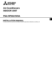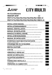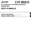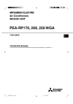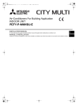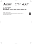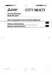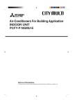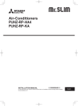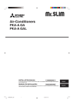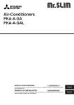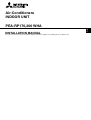
1
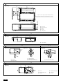
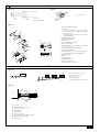
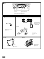
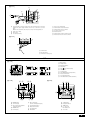
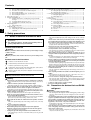
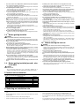
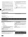
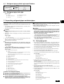
Air-Conditioners
INDOOR UNIT
GB
PEA-RP170,200 WHA
INSTALLATION
MANUAL
For safe and correct use, please read this installation manual thoroughly before installing the air-conditioner unit.
3
3.2
[Fig. 3.2.1]
800
1100
200~300
150~200
C
B
1350
1034
450
A
1100
37
23
more than 20
1250
1324
23
E
30 ±10
470
more than 100
more than 20
D
50
60
50
730
Keep the service space for the maintenance from
the bottom when the heat exchanger is cleaned.
A
4
A
Access door
B
Electrical parts box
C
Air inlet
D
Air outlet
E
Ceiling surface
A
Center of gravity
4.1
[Fig. 4.1.1]
1324
235
1034
494
701
A
5
5.1
[Fig. 5.1.1]
5.3
C
[Fig. 5.1.2]
[Fig. 5.3.1]
A
D
A
D
C
B
E
C
Nuts (field supply)
A
Unit body
D
Washers (accessory)
B
Lifting machine
E
M10 hanging bolt (field supply)
6
A
Indoor unit’s bottom surface
6.2
[Fig. 6.2.1]
D
B
100
244
52
C
30
165
A
E
2
424
F
A
Air inlet
B
Refrigerant piping (liquid)
C
Refrigerant piping (gas)
D
Control box
E
Drain pipe
F
Air outlet
7
7.1
[Fig. 7.1.1]
[Fig. 7.1.2]
A
A
A
Cut here
B
Remove brazed cap
Cool by a wet cloth
[Fig. 7.1.3]
A
A
Thermal insulation tubing (small)
B
Caution:
Pull out the thermal insulation on the refrigerant piping
at the site, braze the piping, and replace the insulation
in its original position.
B
C
Take care to ensure that condensation does not form on
exposed copper piping.
E
D
M
N
G
P
O
C
Refrigerant piping (liquid)
D
Refrigerant piping (gas)
E
Main body
F
Thermal insulation tubing (large)
G
Site refrigerant piping
H
Ensure that there are no gaps between the insulation
and the main body.
I
Thermal insulation tubing (small) (supplied) 1
J
Ties (large) (supplied) 4
K
Ensure that there is no gap here. Place join upwards.
L
Thermal insulation tubing (medium) (supplied) 2
M
Thermal insulation
N
Pull
O
Flared pipe end
P
Wrap with damp cloth
Q
Return to original position
R
Ensure that there is no gap here.
F
M
I
H
J
K
20
E
Q
20
R
L
K
20
J
20
7.2
[Fig. 7.2.1]
C
C
C
B Drain hose (Accessory)
E
A
B
A Downward slope 1/100 or more
C Indoor unit
1
D Collective piping
D
2
E Maximize this length to approx. 10 cm
[Fig. 7.2.2]
I
B
A
G
F
5
25
D
E
H
C
A Indoor unit
B Insulation pipe (short) (accessory)
C Tie band (accessory)
D Band fixing part
E Insertion margin
F Drain hose (accessory)
G Drain pipe (O.D. ø32 PVC TUBE, field supply)
H Insulating material (field supply)
I Max.145 ± 5 mm
3
8
[Fig. 8.0.1]
D
D
C
C
B
I
A
9
E
H
F
G
A
Air inlet
B
Air filter (supplied at site)
C
Duct
D
Canvas duct
E
Access door
F
Ceiling
G
Ensure sufficient length to prevent short cycling
H
Air outlet
I
Keep duct-work length 850 mm or more
9.1
9.2
[Fig. 9.1.1]
[Fig. 9.2.1]
B
A
S1 S2 S3
S1 S2 S3
1 2
TB4
A
TB15
B
A
Terminal block for indoor
transmission cable
B
Terminal block for outdoor
transmission cable
C
Remote controller
C
[Fig. 9.2.2]
B
C
2
A
Switch 16 A
B
Overcurrent protection 16 A
C
Indoor unit
D
A
1
S3
S2
S1
DC10~13V
L
C
N
A B
1 2
A
Non-polarized
B
TB15
C
Remote Controller
D
TB4
9.3
[Fig. 9.3.1]
[Fig. 9.3.2]
B
B
A
4
C
A
Screw holding cover (2pcs)
B
Cover
A
A
Terminal bed box
B
Knockout hole
C
Remove
[Fig. 9.3.3]
E
I
L
F
N
L
N
G
K
1
M
J
S1 S2 S3
L
2
H
S1 S2 S3
O
N
E
Use PG bushing to keep the weight of the cable and external force from being
applied to the power supply terminal connector. Use a cable tie to secure the
cable.
Wind the wire around the cable strap once to keep it from being pulled out.
F
Power source wiring
G
Tensile force
H
Use ordinary bushing
I
Power source terminal bed
J
Terminal bed for indoor transmission
K
Terminal bed for remote controller
L
To 1-phase power source
M
Transmission line
N
Terminal bed for outdoor transmission line
O
Transmission line to the remote controller
[Fig. 9.3.4]
S1
S2
A
S3
B
C
A
Terminal bed
B
Round terminal
C
Transmission cable (polar)
9.4
[Fig. 9.4.1]
1 Mode number
⁄
2
2 Setting number
⁄
3 4
3 Refrigerant address
⁄
4
4 Unit number
⁄
1
TEMP.
F
E
G
MENU
BACK
PAR-21MAA
MONITOR/SET
ON/OFF
ON/OFF
1
A
FILTER
DAY
CLOCK
2
Filter
B
TEST button
C
Set Time button
D
Timer On/Off button (Set Day button)
E
Mode selection button
F
Set temperature button
G
Timer Menu button (Monitor/Set button)
CHECK TEST
OPERATION
B
CLEAR
1
C
A
D
[Fig. 9.4.2]
F E
C
button (<Enter> button)
[Fig. 9.4.3]
D B
B
ED
TEST RUN
COOL, HEAT
˚C
˚C
˚C
SIMPLE
˚C
SIMPLE
TEMP.
MENU
ON/OFF
ON/OFF
A
FILTER
TEMP.
C
MENU
BACK
MONITOR/SET
DAY
CLOCK
OPERATION
A ON/OFF button
B Test run display
MONITOR/SET
FILTER
DAY
CHECK TEST
CLEAR
PAR-21MAA
HG
ON/OFF
CHECK TEST
BACK
PAR-21MAA
ON/OFF
CLOCK
OPERATION
I M
F Error code display
Test run remaining time display
CLEAR
A
A
CHECK button
B
Refrigerant address
C Indoor temperature liquid line
temperature display
G Set temperature button
C
TEMP. button
H Mode selection button
D
D ON/OFF lamp
I Fan speed button
IC: Indoor unit
OC: Outdoor unit
E Power display
M TEST button
E
Check code
5
GB
Contents
1. Safety precautions ......................................................................................
1.1. Before installation and electric work ..........................................
1.2. Precautions for devices that use R410A refrigerant ..................
1.3. Before getting installed ..............................................................
1.4. Before getting installed (moved) - electrical work ......................
1.5. Before starting the test run ........................................................
2. Indoor unit accessories ...............................................................................
3. Selecting an installation site .......................................................................
3.1. Install the indoor unit on a ceiling strong enough to sustain
its weight ....................................................................................
3.2. Securing installation and service space ....................................
3.3. Combining indoor units with outdoor units .................................
4. Fixing hanging bolts ....................................................................................
4.1 Fixing hanging bolts ...................................................................
5. Installing the unit .........................................................................................
5.1. Hanging the unit body ................................................................
5.2. Transporting the heat exchanger unit and the fan unit
separately ..................................................................................
6
6
6
7
7
7
7
7
8
8
8
8
8
8
8
8
5.3. Confirming the unit’s position and fixing hanging bolts .............. 8
6. Refrigerant pipe and drain pipe specifications ............................................ 8
6.1. Refrigerant pipe and drain pipe specifications ........................... 9
6.2. Refrigerant pipe, drain pipe ....................................................... 9
7. Connecting refrigerant pipes and drain pipes ............................................. 9
7.1. Refrigerant piping work .............................................................. 9
7.2. Drain piping work ....................................................................... 9
8. Duct work .................................................................................................. 10
9. Electrical wiring ......................................................................................... 10
9.1. Power supply wiring ................................................................. 10
9.2. Connecting remote controller, indoor and outdoor
transmission cables ................................................................. 10
9.3. Connecting electrical connections ........................................... 11
9.4. Function settings
(Function selection via the remote controller) .......................... 11
9.5. Before test run ......................................................................... 12
9.6. Test run .................................................................................... 12
9.7. Self-check ................................................................................ 12
1. Safety precautions
1.1. Before installation and electric work
D
s Before installing the unit, make sure you read all the “Safety
precautions”.
•
•
F
s The “Safety precautions” provide very important points regarding safety. Make sure you follow them.
Symbols used in the text
E
Warning:
Describes precautions that should be observed to prevent danger of injury
or death to the user.
•
•
•
I
Caution:
Describes precautions that should be observed to prevent damage to the
unit.
Symbols used in the illustrations
•
NL
: Indicates an action that must be avoided.
: Indicates that important instructions must be followed.
: Indicates a part which must be grounded.
P
: Indicates that caution should be taken with rotating parts. (This symbol is
displayed on the main unit label.) <Color: Yellow>
GR
: Beware of electric shock (This symbol is displayed on the main unit label.)
<Color: Yellow>
•
•
Warning:
Carefully read the labels affixed to the main unit.
RU
•
Warning:
TR
•
•
•
SV
•
HG
•
•
PO
CZ
•
•
•
Ask the dealer or an authorized technician to install the air conditioner.
- Improper installation by the user may result in water leakage, electric shock,
or fire.
Install the air unit at a place that can withstand its weight.
- Inadequate strength may cause the unit to fall down, resulting in injuries.
Use the specified cables for wiring. Make the connections securely so
that the outside force of the cable is not applied to the terminals.
- Inadequate connection and fastening may generate heat and cause a fire.
Prepare for typhoons and other strong winds and earthquakes and install the unit at the specified place.
- Improper installation may cause the unit to topple and result in injury.
Always use an air cleaner, humidifier, electric heater, and other accessories specified by Mitsubishi Electric.
- Ask an authorized technician to install the accessories. Improper installation
by the user may result in water leakage, electric shock, or fire.
Never repair the unit. If the air conditioner must be repaired, consult the
dealer.
- If the unit is repaired improperly, water leakage, electric shock, or fire may
result.
Do not touch the heat exchanger fins.
- Improper handling may result in injury.
When handling this product, always wear protective equipment.
EG: Gloves, full arm protection namely boiler suit, and safety glasses.
- Improper handling may result in injury.
If refrigerant gas leaks during installation work, ventilate the room.
- If the refrigerant gas comes into contact with a flame, poisonous gases will
be released.
6
•
•
Install the air conditioner according to this Installation Manual.
- If the unit is installed improperly, water leakage, electric shock, or fire may
result.
Have all electric work done by a licensed electrician according to “Electric Facility Engineering Standard” and “Interior Wire Regulations”and
the instructions given in this manual and always use a special circuit.
- If the power source capacity is inadequate or electric work is performed improperly, electric shock and fire may result.
Keep the electric parts away from water (washing water etc.).
- It might result in electric shock, catching fire or smoke.
Securely install the outdoor unit terminal cover (panel).
- If the terminal cover (panel) is not installed properly, dust or water may enter
the outdoor unit and fire or electric shock may result.
When installing and moving the air conditioner to another site, do not
charge the it with a refrigerant different from the refrigerant specified on
the unit.
- If a different refrigerant or air is mixed with the original refrigerant, the refrigerant cycle may malfunction and the unit may be damaged.
If the air conditioner is installed in a small room, measures must be taken
to prevent the refrigerant concentration from exceeding the safety limit
even if the refrigerant should leak.
- Consult the dealer regarding the appropriate measures to prevent the safety
limit from being exceeded. Should the refrigerant leak and cause the safety
limit to be exceeded, hazards due to lack of oxygen in the room could result.
When moving and reinstalling the air conditioner, consult the dealer or
an authorized technician.
- If the air conditioner is installed improperly, water leakage, electric shock, or
fire may result.
After completing installation work, make sure that refrigerant gas is not
leaking.
- If the refrigerant gas leaks and is exposed to a fan heater, stove, oven, or
other heat source, it may generate noxious gases.
Do not reconstruct or change the settings of the protection devices.
- If the pressure switch, thermal switch, or other protection device is shorted
and operated forcibly, or parts other than those specified by Mitsubishi Electric are used, fire or explosion may result.
To dispose of this product, consult your dealer.
Do not use a leak detection additive.
1.2. Precautions for devices that use R410A
refrigerant
Caution:
•
•
•
Do not use the existing refrigerant piping.
- The old refrigerant and refrigerator oil in the existing piping contains a large
amount of chlorine which may cause the refrigerator oil of the new unit to
deteriorate.
Use refrigerant piping made of C1220 (Cu-DHP) phosphorus deoxidized
copper as specified in the JIS H3300 “Copper and copper alloy seamless
pipes and tubes”. In addition, be sure that the inner and outer surfaces of
the pipes are clean and free of hazardous sulphur, oxides, dust/dirt, shaving particles, oils, moisture, or any other contaminant.
- Contaminants on the inside of the refrigerant piping may cause the refrigerant residual oil to deteriorate.
Store the piping to be used during installation indoors and keep both
ends of the piping sealed until just before brazing. (Store elbows and
other joints in a plastic bag.)
- If dust, dirt, or water enters the refrigerant cycle, deterioration of the oil and
compressor trouble may result.
1.3. Before getting installed
•
•
•
Caution:
•
•
•
•
•
•
Do not install the unit where combustible gas may leak.
- If the gas leaks and accumulates around the unit, an explosion may result.
Do not use the air conditioner where food, pets, plants, precision instruments, or artwork are kept.
- The quality of the food, etc. may deteriorate.
Do not use the air conditioner in special environments.
- Oil, steam, sulfuric smoke, etc. can significantly reduce the performance of
the air conditioner or damage its parts.
When installing the unit in a hospital, communication station, or similar
place, provide sufficient protection against noise.
- The inverter equipment, private power generator, high-frequency medical
equipment, or radio communication equipment may cause the air conditioner
to operate erroneously, or fail to operate. On the other hand, the air conditioner may affect such equipment by creating noise that disturbs medical
treatment or image broadcasting.
Do not install the unit on a structure that may cause leakage.
- When the room humidity exceeds 80% or when the drain pipe is clogged,
condensation may drip from the indoor unit. Perform collective drainage work
together with the outdoor unit, as required.
The indoor models should be installed the ceiling over than 2.5 m from
floor.
1.4. Before getting installed (moved) - electrical work
GB
•
D
•
•
F
•
•
1.5. Before starting the test run
Caution:
•
•
•
•
•
E
•
•
Turn on the power at least 12 hours before starting operation.
- Starting operation immediately after turning on the main power switch can
result in severe damage to internal parts. Keep the power switch turned on
during the operational season.
Do not touch the switches with wet fingers.
- Touching a switch with wet fingers can cause electric shock.
Do not touch the refrigerant pipes during and immediately after operation.
- During and immediately after operation, the refrigerant pipes are may be hot
and may be cold, depending on the condition of the refrigerant flowing through
the refrigerant piping, compressor, and other refrigerant cycle parts. Your
hands may suffer burns or frostbite if you touch the refrigerant pipes.
Do not operate the air conditioner with the panels and guards removed.
- Rotating, hot, or high-voltage parts can cause injuries.
Do not turn off the power immediately after stopping operation.
- Always wait at least five minutes before turning off the power. Otherwise,
water leakage and trouble may occur.
I
•
•
Install the power cable so that tension is not applied to the cable.
- Tension may cause the cable to break and generate heat and cause a fire.
Install an leak circuit breaker, as required.
- If an leak circuit breaker is not installed, electric shock may result.
Use power line cables of sufficient current carrying capacity and rating.
- Cables that are too small may leak, generate heat, and cause a fire.
Use only a circuit breaker and fuse of the specified capacity.
- A fuse or circuit breaker of a larger capacity or a steel or copper wire may
result in a general unit failure or fire.
Do not wash the air conditioner units.
- Washing them may cause an electric shock.
Be careful that the installation base is not damaged by long use.
- If the damage is left uncorrected, the unit may fall and cause personal injury
or property damage.
Install the drain piping according to this Installation Manual to ensure
proper drainage. Wrap thermal insulation around the pipes to prevent
condensation.
- Improper drain piping may cause water leakage and damage to furniture
and other possessions.
Be very careful about product transportation.
- Only one person should not carry the product if it weighs more than 20 kg.
- Some products use PP bands for packaging. Do not use any PP bands for a
means of transportation. It is dangerous.
- Do not touch the heat exchanger fins. Doing so may cut your fingers.
- When transporting the outdoor unit, suspend it at the specified positions on
the unit base. Also support the outdoor unit at four points so that it cannot
slip sideways.
Safely dispose of the packing materials.
- Packing materials, such as nails and other metal or wooden parts, may cause
stabs or other injuries.
- Tear apart and throw away plastic packaging bags so that children will not
play with them. If children play with a plastic bag which was not torn apart,
they face the risk of suffocation.
NL
•
•
P
•
Use ester oil, ether oil or alkylbenzene (small amount) as the refrigerator
oil to coat flares and flange connections.
- The refrigerator oil will degrade if it is mixed with a large amount of mineral oil.
Use liquid refrigerant to fill the system.
- If gas refrigerant is used to seal the system, the composition of the refrigerant in the cylinder will change and performance may drop.
Do not use a refrigerant other than R410A.
- If another refrigerant (R22, etc.) is used, the chlorine in the refrigerant may
cause the refrigerator oil to deteriorate.
Use a vacuum pump with a reverse flow check valve.
- The vacuum pump oil may flow back into the refrigerant cycle and cause the
refrigerator oil to deteriorate.
Do not use the following tools that are used with conventional refrigerants.
(Gauge manifold, charge hose, gas leak detector, reverse flow check valve,
refrigerant charge base, vacuum gauge, refrigerant recovery equipment)
- If the conventional refrigerant and refrigerator oil are mixed in the R410A,
the refrigerant may deteriorated.
- If water is mixed in the R410A, the refrigerator oil may deteriorate.
- Since R410A does not contain any chlorine, gas leak detectors for conventional refrigerants will not react to it.
Do not use a charging cylinder.
- Using a charging cylinder may cause the refrigerant to deteriorate.
Be especially careful when managing the tools.
- If dust, dirt, or water gets in the refrigerant cycle, the refrigerant may deteriorate.
GR
•
Caution:
RU
Ground the unit.
- Do not connect the ground wire to gas or water pipes, lightning rods, or
telephone ground lines. Improper grounding may result in electric shock.
TR
2. Indoor unit accessories
The unit is provided with the following accessories:
CZ
Quantity
1
1
1
2
5
1
8
1
SV
Accessories
Insulation pipe 25 mm small diameter
Insulation pipe 125 mm small diameter
Insulation pipe 120 mm large diameter
Tie band (small)
Tie band (large)
Drain hose
Washer
Wired remote controller
3. Selecting an installation site
•
•
Select a site with sturdy fixed surface sufficiently durable against the weight of
unit.
•
Select a site where refrigerant piping can easily be led to the outside.
•
Select a site which allows the supply air to be distributed fully in room.
Before installing unit, the routing to carry in unit to the installation site should
be determined.
•
Do not install unit at a site with oil splashing or steam in much quantity.
•
Do not install unit at a site where combustible gas may generate, flow in, stagnate or leak.
•
Do not install unit at a site where equipment generating high frequency waves
(a high frequency wave welder for example) is provided.
•
Select a site where the unit is not affected by entering air.
•
Select a site where the flow of supply and return air is not blocked.
7
HG
No.
1
2
3
4
5
6
7
8
PO
•
•
At a distance 1 m or more away from your TV and radio (to prevent picture from
being distorted or noise from being generated).
3.2. Securing installation and service space
•
In a place as far away as possible from fluorescent and incandescent lights (so
the infrared remote control can operate the air conditioner normally).
•
Select the optimum direction of supply airflow according to the configuration of
the room and the installation position.
•
Do not install unit at a site where fire detector is located at the supply air side.
(Fire detector may operate erroneously due to the heated air supplied during
heating operation.)
•
•
When special chemical product may scatter around such as site chemical plants
and hospitals, full investigation is required before installing unit. (The plastic
components may be damaged depending on the chemical product applied.)
As the piping and wiring are connected at the bottom and side surfaces, and
the maintenance is made at the same surfaces, allow a proper space properly.
For the efficient suspension work and safety, provide a space as much as
possible.
•
GB
•
[Fig. 3.2.1] (P.2)
If the unit is run for long hours when the air above the ceiling is at high temperature/high humidity (due point above 26 °C), due condensation may be
produced in the indoor unit. When operating the units in this condition, add
insulation material (10-20 mm) to the entire surface of the indoor unit to avoid
due condensation.
A
Access door
B
Electrical parts box
C
Air inlet
D
Air outlet
E
Ceiling surface
3.3. Combining indoor units with outdoor
units
Do not install the unit where ambient temperature exceeds 35°C [95°F] DB.
For combining indoor units with outdoor units, refer to the outdoor unit installation
manual.
3.1. Install the indoor unit on a ceiling strong
enough to sustain its weight
Warning:
D
The unit must be securely installed on a structure that can sustain its weight.
If the unit is mounted on an unstable structure, it may fall down causing
injuries.
4. Fixing hanging bolts
F
4.1
[Fig. 4.1.1] (P.2)
A
E
•
Fixing hanging bolts
If necessary, reinforce the hanging bolts with anti-quake supporting members
as countermeasures against earthquakes.
* Use M10 for hanging bolts and anti-quake supporting members (field supply).
Center of gravity
(Give site of suspension strong structure.)
Hanging structure
Ceiling: The ceiling structure varies from building to one another. For detailed
information, consult your construction company.
I
•
Center of gravity and Product Weight
NL
Model name
PEA-RP170WHA
PEA-RP200WHA
W
1034
1034
L
1324
1324
Y
701
701
X
494
494
Z
235
235
Product Weight (kg)
108
108
P
5. Installing the unit
GR
5.1. Hanging the unit body
s Bring the indoor unit to an installation site as it is packed.
s To hang the indoor unit, use a lifting machine to lift and pass through the
hanging bolts.
A
Unit body
B
Lifting machine
[Fig. 5.1.2] (P.2)
TR
RU
[Fig. 5.1.1] (P.2)
C
Nuts (field supply)
D
Washers (accessory)
E
M10 hanging bolt (field supply)
5.3. Confirming the unit’s position and fixing hanging bolts
s Use the gage supplied with the panel to confirm that the unit body and
hanging bolts are positioned in place. If they are not positioned in place,
it may result in dew drops due to wind leak. Be sure to check the positional
relationship.
s Use a level to check that the surface indicated by A is at level. Ensure
that the hanging bolt nuts are tightened to fix the hanging bolts.
s To ensure that drain is discharged, be sure to hang the unit at level using
a level.
[Fig. 5.3.1] (P.2)
A
5.2. Transporting the heat exchanger unit
and the fan unit separately
Indoor unit’s bottom surface
Caution:
Install the unit in horizontal position. If the side with drain port is installed
higher, water leakage may be caused.
PO
HG
SV
CZ
s Refer to the “Manipulation Details” label on the unit for how to separate
the heat exchanger unit and the fan unit.
Caution:
Heat exchanger unit and the fan unit cannot be installed in separate locations. Doing so will cause water leakage.
6. Refrigerant pipe and drain pipe specifications
To avoid dew drops, provide sufficient antisweating and insulating work to the refrigerant and drain pipes.
When using commercially available refrigerant pipes, be sure to wind commercially available insulating material (with a heat-resisting temperature of more than
100 °C and thickness given below) onto both liquid and gas pipes.
Insulate all indoor pipes with form polyethylene insulation with a minimum density
of 0.03 and a thickness as specified in the table below.
1 Select the thickness of insulating material by pipe size.
Pipe size
6.4 mm to 25.4 mm
28.6 mm to 38.1 mm
Insulating material’s thickness
More than 10 mm
More than 15 mm
2 If the unit is used on the highest story of a building and under conditions of
high temperature and humidity, it is necessary to use pipe size and insulating
material’s thickness more than those given in the table above.
3 If there are customer’s specifications, simply follow them.
8
6.1. Refrigerant pipe and drain pipe specifications
Model
170·200
Item
Refrigerant pipe
(Brazing connection)
Liquid pipe
Gas pipe
ø 9.52
ø 25.4
O.D. ø 32
Drain pipe
6.2. Refrigerant pipe, drain pipe
[Fig. 6.2.1] (P.2)
Air outlet
7.1. Refrigerant piping work
Caution:
•
Caution:
•
Install the refrigerant piping for the indoor unit in accordance with the
following.
1. Cut the tip of the indoor unit piping, remove the gas, and then remove the
brazed cap.
•
[Fig. 7.1.1] (P.3)
Cut here
B
Remove brazed cap
2. Pull out the thermal insulation on the site refrigerant piping, braze the unit
piping, and replace the insulation in its original position.
Wrap the piping with insulating tape.
Note:
• When blazing the refrigerant pipes, be sure to blaze, after covering a wet
cloth to the pipes of the units in order to prevent it from burning and
shrinking by heat.
•
7.2. Drain piping work
•
Ensure that the drain piping is downward (pitch of more than 1/100) to the
outdoor (discharge) side. Do not provide any trap or irregularity on the way.
•
Ensure that any cross-wise drain piping is less than 20 m (excluding the difference of elevation). If the drain piping is long, provide metal braces to prevent it
from waving. Never provide any air vent pipe. Otherwise drain may be ejected.
•
Use a hard vinyl chloride pipe O.D. ø32 for drain piping.
•
Ensure that collected pipes are 10 cm lower than the unit body’s drain port.
[Fig. 7.1.2] (P.3)
A
•
Cool by a wet cloth
Pay strict attention when wrapping the copper piping since wrapping the
piping may cause condensation instead of preventing it.
[Fig. 7.1.3] (P.3)
A
B
Thermal insulation tubing (small)
Caution:
Pull out the thermal insulation on the refrigerant piping at the site, braze the piping, and replace the insulation in its original position.
Use refrigerant piping made of C1220 (Cu-DHP) phosphorus deoxidized
copper as specified in the JIS H3300 “Copper and copper alloy seamless
pipes and tubes”. In addition, be sure that the inner and outer surfaces of
the pipes are clean and free of hazardous sulphur, oxides, dust/dirt, shaving particles, oils, moisture, or any other contaminant.
Never use existing refrigerant piping.
- The large amount of chlorine in conventional refrigerant and refrigerator oil
in the existing piping will cause the new refrigerant to deteriorate.
Store the piping to be used during installation indoors and keep both
ends of the piping sealed until just before brazing.
- If dust, dirt, or water gets into the refrigerant cycle, the oil will deteriorate and
the compressor may fail.
I
A
•
Do not provide any odor trap at the drain discharge port.
•
Put the end of the drain piping in a position where no odor is generated.
•
Do not put the end of the drain piping in any drain where ionic gases are generated.
[Fig. 7.2.1] (P.3)
Take care to ensure that condensation does not form on exposed copper piping.
A
Downward slope 1/100 or more
C
Refrigerant piping (liquid)
B
Drain hose (Accessory)
D
Refrigerant piping (gas)
C
Indoor unit
E
Main body
D
Collective piping
F
Thermal insulation tubing (large)
E
Maximize this length to approx. 10 cm
G
Site refrigerant piping
H
Ensure that there are no gaps between the insulation and the main body.
I
Thermal insulation tubing (small) (supplied) 1
J
Ties (large) (supplied) 4
K
Ensure that there is no gap here. Place join upwards.
L
Thermal insulation tubing (medium) (supplied) 2
M
Thermal insulation
N
Pull
O
Flared pipe end
P
Wrap with damp cloth
Q
Return to original position
R
Ensure that there is no gap here.
Cautions On Refrigerant Piping
s Be sure to use non-oxidative brazing for brazing to ensure that no foreign matter or moisture enter into the pipe.
s Be sure to apply refrigerating machine oil over the flare connection seating surface and tighten the connection using a double spanner.
s Provide a metal brace to support the refrigerant pipe so that no load is
imparted to the indoor unit end pipe. This metal brace should be provided 50 cm away from the indoor unit’s flare connection.
D
The method of pipe connection is brazing connection.
P
•
RU
For constraints on pipe length and allowable difference of elevation, refer to
the outdoor unit manual.
1. Insert the drain hose (accessory) into the drain port.
(The drain hose must not be bent more than 45° to prevent the hose from
breaking or clogging.)
The connecting part between the indoor unit and the drain hose may be disconnected at the maintenance. Fix the part with the accessory band, not be
adhered.
2. Attach the drain pipe (O.D. ø32 PVC TUBE, field supply).
(Attach the pipe with glue for the hard vinyl chloride pipe, and fix it with the
band (small, accessory).)
3. Perform insulation work on the drain pipe (O.D. ø32 PVC TUBE) and on the
socket (including elbow).
[Fig. 7.2.2] (P.3)
A
Indoor unit
B
Insulation pipe (short) (accessory)
C
Tie band (accessory)
D
Band fixing part
E
Insertion margin
F
Drain hose (accessory)
G
Drain pipe (O.D. ø32 PVC TUBE, field supply)
H
Insulating material (field supply)
I
Max.145 ± 5 mm
HG
•
Warning:
When installing and moving the unit, do not charge it with refrigerant other
than the refrigerant specified on the unit.
- Mixing of a different refrigerant, air, etc. may cause the refrigerant cycle to malfunction and result in severe damage.
PO
This piping work must be done in accordance with the installation manuals for both
outdoor unit.
GB
7. Connecting refrigerant pipes and drain pipes
F
F
E
Drain pipe
NL
Control box
E
GR
Refrigerant piping (liquid)
D
TR
B
Refrigerant piping (gas)
CZ
Air inlet
C
SV
A
9
8. Duct work
•
When connecting ducts, insert a canvas duct between the main body and the
duct.
A
Air inlet
B
Air filter (supplied at site)
•
Use non-combustible duct components.
C
Duct
D
Canvas duct
•
Install sufficient thermal insulation to prevent condensation forming on outlet
duct flanges and outlet ducts.
E
Access door
F
Ceiling
G
Ensure sufficient length to prevent short cycling
H
Air outlet
[Fig. 8.0.1] (P.4)
I
Keep duct-work length 850 mm or more
Caution:
•
Keep the distance between the inlet grille and the fan over 850 mm.
If it is less than 850 mm, install a safety guard not to touch the fan.
9. Electrical wiring
GB
Precautions on electrical wiring
Warning:
Electrical work should be done by qualified electrical engineers in accordance with “Engineering Standards For Electrical Installation” and supplied
installation manuals. Special circuits should also be used. If the power circuit lacks capacity or has an installation failure, it may cause a risk of electric shock or fire.
D
1. Be sure to install an earth leakage breaker to the power.
2. Install the unit to prevent that any of the control circuit cables (remote controller, transmission cables) is brought in direct contact with the power cable outside the unit.
E
F
3. Ensure that there is no slack on all wire connections.
4. Some cables (power, remote controller, transmission cables) above the ceiling
may be bitten by mouses. Use as many metal pipes as possible to insert the
cables into them for protection.
5. Never connect the power cable to leads for the transmission cables. Otherwise
the cables would be broken.
Caution:
Be sure to put the unit to the ground on the outdoor unit side. Do not connect the earth cable to any gas pipe, water pipe, lightening rod, or telephone
earth cable. Incomplete grounding may cause a risk of electric shock.
Types of control cables
1. Wiring transmission cables
Note:
• Transmission cables shall not be lighter than polychloroprene sheathed
flexible cord. (Design 245 IEC 57)
•
•
Less than 80 m.
•
I
Cable diameter
0.3 to 1.25 mm2
Length
Less than 500 m
GR
Sheathed 2-core cable (unshielded) CVV
Power supply cords of appliances shall not be lighter than design 245 IEC 57
or 227 IEC 57.
RU
P
NL
Circuit rating
S1 - S2: 230V AC
S2 - S3: 24V DC
* The figures are not always against the ground.
S3 terminal has 24V DC against S2 terminal. However between S3 and S1, these
terminals are not electrically insulated by the transformer or other device.
MA remote controller
Types of cables
•
•
A switch with at least 3 mm contact separation in each pole shall be provided
by the Air conditioner installation.
Power cable size: more than 2.0 mm2
TR
[Fig. 9.1.1] (P.4)
A
Switch 16 A
C
Indoor unit
B
Overcurrent protection 16 A
[Selecting non-fuse breaker (NF) or earth leakage breaker (NV)]
To select NF or NV instead of a combination of Class B fuse with switch, use the
following:
In the case of Class B fuse rated 15 A or 20 A,
NF model name (MITSUBISHI): NF30-CS (15 A) (20 A)
NV model name (MITSUBISHI): NV30-CA (15 A) (20 A)
Use an earth leakage breaker with a sensitivity of less than 30 mA 0.1 s.
9.2. Connecting remote controller, indoor
and outdoor transmission cables
Warning:
• The compressor will not operate unless the indoor/outdoor transmission
phase connection is correct.
• The connection wiring between the outdoor and indoor units can be extended up to a maximum of 50 meters, and the total extension including
the crossover wiring between rooms is a maximum of 80 m.
•
Cable 3-core 1.5 mm2, in conformity with design 245 IEC 57.
Install a remote controller following the manual supplied with the remote controller.
•
Connect the “1” and “2” on indoor unit TB15 to a MA remote controller. (Nonpolarized 2-wire)
•
Connect the remote controller’s transmission cable within 10 m using a 0.75 mm2
core cable. If the distance is more than 10 m, use a 1.25 mm2 junction cable.
Caution:
[Fig. 9.2.1] (P.4) MA Remote controller
Do not use anything other than the correct capacity breaker and fuse. Using
fuse, wire or copper wire with too large capacity may cause a risk of malfunction or fire.
•
HG
Connect indoor unit TB4 and terminal block for indoor-outdoor transmission
line. (polar 3-core)
•
•
CZ
Cable length
2. Remote controller cables
9.1. Power supply wiring
SV
Cable diameter
More than 1.5 mm2
•
6. Be sure to connect control cables to the indoor unit, remote controller, and the
outdoor unit.
7. Put the unit to the ground on the outdoor unit side.
Types of transmission cables
Design wiring in accordance with the following table <Table 1>.
A
Terminal block for indoor transmission cable
B
Terminal block for outdoor transmission cable
C
Remote controller
DC 9 to 13 V between 1 and 2 (MA remote controller)
PO
[Fig. 9.2.2] (P.4) MA Remote controller
10
A
Non-polarized
B
TB15
C
Remote Controller
D
TB4
Caution:
Install wiring so that it is not tight and under tension. Wiring under tension
may break, or overheat and burn.
9.4. Function settings (Function selection
via the remote controller)
9.3. Connecting electrical connections
9.4.1
Please identify the model name of the operation manual attached on the terminal
bed box cover with that shown on the rating name plate.
1. Remove the screw (2pcs) holding the cover to dismount the cover.
B
Cover
2. Open knockout holes
(Recommend to use a screwdriver or the like for this work.)
[Fig. 9.3.2] (P.4)
B
Knockout hole
2 Use the C button to set the refrigerant address (3) to 00.
[Fig. 9.3.3] (P.5)
E
Use PG bushing to keep the weight of the cable and external force from being
applied to the power supply terminal connector. Use a cable tie to secure the
cable.
Wind the wire around the cable strap once to keep it from being pulled out.
F
Power source wiring
H
Use ordinary bushing
I
K
M
Transmission line
N
Terminal bed for outdoor transmission line
O
Transmission line to the remote controller
G
Tensile force
Power source terminal bed
J
Terminal bed for indoor transmission
Terminal bed for remote controller
L
To 1-phase power source
[Fig. 9.3.4] (P.5)
Terminal bed
C
Transmission cable (polar)
B
Round terminal
5. After wiring is complete, make sure again that there is no slack on the connections, and attach the cover onto the terminal bed box in the reverse order of
removal.
6 Press the F buttons to set the mode number (1) to 08.
7 Press the G button and the current set setting number (2) will flash.
Use the F button to switch the setting number in response to the external
static pressure to be used.
External static
pressure
60 Pa
75 Pa
100 Pa
150 Pa (before shipment)
Setting no. of mode
no. 08
1
2
3
1
Setting no. of mode
no. 10
2
2
2
1
9 Press the FILTER A and TEST RUN B buttons simultaneously for at least two
seconds. The function selection screen will disappear momentarily and the air
conditioner OFF display will appear.
2) Other functions
1 Select unit number 00 for the settings. (Settings for all indoor units)
Refer to Function table 1.
2 Select unit number 01 to 04 or AL for the settings. (Settings for each indoor
unit)
To set the indoor unit in the individual system, select unit number 01.
To set each indoor unit of two, three or four indoor units, which are connected
when these units are simultaneously in operation, select unit number 01 to 04.
To set all indoor units of two, three or four indoor units which are connected
when these units are simultaneously in operation, select AL.
Refer to Function table 2.
RU
Notes:
• Do not pinch the cables or wires when attaching the terminal bed box
cover. Doing so may cause a risk of disconnection.
• When accommodating the terminal bed box, make sure that the connectors on the box side are not removed. If removed, it cannot operate normally.
Function table 1
Select unit number 00
LOSSNAY connectivity
Mode no.
01
02
03
Setting no. Initial setting
1
2
1
2
3
1
2
3
Check
Setting no. Initial setting
1
2
3
Check
TR
Settings
Not available
Available
Indoor unit operating average
Set by indoor unit’s remote controller
Remote controller’s internal sensor
Not Supported
Supported (indoor unit is not equipped with outdoor-air intake)
Supported (indoor unit is equipped with outdoor-air intake)
CZ
Mode
Power failure automatic recovery*1
(AUTO RESTART FUNCTION)
Indoor temperature detecting
Settings
100 Hr
2500 Hr
No filter sign indicator
Mode no.
07
SV
Function table 2
Select unit numbers 01 to 04 or all units (AL [wired remote controller]/07 [wireless remote controller])
Mode
Filter sign
GB
5 Press the E MODE button to designate the refrigerant address/unit number.
[--] will flash in the mode number (1) display momentarily.
8 Press the MODE button E and mode and the setting number (1) and (2) will
change to being on constantly and the contents of the setting can be confirmed.
[Transmission cable connection]
A
4 Use the C button to set the unit number (4) to 01-04 or AL.
D
4. Connect the power source, Earth, transmission and remote controller wiring.
The dismounting of the terminal bed box is not needed.
3 Press D and [--] will start to flash in the unit number (4) display.
F
3. Fix power source wiring to terminal bed box by using buffer bushing for tensile
force. (PG connection or the like.) Connect transmission wiring to transmission
terminal bed through the knockout hole of terminal bed box using ordinary
bushing.
E
Remove
I
Terminal bed box
C
1 Go to the function setting mode.
Switch OFF the remote controller.
Press the A and B buttons simultaneously and hold them for at least
2 seconds. FUNCTION will start to flash.
NL
A
Be sure to change the external static pressure setting depending on the duct
and the grill used.
P
Screw holding cover (2pcs)
GR
A
1) Changing the external static pressure setting [Fig. 9.4.1] (P.5)
•
[Fig. 9.3.1] (P.4)
Function setting on the unit (Selecting the unit
functions)
or other mark in the
PO
Note: When the function of an indoor unit were changed by function selection after the end of installation, always indicate the contents by entering a
appropriate check filed of the tables.
HG
*1 When the power supply returns, the air conditioner will start 3 minutes later.
11
9.5. Before test run
9.6. Test run
s After completing installation and the wiring and piping of the indoor and
outdoor units, check for refrigerant leakage, looseness in the power supply or control wiring, wrong polarity, and no disconnection of one phase
in the supply.
s Use a 500-volt megohmmeter to check that the resistance between the
Ω.
power supply terminals and ground is at least 1.0 MΩ
s Do not carry out this test on the control wiring (low voltage circuit) terminals.
9.6.1.
Warning:
F
D
GB
Ω.
Do not use the air conditioner if the insulation resistance is less than 1.0 MΩ
Insulation resistance
After installation or after the power source to the unit has been cut for an extended
period, the insulation resistance will drop below 1 MΩ due to refrigerant accumulating in the compressor. This is not a malfunction. Perform the following procedures.
E
5
6
7
8
1. Remove the wires from the compressor and measure the insulation resistance
of the compressor.
Turn on the power at least 12 hours before the test run.
Press the [TEST] button twice. ➡ “TEST RUN” liquid crystal display
Press the [Mode selection] button. ➡ Make sure that wind is blown out.
Press the [Mode selection] button and switch to the cooling (or heating) mode.
➡ Make sure that cold (or warm) wind is blown out.
Press the [Fan speed] button. ➡ Make sure that the wind speed is switched.
Check operation of the outdoor unit fan.
Release test run by pressing the [ON/OFF] button. ➡ Stop
Register a telephone number.
The telephone number of the repair shop, sales office, etc., to contact if an
error occurs can be registered in the remote controller. The telephone number
will be displayed when an error occurs. For registration procedures, refer to the
operation manual for the indoor unit.
[Fig. 9.4.2] (P.5)
A
B
C
D
E
F
2. If the insulation resistance is below 1 MΩ, the compressor is faulty or the resistance dropped due the accumulation of refrigerant in the compressor.
3. After connecting the wires to the compressor, the compressor will start to warm
up after power is supplied. After supplying power for the times indicated below,
measure the insulation resistance again.
• The insulation resistance drops due to accumulation of refrigerant in the
compressor. The resistance will rise above 1 MΩ after the compressor is
warmed up for two to three hours.
(The time necessary to warm up the compressor varies according to atmospheric conditions and refrigerant accumulation.)
• To operate the compressor with refrigerant accumulated in the compressor,
the compressor must be warmed up at least 12 hours to prevent breakdown.
4. If the insulation resistance rises above 1 MΩ, the compressor is not faulty.
Caution:
•
The compressor will not operate unless the indoor/outdoor transmission
phase connection is correct.
•
Turn on the power at least 12 hours before starting operation.
-
Starting operation immediately after turning on the main power switch can
result in severe damage to internal parts. Keep the power switch turned on
during the operational season.
NL
I
1
2
3
4
Using wired remote controller
G
H
I
M
9.7. Self-check
9.7.1.
1
2
3
4
Wired remote controller
Turn on the power.
Press the [CHECK] button twice.
Set refrigerant address with [TEMP] button if system control is used.
Press the [ON/OFF] button to stop the self-check.
[Fig. 9.4.3] (P.5)
A
B
C
D
PO
HG
SV
CZ
TR
RU
GR
P
E
•
ON/OFF button
Test run display
Indoor temperature liquid line temperature display
ON/OFF lamp
Power display
Error code display
Test run remaining time display
Set temperature button
Mode selection button
Fan speed button
TEST button
CHECK button
Refrigerant address
TEMP. button
IC: Indoor unit
OC: Outdoor unit
Check code
For description of each check code, refer to the following table.
1 Check code
P1
P2, P9
E6, E7
P4
P5
PA
Pb
P6
EE
P8
E4
Fb
E0, E3
E1, E2
E9
UP
U3, U4
UF
U2
U1, Ud
U5
U8
U6
U7
U9, UH
Symptom
Intake sensor error
Pipe (Liquid or 2-phase pipe) sensor error
Indoor/outdoor unit communication error
Drain sensor error
Drain pump error
Forced compressor error
Fan controller error
Freezing/Overheating safeguard operation
Communication error between indoor and outdoor units
Pipe temperature error
Remote controller signal receiving error
Indoor unit control system error (memory error, etc.)
Remote controller transmission error
Remote controller control board error
Indoor/outdoor unit communication error (Transmitting error) (Outdoor unit)
Compressor overcurrent interruption
Open/short of outdoor unit thermistors
Compressor overcurrent interruption (When compressor locked)
Abnormal high discharging temperature/49C worked/insufficient refrigerant
Abnormal high pressure (63H worked)/Overheating safeguard operation
Abnormal temperature of heat sink
Outdoor unit fan safeguard stop
Compressor overcurrent interruption/Abnormal of power module
Abnormality of super heat due to low discharge temperature
Abnormality such as overvoltage or voltage shortage and abnormal synchronous signal to main circuit/
Current sensor error
Others
Other errors (Refer to the technical manual for the outdoor unit.)
• On wired remote controller
1 Check code displayed in the LCD.
12
Remark
For details, check the LED display
of the outdoor controller board.
This product is designed and intended for use in the residential, commercial and light-industrial environment.
The product at hand is
based on the following
EU regulations:
•
•
Low Voltage Directive 2006/95/EC
Electromagnetic Compatibility Directive
2004/108/EC
Please be sure to put the contact address/telephone number on
this manual before handing it to the customer.
HEAD OFFICE: TOKYO BLDG., 2-7-3, MARUNOUCHI, CHIYODA-KU, TOKYO 100-8310, JAPAN
Authorized representative in EU: MITSUBISHI ELECTRIC EUROPE B.V.
HARMAN HOUSE, 1 GEORGE STREET, UXBRIDGE, MIDDLESEX UB8 1QQ, U.K.
WT05749X01