1
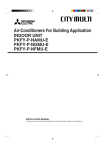
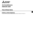
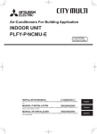
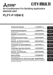
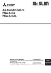
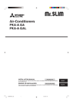
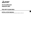
Air-Conditioners For Building Application
INDOOR UNIT
PLFY-P·NAMU-E
INSTALLATION MANUAL
For safe and correct use, please read this installation manual thoroughly before installing the air-conditioner unit.
Contents
1.
2.
3.
4.
Safety precautions ...................................................................................
Installation location ..................................................................................
Installing the indoor unit ...........................................................................
Installing the refrigerant piping .................................................................
2
3
3
5
5.
6.
7.
8.
Drainage piping work ............................................................................... 6
Electrical work .......................................................................................... 7
Test run .................................................................................................... 9
Installing the grille .................................................................................. 10
1. Safety precautions
s Before installing the unit, make sure you read all the “Safety precautions”.
s Please report to your supply authority or obtain their consent before
connecting this equipment to the power supply system.
Warning:
Describes precautions that must be observed to prevent danger of injury or
death to the user.
Caution:
Describes precautions that must be observed to prevent damage to the unit.
Warning:
• Ask a dealer or an authorized technician to install the unit.
• For installation work, follow the instructions in the Installation Manual and use
tools and pipe components specifically made for use with refrigerant specified
in the outdoor unit installation manual.
• The unit must be installed according to the instructions in order to minimize
the risk of damage from earthquakes, typhoons, or strong winds. An incorrectly installed unit may fall down and cause damage or injuries.
• The unit must be securely installed on a structure that can sustain its weight.
• If the air conditioner is installed in a small room, measures must be taken to
prevent the refrigerant concentration in the room from exceeding the safety
limit in the event of refrigerant leakage. Should the refrigerant leak and cause
the concentration limit to be exceeded, hazards due to lack of oxygen in the
room may result.
After installation work has been completed, explain the “Safety Precautions,” use,
and maintenance of the unit to the customer according to the information in the Operation Manual and perform the test run to ensure normal operation. Both the Installation Manual and Operation Manual must be given to the user for keeping. These
manuals must be passed on to subsequent users.
: Indicates a part which must be grounded.
Warning:
Carefully read the labels affixed to the main unit.
• Ventilate the room if refrigerant leaks during operation. If refrigerant comes
into contact with a flame, poisonous gases will be released.
• All electric work must be performed by a qualified technician according to
local regulations and the instructions given in this manual.
• Use only specified cables for wiring.
• The terminal block cover panel of the unit must be firmly attached.
• Use only accessories authorized by Mitsubishi Electric and ask a dealer or
an authorized technician to install them.
• The user should never attempt to repair the unit or transfer it to another location.
• After installation has been completed, check for refrigerant leaks. If refrigerant leaks into the room and comes into contact with the flame of a heater or
portable cooking range, poisonous gases will be released.
1.1. Before installation (Euvironment)
Caution:
• Do not use the unit in an unusual environment. If the air conditioner is installed in areas exposed to steam, volatile oil (including machine oil), or sulfuric
gas, areas exposed to high salt content such as the seaside, the performance
can be significantly reduced and the internal parts can be damaged.
• Do not install the unit where combustible gases may leak, be produced, flow,
or accumulate. If combustible gas accumulates around the unit, fire or explosion may result.
• Do not keep food, plants, caged pets, artwork, or precision instruments in the
direct airflow of the indoor unit or too close to the unit, as these items can be
damaged by temperature changes or dripping water.
• When the room humidity exceeds 80% or when the drainpipe is clogged, water may drip from the indoor unit. Do not install the indoor unit where such
dripping can cause damage.
• When installing the unit in a hospital or communications office, be prepared
for noise and electronic interference. Inverters, home appliances, high-frequency medical equipment, and radio communications equipment can cause
the air conditioner to malfunction or breakdown. The air conditioner may also
affect medical equipment, disturbing medical care, and communications equipment, harming the screen display quality.
1.2. Before installation or relocation
Caution:
• Be extremely careful when transporting the units. Two or more persons are
needed to handle the unit, as it weighs 44 lbs. (20 kg) or more. Do not grasp
the packaging bands. Wear protective gloves as you can injure your hands
on the fins or other parts.
• Be sure to safely dispose of the packaging materials. Packaging materials,
such as nails and other metal or wooden parts may cause stabs or other
injuries.
• Thermal insulation of the refrigerant pipe is necessary to prevent condensation. If the refrigerant pipe is not properly insulated, condensation will be formed.
• Place thermal insulation on the pipes to prevent condensation. If the drainpipe is installed incorrectly, water leakage and damage to the ceiling, floor,
furniture, or other possessions may result.
• Do not clean the air conditioner unit with water. Electric shock may result.
• Tighten all flare nuts to specification using a torque wrench. If tightened too
much, the flare nut can break after an extended period.
1.3. Before electric work
Caution:
• Be sure to install circuit breakers. If not installed, electric shock may result.
• For the power lines, use standard cables of sufficient capacity. Otherwise, a
short circuit, overheating, or fire may result.
• When installing the power lines, do not apply tension to the cables.
• Be sure to ground the unit. If the unit is not properly grounded, electric shock
may result.
• Use circuit breakers (ground fault interrupter, isolating switch (+B fuse), and
molded case circuit breaker) with the specified capacity. If the circuit breaker
capacity is larger than the specified capacity, breakdown or fire may result.
1.4. Before starting the test run
Caution:
• Turn on the main power switch more than 12 hours before starting operation.
Starting operation just after turning on the power switch can severely damage the internal parts.
• Before starting operation, check that all panels, guards and other protective
parts are correctly installed. Rotating, hot, or high voltage parts can cause
injuries.
2
• Do not operate the air conditioner without the air filter set in place. If the air
filter is not installed, dust may accumulate and breakdown may result.
• Do not touch any switch with wet hands. Electric shock may result.
• Do not touch the refrigerant pipes with bare hands during operation.
• After stopping operation, be sure to wait at least five minutes before turning off
the main power switch. Otherwise, water leakage or breakdown may result.
2. Installation location
Refer to the outdoor unit installation manual.
3. Installing the indoor unit
1
3.1. Check the indoor unit accessories (Fig. 3-1)
2
3
The indoor unit should be supplied with the following accessories.
5
6
7
Accessory name
Installation template
Washers (with insulation)
Washers (without insulation)
Pipe cover (for refrigerant piping joint)
Small diameter
Large diameter
Band (large)
Band (small)
Screw with washer (M5 × 25) for mounting grille
Drain socket
Insulation
8
Flare nut
1
2
4
3
4
5
6
P18
P36
7
Q’ty
1
4
4
1
1
6
2
4
1
1
2 <ø3/8"(9.52),
ø5/8" (15.88)>
1 <ø3/4" (19.05)>
8
Fig. 3-1
3.2. Ceiling openings and suspension bolt installation
locations (Fig. 3-2)
37-3/8 (950) D
25/32 (20) to 1-25/32 (45)
33-27/32 (860) to 35-13/16 (910) C
25/32 (20) to 1-25/32 (45)
• Using the installation template (top of the package) and the gauge (supplied as an
accessory with the grille), make an opening in the ceiling so that the main unit can
be installed as shown in the diagram. (The method for using the template and the
gauge are shown.)
* Before using, check the dimensions of template and gauge, because they change
due to fluctuations of temperature and humidity.
* The dimensions of ceiling opening can be regulated within the range shown in
following diagram; so center the main unit against the opening of ceiling, ensuring that the respective opposite sides on all sides of the clearance between
them becomes identical.
• Use M10 (3/8") suspension bolts.
* Suspension bolts are to be procured at the field.
• Install securely, ensuring that there is no clearance between the ceiling panel &
grille, and between the main unit & grille.
23-13/16 (605) B
6-1/4
(159)
7-3/4
(197)
33-27/32 (860) to 35-13/16 (910) C
6-1/4 (159)
7-9/16 (192)
3-27/32 (98)
37-3/8 (950) D
33-1/16 (840) A
31-7/8 (810) B
6-1/4 (159)
6-1/4
(159)
11/16 +3/16 (17 +50 )
0
F
E
C
∗D
∗1-15/16 (50)
to 2-3/4 (70)
∗4-1/8
(105)
F
1-3/16
(30)
E
Min. 40 (1000)
G
11/16 +3/16 (17 +5
0)
0
5-5/16 (135)
33-1/16 (840) A
Min. 20 (500)
H
1(26)
B
A
7-9/16(98)
G
A
2-3/8
(60)
11-1/4
(286)
F 14-23/32
Outer side of main unit
Bolt pitch
Ceiling opening
Outer side of Grille
Grille
Ceiling
Multi function casement (option)
Entire periphery
Note that the space between ceiling panel of the unit and ceiling slab and etc must be 3/8 in.
(10 mm) to 9/16 in. (15 mm).
in. (mm)
Models
P12, P15, P18, P24
P30, P36
Fig. 3-2
ED
A
B
C
D
E
F
G
H
*
A
(374)
A
B
C
D
E
F
G
Drain pipe
Ceiling
Grille
Refrigerant pipe (liquid)
Refrigerant pipe (gas)
Water supply inlet
Main unit
C
9-1/2 (241)
11-1/16 (281)
D
10-3/16 (258)
11-3/4 (298)
3.3. Refrigerant and drainage piping locations of indoor
unit
The figure marked with * in the drawing represent the dimensions of the main unit
excluding those of the optional multi function casement. (Fig. 3-3)
• When the optional multi-functional casement is installed, add 5-5/16 in. (135 mm)
to the dimensions marked on the figure.
∗6-11/16
(170)
∗5-1/2
(140)
∗7-15/32
(190)
in. (mm)
B
C
Models
P12, P15
P18, P24, P30
P36
A
3 (76)
3-5/32 (80)
3-5/16 (84)
B
3-11/32 (85)
3-1/2 (89)
3-1/2 (89)
Fig. 3-3
3
3. Installing the indoor unit
in. (mm)
C
At the time of installation, use the duct holes (cut out) located at the positions shown
in following diagram, as and when required.
• A fresh air intake hole for the optional multi function casement can also be made.
Note:
The figure marked with * in the drawing represent the dimensions of the main
unit excluding those of the optional multi function casement.
When installing the optional multi function casement, add 5-5/16 in. (135 mm)
to the dimensions marked on the figure.
When installing the branch ducts, be sure to insulate adequately. Otherwise
condensation and dripping may occur.
K
L
M
120°
B
120°
A
∗6-7/32
(158)
A
N
O
E
3-17/32 3-15/16 3-15/16 3-17/32
(90) (100) (100) (90)
G
J
∗6-3/32(155)
∗6-9/16(167)
70°
F
3-15/16(100)
5-1/8(130)
D
H
13-25/32(350)
3.4. Branch duct hole and fresh air intake hole (Fig. 3-4)
I
A
B
C
D
E
F
Branch duct hole
Indoor unit
Fresh air intake hole
Drain pipe
Refrigerant pipe
Branch duct hole diagram (view from
either side)
G Cut out hole
H 14-ø1/8" (ø2.8) burring hole
I
J
K
L
M
N
O
ø5-29/32" (ø150) cut out hole
ø6-7/8" (ø175) burring hole pitch
Fresh air intake hole diagram
3-ø1/8" (ø2.8) burring hole
ø4-29/32" (ø125) burring hole pitch
ø3-15/16" (ø100) cut out hole
Ceiling
Fig. 3-4
in. (mm)
A Unit
B Grille
C Pillar
A
C
B
Max. 6in.(15cm)
1
D
E
J
F
10)
4 (8
57/6
31-
D
E
F
G
2
2313
(60 /16
5)
F G
H Use inserts rated at 250-350 lbs
each (procure locally)
I Suspension bolts 3/8" (M10) (procure
locally)
J Steel reinforcing rod
Ceiling
Rafter
Beam
Roof beam
Fig. 3-5
A
A
B
C
D
E
F
G
B
A
C
D
Suspension bolt
Ceiling
Nut
Washer (with insulation)
Mounting plate
Washer (without insulation)
Check using the Installation gauge
A=17 +50
B
4-1/8(105 )
11/16+3/16
0
+5
(17 0 )
G
Min. 1-3/16
(30)
F
C
C
A
B
C
D
B
Fig. 3-6
D
Main unit
Ceiling
Gauge
Ceiling opening dimensions
Fig. 3-7
A
B
C
D
Fig. 3-8
4
• The ceiling work differs according to the construction of the building. Building constructors and interior decorators should be consulted for details.
(1) Extent of ceiling removal: The ceiling must be kept completely horizontal and the
ceiling foundation (framework: wooden slats and slat holders) must be reinforced
in order to protect the ceiling from vibration.
(2) Cut and remove the ceiling foundation.
(3) Reinforce the ends of the ceiling foundation where it has been cut and add ceiling
foundation for securing the ends of the ceiling board.
(4) When installing the indoor unit on a slanting ceiling, attach a pillar between the
ceiling and the grille and set so that the unit is installed horizontally.
1 Wooden structures
• Use tie beams (single storied houses) or second floor beams (two story houses) as
reinforcing members.
• Wooden beams for suspending air conditioners must be sturdy and their sides
must be at least 2-3/8 in. (6 cm) long if the beams are separated by not more than
35-7/16 in. (90 cm) and their sides must be at least 3-9/16 in. (9 cm) long if the
beams are separated by as much as 70-7/18 in. (180 cm). The size of the suspension bolts should be ø3/8 in. (ø10). (The bolts do not come with the unit.)
2 Ferro-concrete structures
Secure the suspension bolts using the method shown, or use steel or wooden hangers, etc. to install the suspension bolts.
A
E
3.5. Suspension structure (Give site of suspension
strong structure) (Fig. 3-5)
A Main unit
B Ceiling
C Installation template (top of the
package)
D Screw with washer (Accessory)
3.6. Unit suspension procedures (Fig. 3-6)
Suspend the main unit as shown in the diagram.
Figures given in parentheses represent the dimensions in case of installing optional
multi function casement.
1. In advance, set the parts onto the suspension bolts in the order of the washers
(with insulation), washers (without insulation) and nuts (double).
• Fit the washer with cushion so that the insulation faces downward.
• In case of using upper washers to suspend the main unit, the lower washers (with
insulation) and nuts (double) are to be set later.
2. Lift the unit to the proper height of the suspension bolts to insert the mounting
plate between washers and then fasten it securely.
3. When the main unit can not be aligned against the mounting hole on the ceiling, it
is adjustable owing to a slot provided on the mounting plate.
+3/16
+5
• Make sure that step A is performed within 11/16 0 in. (17 0 mm). Damage could
result by failing to adhere to this range. (Fig. 3-7)
Caution:
Use the top half of the box as a protective cover to prevent dust or debris from
getting inside the unit prior to installation of the decorative cover or when applying ceiling materials.
3.7. Confirming the position of main unit and tightening the suspension bolts (Fig. 3-8)
• Using the gauge attached to the grille, ensure that the bottom of the main unit is
properly aligned with the opening of the ceiling. Be sure to confirm this, otherwise
condensation may form and drip due to air leakage etc.
• Confirm that the main unit is horizontally levelled, using a level or a vinyl tube filled
with water.
• After checking the position of the main unit, tighten the nuts of the suspension bolts
securely to fasten the main unit.
• The installation template (top of the package) can be used as a protective sheet to
prevent dust from entering the main unit when the grilles are left unattached for a while
or when the ceiling materials are to be lined after installation of the unit is finished.
* As for the details of fitting, refer to the instructions given on the Installation template.
4. Installing the refrigerant piping
4.1. Precautions
4.1.1. For devices that use R22 refrigerant
• Use the refrigeration oil applied to the flared sections.
• Use C1220 copper phosphorus, for copper and copper alloy seamless pipes,
to connect the refrigerant pipes. Use refrigerant pipes with the thicknesses
specified in the table to the below. Make sure the insides of the pipes are
clean and do not contain any harmful contaminants such as sulfuric compounds, oxidants, debris, or dust.
4.1.2. For devices that use R410A refrigerant
• Use ester oil, ether oil, alkylbenzene oil (small amount) as the refrigeration oil
applied to the flared sections.
• Use C1220 copper phosphorus, for copper and copper alloy seamless pipes,
to connect the refrigerant pipes. Use refrigerant pipes with the thicknesses
specified in the table to the below. Make sure the insides of the pipes are
clean and do not contain any harmful contaminants such as sulfuric compounds, oxidants, debris, or dust.
Warning:
When installing or moving the air conditioner, use only the specified refrigerant (R410A) to charge the refrigerant lines. Do not mix it with any other refrigerant and do not allow air to remain in the lines. Air enclosed in the lines can
cause pressure peaks resulting in a rupture and other hazards.
in. (mm)
Liquid pipe
Gas pipe
P12, P15, P18
P24, P30, P36
1/4" (ø6.35) thickness 1/32" (0.8) 3/8" (ø9.52) thickness 1/32" (0.8)
1/2" (ø12.7) thickness 1/32" (0.8) 5/8" (ø15.88) thickness 3/64" (1.0)
• Do not use pipes thinner than those specified above.
A
4.2. Connecting pipes (Fig. 4-1)
B
45°±2°
øA
/6
R1
90° ±0.5°
C
2
1/3
oR
4t
D
Fig. 4-1
• When commercially available copper pipes are used, wrap liquid and gas pipes
with commercially available insulation materials (heat-resistant to 212 °F (100 °C)
or more, thickness of 1/2 in. (12 mm) or more).
• The indoor parts of the drain pipe should be wrapped with polyethylene foam insulation materials (specific gravity of 0.03, thickness of 23/64 in. (9 mm) or more).
• Apply thin layer of refrigerant oil to pipe and joint seating surface before tightening
flare nut.
• Use two wrenches to tighten piping connections.
• Use refrigerant piping insulation provided to insulate indoor unit connections. Insulate carefully.
B Flare nut tightening torque
A Flare cutting dimensions
Copper pipe O.D.
1/4" (ø6.35)
3/8" (ø9.52)
1/2" (ø12.7)
5/8" (ø15.88)
3/4" (ø19.05)
Copper pipe O.D.
in. (mm)
1/4" (ø6.35)
1/4" (ø6.35)
3/8" (ø9.52)
1/2" (ø12.7)
1/2" (ø12.7)
5/8" (ø15.88)
5/8" (ø15.88)
3/4" (ø19.05)
in. (mm)
Flare dimensions
øA dimensions
11/32-23/64 (8.7 - 9.1)
1/2-33/64 (12.8 - 13.2)
41/64-21/32 (16.2 - 16.6)
49/64-25/32 (19.3 - 19.7)
15/16-61/64 (23.6 - 24.0)
A
Available pipe size
A
B
in. (mm)
A
Copper pipe O.D.
1/4" (ø6.35)
3/8" (ø9.52)
1/2" (ø12.7)
5/8" (ø15.88)
3/4" (ø19.05)
Tightening torque
ft·lbs. (N·m)
10-13 (14 - 18)
25-30 (34 - 42)
25-30 (34 - 42)
35-44 (49 - 61)
49-59 (68 - 82)
49-59 (68 - 82)
72-87 (100 - 120)
72-87 (100 - 120)
C Apply refrigerating machine oil over the entire flare seat surface.
D Use correct flare nuts meeting the pipe size of the outdoor unit.
A Die
B Copper pipe
Fig. 4-2
Flare nut O.D.
in. (mm)
43/64 (17)
7/8 (22)
7/8 (22)
1-3/64 (26)
1-9/64 (29)
1-9/64 (29)
1-27/64 (36)
1-27/64 (36)
P12, P15
P18
P24, P30
1/4" (ø6.35)
1/4" (ø6.35)
–
Liquid side
–
3/8" (ø9.52)
3/8" (ø9.52)
1/2" (ø12.7)
1/2" (ø12.7)
–
Gas side
–
5/8" (ø15.88) 5/8" (ø15.88)
–
–
–
: Factory flare nut attachment to the heat-exchanger.
in. (mm)
P36
–
3/8" (ø9.52)
–
5/8" (ø15.88)
3/4" (ø19.05)
Flare tool for R22
Flare tool for R410A
Clutch type
0-1/64 (0 - 0.5)
3/64-1/16 (1.0 - 1.5)
0-1/64 (0 - 0.5)
3/64-1/16 (1.0 - 1.5)
0-1/64 (0 - 0.5)
3/64-1/16 (1.0 - 1.5)
0-1/64 (0 - 0.5)
3/64-1/16 (1.0 - 1.5)
0-1/64 (0 - 0.5)
3/64-1/16 (1.0 - 1.5)
5
4. Installing the refrigerant piping
A Refrigerant pipe and insulating material
B Pipe cover (large)
C Pipe cover (small)
D Refrigerant pipe (gas)
E Refrigerant pipe (liquid)
F Band
G Cross-sectional view of connection
H Pipe
I Insulating material
A
J Squeeze
G
D
B
F
E
C
F
4.3. Indoor unit (Fig. 4-3)
Heat insulation for refrigerant pipes:
1 Wrap the enclosed large-sized pipe cover around the gas pipe, making sure that
the end of the pipe cover touches the side of the unit.
2 Wrap the enclosed small-sized pipe cover around the liquid pipe, making sure
that the end of the pipe cover touches the side of the unit.
3 Secure both ends of each pipe cover with the enclosed bands. (Attach the bands
13/16 in. (20 mm) from the ends of the pipe cover.)
• After connecting the refrigerant piping to the indoor unit, be sure to test the pipe
connections for gas leakage with nitrogen gas. (Check that there is no refrigerant
leakage from the refrigerant piping to the indoor unit.)
4.4. For twin/triple combination
Refer to the outdoor unit installation manual.
B,C
J
I
H
Fig. 4-3
5. Drainage piping work
5.1. Drainage piping work (Fig. 5-1)
Max. 65ft. (20m)
• Use VP25 (1-1/4 in. (ø32) O.D. PVC TUBE) for drain piping and provide 1/100 or
more downward slope.
• Be sure to connect the piping joints using a polyvinyl type adhesive.
• Observe the figure for piping work.
• Use the included drain hose to change the extraction direction.
5 to 7ft. (1.5-2m)
C
Max. 6in.(15cm)
A
B
J
F
K
1
2
A
B
Correct piping
Wrong piping
Insulation (3/8 in. (9 mm) or more)
Downward slope (1/100 or more)
C
K
L
M
Support metal
Air bleeder
Raised
Odor trap
Grouped piping
D
E
F
G
H
L
B
1-1/4 in. (ø32) PVC TUBE
Make it as large as possible
Indoor unit
Make the piping size large for grouped piping.
Downward slope (1/100 or more)
I 1-1/4 in. (ø38) PVC TUBE for grouped piping.
(3/8 in. (9 mm) or more insulation)
J Up to 33-7/16 (85 mm)
M
D
E
D
D
F
F
F
G
H
I
Fig. 5-1
in. (mm)
A
B
C K
F
G
C
J
7/16(11)
1(25) 1(25) 1(25)
D E
H
I
E
C
Fig. 5-2
6
1. Connect the drain socket (supplied with the unit) to the drain port. (Fig. 5-2)
(Affix the tube using PVC adhesive then secure it with a band.)
2. Install a locally purchased drain pipe (PVC pipe, 1-1/4 in. (ø32 mm) O.D.).
(Affix the pipe using PVC adhesive then secure it with a band.)
3. Insulate the tube and pipe. (PVC pipe, 1-1/4 in. (ø32 mm) O.D. and socket)
4. Check that drain flows smoothly.
5. Insulate the drain port with insulating material, then secure the material with a
band. (Both insulating material and band are supplied with the unit.)
A
B
C
D
E
F
Unit
Insulating material
Band
Drain port (transparent)
Insertion margin
Matching
G
H
I
J
Drain pipe (1-1/4 in. (ø32) O.D. PVC TUBE)
Insulating material (purchased locally)
Transparent PVC pipe
1-1/4 in. (ø32) O.D. PVC TUBE (Slope 1/
100 or more)
K Drain socket
6. Electrical work
A
B
C
D
E
A
Switch 15 A
Overcurrent protection 15 A
Indoor unit
Total operating current be less than 15 A
Ground
B
D
C
C
C
C
C
C
C
E
Fig. 6-1
1
B
M1 M2
A
M1 M2 S
1 2
TB5
M1 M2 S
TB15
E
C
C
Fig. 6-2
B
2
M1 M2
TB3
A
A
M1 M2 S
M1 M2 S
TB5
[Selecting non-fuse breaker (NF) or earth leakage breaker (NV)]
To select NF or NV instead of a combination of Class B fuse with switch, use the
following:
• In the case of Class B fuse rated 15 A or 20 A,
NF model name (MITSUBISHI): NF30-CS (15 A) (20 A)
NV model name (MITSUBISHI): NV30-CA (15 A) (20 A)
Use an earth leakage breaker with a sensitivity of less than 30 mA 0.1 sec.
6.2. Connecting remote controller, indoor and outdoor
transmission cables
1 2
TB15 TB5
D
Power cable size (diameter) : more than 1.6 mm (AWG14)
Ground cable size (diameter) : 1.6 mm (AWG14)
* Use copper supply wires.
* Use the electric wires over the rating voltage 300 V.
Caution:
Do not use anything other than the correct capacity breaker and fuse. Using
fuse, wire or copper wire with too large capacity may cause a risk of malfunction or fire.
A
TB3
6.1. Power supply wiring (Fig. 6-1)
• Connect indoor unit TB5 and outdoor unit TB3. (Non-polarized 2-wire)
The “S” on indoor unit TB5 is a shielding wire connection. For specifications about
the connecting cables, refer to the outdoor unit installation manual.
• Install a remote controller following the manual supplied with the remote controller.
• Connect the remote controller’s transmission cable within 33 ft (10 m) using a
0.75 mm2 (AWG18) core cable. If the distance is more than 33 ft (10 m), use a 1.25
mm2 junction cable.
1 MA Remote controller (Fig. 6-2)
• Connect the “1” and “2” on indoor unit TB15 to a MA remote controller. (Non-polarized 2-wire)
• DC 9 to 13 V between 1 and 2 (MA remote controller)
2 M-NET Remote controller (Fig. 6-3)
• Connect the “M1” and “M2” on indoor unit TB5 to a M-NET remote controller. (Nonpolarized 2-wire)
• DC 24 to 30 V between M1 and M2 (M-NET remote controller)
A Terminal block for indoor transmission cable
B Terminal block for outdoor transmission cable
C Remote controller
TB5
D Transmission cables
E Remote control cables
Constraints on transmission cable
D
Longest wiring length (L1+L2+L4 or L1+L3 or L2+L3+L4): less than 656 ft (200 m)
Length between indoor unit and remote controller (R): within 33 ft (10 m)
C
C
Fig. 6-3
G
*1
G
H
I
J
K
L
E
Outdoor unit
Earth
BC controller
Indoor unit
M-NET Remote controller
Non-polarized 2-wire
Note:
*1 Put the transmission cable earth via the outdoor unit’s earth terminal
to
the ground.
*2 If the remote controller cable exceeds 33 ft (10 m), use a 1.25 mm2 (AWG16)
diameter cable over the exceeded portion, and add that exceeded portion
to within 656 ft (200 m).
*3 The BC controller is required only for simultaneous cooling and heating
series R2.
Types of control cables (Fig. 6-4)
H
I
1. Wiring transmission cables: Shielding wire CVVS or CPEVS
• Cable diameter: More than 1.25 mm2 (AWG16)
*3
J
J
2. M-NET Remote control cables
J
Kind of remote control cable
L1
L2
K
J
L
K
J
Fig. 6-4
K
More than 0.5 (AWG20) to 0.75 mm2 (AWG18)
Remarks
When 10 m is exceeded, use cable with the
same specifications as transmission line wiring
(shielding portion is more than 1.25 mm 2
(AWG16))
*2
r
3. MA Remote control cables
L3
K
L4
2-core cable (unshielded)
Cable diameter
K
Kind of remote control cable
Cable diameter
2-core cable (unshielded)
0.3 mm2 (AWG22) to 1.25 mm2 (AWG16)
7
6. Electrical work
F
B
E
A
B
G
D
C
A
H,I
Fig. 6-5
6.3. Wiring connection (Fig. 6-5)
1. Remove the holder and intake sensor.
2. Remove two service panels.
3. Wire the power cable and control cable separately through the respective wiring
entries given in the diagram.
• Do not allow slackening of the terminal screws
• Always install earch.
• Considering the case of suspending the electrical box during services, leave the
wiring some allowance. (Approx. 2 to 4 in.)
A Entry for control cable
B Entry for power cable
(Trade size of conduit: 1/2")
C Service panel for indoor controller switch setting
D Service panel for electrical wiring
E Terminal block for power supply
F Terminal block for transmission line and M-NET remote controller
G Terminal block for MA remote controller
H Intake sensor
I Holder
s Fix power source wiring to control box using buffer bushing for tensile force.
(PG connection or the like.)
6.4. Setting addresses (Fig. 6-6)
(Be sure to operate with the main power turned OFF.)
• There are two types of rotary switch setting available: setting addresses 1 to 9 and
over 10, and setting branch numbers.
1 How to set addresses
Example: If Address is “3”, remain SW12 (for over 10) at “0”, and match SW11(for
1 to 9) with “3”.
2 How to set branch numbers (Series R2 only)
Match the indoor unit’s refrigerant pipe with the BC controller’s end connection
number. Remain SW14 other than R2 at “0”.
• The rotary switches are all set to “0” when shipped from the factory. These switches
can be used to set unit addresses and branch numbers at will.
• The determination of indoor unit addresses varies with the system at site. Set them
referring to technical data.
Note:
Please set the switch SW5 according to the power supply voltage.
• Set SW5 to 230 V side when the power supply is 230 volts.
• When the power supply is 208 volts, set SW5 to 208 V side.
6.5. Switch setting for high ceiling or at the time of
changing the number air outlets
Address board
SW5
220V
(208V)
SWA SWB
3
2
240V
3
(230V) 2
1
4
CN43
In this unit, the volume and speed of airflow can be adjusted by setting the switches
(SWA and SWB) on the indoor controller board.
■ PLFY-P12/P15/P18/P24
SW1
ON
OFF
1 2 3 4 5 6 7 8 9 10
SW12
SW11
0
0
2 SWC
CN82
SW14
0
SWA
1
Standard
8.9 ft (2.7 m)
9.8 ft (3.0 m)
10.8 ft (3.3 m)
2
High ceiling 1
9.8 ft (3.0 m)
10.8 ft (3.3 m)
11.5 ft (3.5 m)
3
High ceiling 2
11.5 ft (3.5 m)
11.5 ft (3.5 m)
–
SWA
1
Standard
10.5 ft (3.2 m)
11.8 ft (3.6 m)
13.1 ft (4.0 m)
2
High ceiling 1
11.8 ft (3.6 m)
13.1 ft (4.0 m)
13.8 ft (4.2 m)
3
High ceiling 2
13.8 ft (4.2 m)
13.8 ft (4.2 m)
–
SWB
4 4 direction
3 3 direction
2 2 direction
■ PLFY-P30, P36
1
Fig. 6-6
SWB
4 4 direction
3 3 direction
2 2 direction
SWA: Setting the ceiling height (set to standard at the factory)
Set according to the ceiling height of the room where the unit will be installed.
SWB: Setting the number of air outlets (set to 4 directions at the factory)
Set according to the number of air outlets in the unit panel.
SWC: Items sold separately (set to standard at the factory)
Set to option when items sold separately, such as a high-efficiency filter element, are installed.
6.6. Sensing room temperature with the built-in sensor
in a remote controller
If you want to sense room temperature with the built-in sensor in a remote controller,
set SW1-1 on the control board to “ON”. The setting of SW1-7 and SW1-8 as necessary also makes it possible to adjust the air flow at a time when the heating thermometer is OFF.
8
6. Electrical work
B
in. (mm)
A
1-3/16
(30)
1) Installing procedures
(1) Select an installing position for the remote controller. (Fig. 6-7)
The temperature sensors are located on both remote controller and indoor unit.
s Procure the following parts locally:
Two piece switch box
Thin copper conduit tube
Lock nuts and bushings
1-3/16
(30)
1-37/64 (46)
C
A
C
D
E
F
4-23/32 (120)
3-9/32 (83.5)
1-3/16
(30)
I
G
H
Fig. 6-7
B-1.
B-2.
B
H
H
I
6.7. Remote controller
J
I
A Remote controller profile
B Required clearances surrounding the remote controller
C Installation pitch
(2) Seal the service entrance for the remote controller cord with putty to prevent possible invasion of dew drops, water, cockroaches or worms. (Fig. 6-8)
A For installation in the switch box:
B For direct installation on the wall select one of the following:
• Prepare a hole through the wall to pass the remote controller cord (in order to run
the remote controller cord from the back), then seal the hole with putty.
• Run the remote controller cord through the cut-out upper case, then seal the cutout notch with putty similarly as above.
B-1. To lead the remote controller cord from the back of the controller:
B-2. To run the remote controller cord through the upper portion:
(3) For direct installation on the wall
C
D
E
F
G
H
I
J
Fig. 6-8
Wall
Conduit
Lock nut
Bushing
Switch box
Remote controller cord
Seal with putty
Wood screw
2) Connecting procedures (Fig. 6-9)
1 Connect the remote controller cord to the terminal block.
A
A To TB5 on the indoor unit
B TB6 (No polarity)
AB
Fig. 6-9
TB6
B
3) Temperature display setting
The initial temperature display setting is °C. Please change the setting to °F. Refer to
“Function selection of remote controller (Section 8)” in the operation manual for the
indoor unit.
4) Two remote controllers setting
If two remote controllers are connected, set one to “Main” and the other to “Sub”. For
setting procedures, refer to “Function selection of remote controller” in the operation
manual for the indoor unit.
7. Test run
7.1. Before test run
s After completing installation and the wiring and piping of the indoor and
outdoor units, check for refrigerant leakage, looseness in the power supply
or control wiring, wrong polarity, and no disconnection of one phase in the
supply.
s Use a 500-volt megohmmeter to check that the resistance between the power
supply terminals and ground is at least 1.0 MΩ.
F E
C
D B
TEST RUN
COOL, HEAT
˚F
˚F
SIMPLE
TEMP.
MENU
BACK
MONITOR/SET
PAR-21MAA
HG
ON/OFF
ON/OFF
CLOCK
A
FILTER
DAY
CHECK TEST
OPERATION
CLEAR
I M
Fig. 7-1
A ON/OFF button
B Test run display
C Indoor temperature liquid line
temperature display
D ON/OFF lamp
E Power display
F Error code display
Test run remaining time display
G Set temperature button
H Mode selection button
I Fan speed button
M TEST button
s Do not carry out this test on the control wiring (low voltage circuit) terminals.
Warning:
Do not use the air conditioner if the insulation resistance is less than 1.0 MΩ.
Insulation resistance
7.2. Test run (Fig. 7-1)
The following 3 methods are available.
1 Turn on the power at least 12 hours before the test run.
2 Press the [TEST] button twice. ➡ “TEST RUN” liquid crystal display
3 Press the [Mode selection] button. ➡ Make sure that wind is blown out.
4 Press the [Mode selection] button and switch to the cooling (or heating) mode.
➡ Make sure that cold (or warm) wind is blown out.
5 Press the [Fan speed] button. ➡ Make sure that the wind speed is switched.
6 Check operation of the outdoor unit fan.
7 Release test run by pressing the [ON/OFF] button. ➡ Stop
8 Register a telephone number.
The telephone number of the repair shop, sales office, etc., to contact if an error
occurs can be registered in the remote controller. The telephone number will be
displayed when an error occurs. For registration procedures, refer to the operation
manual for the indoor unit.
Note:
• If an error code is displayed on the remote controller or if the air conditioner
does not operate properly, refer to the outdoor unit installation manual or
other technical materials.
• The OFF timer is set for the test run to automatically stop after 2 hours.
• During the test run, the time remaining is shown in the time display.
• During the test run, the temperature of the indoor unit refrigerant pipes is
shown in the room temperature display of the remote controller.
• When the VANE or LOUVER button is pressed, the message “NOT AVAILABLE” may appear on the remote controller display depending on the indoor
unit model, but this is not a malfunction.
9
7. Test run
7.3. Check of drainage (Fig. 7-2)
A
B
A
B
C
D
E
C
D
E
Insert the pump end 1-3/16 to 2 in.
Cover of water supply inlet
About 1/4 gal
Water
Drain plug
Fig. 7-2
• During the test run, ensure the water is being properly drained out and that no
water is leaking from joints.
• Always check this during installation even if the unit is not required to provide cooling/drying at that time.
• Similarly, check the drainage before finishing ceiling installation in a new premises.
(1) Remove the cover of the water supply inlet and add about 1/4 gal (1000 cc) of
water using a water supply pump etc. During this process, be careful not to spray
water into the drain pump mechanism.
(2) Confirm that water is being drained out through the drainage outlet, after switching over from remote control mode to test run mode.
(3) After checking the drainage, ensure that the cover is replaced and the power
supply is isolated.
(4) After confirming the drainage system is functioning, replace the drain plug.
8. Installing the grille
8.1. Checking the contents (Fig. 8-1)
1
• This kit contains this manual and the following parts.
3
1
2
3
4
5
ø2
0
2
4
5
Accessory name
Grille
Screw with captive washer
Gauge
Fastener
Screw
Q’ty
1
4
1
2
4
Remark
37-3/8 (950) × 37-3/8 (950)
M5 × 0.8 × 25
(Divided into four parts)
4×8
Fig. 8-1
8.2. Preparing to attach the grille (Fig. 8-2)
A
A=11/16+3/16
0
(17+50 )
• With the gauge 3 supplied with this kit, adjust and check the positioning of the unit
relative to the ceiling. If the unit is not properly positioned relative to the ceiling, it
may allow air leaks or cause condensation to collect.
• Make sure that the opening in the ceiling is within the following tolerances:
33-7/8 × 33-7/8 to 35-13/16 × 35-13/16 in. (860 × 860 to 910 × 910 mm)
• Make sure that step A is performed within 17-22 mm. Damage could result by failing to adhere to this range.
B
C
D
Fig. 8-2
A
A
B
C
D
B
1
E
Main unit
Ceiling
Gauge 3 (inserted into the unit)
Ceiling opening dimensions
1
8.2.1. Removing the intake grille (Fig. 8-3)
2
C
D
Fig. 8-3
G
B
F
F
1
• Slide the levers in the direction indicated by the arrow 1 to open the intake grille.
• Unlatch the hook that secures the grille.
* Do not unlatch the hook for the intake grille.
• With the intake grille in the “open” position, remove the hinge of the intake grille
from the grille as indicated by the arrow 2.
8.2.2. Removing the corner panel (Fig. 8-4)
• Remove the screw from the corner of the corner panel. Slide the corner panel as
indicated by the arrow 1 to remove the corner panel.
A
B
C
D
Fig. 8-4
10
Intake grille
Grille
Intake grille levers
Grille hook
E Hole for the grille’s hook
F Corner panel
G Screw
8. Installing the grille
4-directional
8.3. Selection of the air outlets
3-directional
One pattern:
Factory setting
4 patterns:
One air outlet fully closed
Blowout
direction
patterns
For this grille the discharge direction is available in 11 patterns. Also, by setting the
Remote controller to the appropriate settings, you can adjust the air-flow and speed.
Select the required settings from the Table according to the location in which you
want to install the unit.
1) Decide on the discharge direction pattern.
2) Be sure to set the remote contoller to the appropriate settings, according to the
number of air outlets and the height of the ceiling on which the unit will be installed.
2-directional
Note:
For 3 and 2-directional, please use the air outlet shutter plate (option).
6 patterns:
Two air outlet fully closed
Blowout
direction
patterns
19/32 to 25/32
(15 to 20)
A
8.4. Installing the grille
A Main unit
B Screw with
captive washer
8.4.1. Preparations (Fig. 8-5)
• Install the two enclosed screws with washer 2 in the main unit (at the corner drain
pipe area and at the opposite corner) as shown in the diagram.
B
Fig. 8-5
A
C
D
G
E
F
D
B
H
I
A
C
A Main unit
B Detailed diagram of installed screw with
washer 2.
C Corner drain pipe area
D Screw with washer 2 (for temporary use)
E Grille
F Screw with washer 2
G Hole A
H Hole B
I Bell shaped hole
8.4.2. Temporary installation of the grille (Fig. 8-6)
• Temporarily secure the grille using the bell shaped holes by aligning the corner
drain pipe area of the main unit with the two holes of the grille that are marked A
and B.
* Make sure that the lead wiring of the grille does not get pinched between the
grille and the main unit.
Fig. 8-6
8.4.3. Securing the grille (Fig. 8-7)
E
A
B
C
D
E
Ceiling
Main unit
Grille
Make sure that there are no gaps.
Adjust the nut of the main unit using a
wrench, etc.
• Secure the grille to the main unit by tightening the previously installed two screws
(with captive washer) as well as the two remaining screws (with captive washer).
* Make sure that there are no gaps between the main unit and the grille or the
grille and the ceiling.
Fixing gaps between the grille and the ceiling
With the grille attached, adjust the height of the main unit to close the gap.
Fig. 8-7
A
B
C
D
E
Clamp of the main unit
Tube
Connector of the main unit
Grille connector
Fastener
8.4.4. Wire connection (Fig. 8-8)
• Be sure to connect the unit to the connector (white, 10-pole). Next, attach the white
glass tube that comes with the main unit so that the tube covers the connector.
Close the opening of the glass tube with the fastener.
• Make sure that there is no slack in the lead wire at the clamp of the main unit.
A
E
B
Warning:
If the connector is not covered with the glass tube, tracking resulting in fire
may occur.
C
D
Fig. 8-8
11
8. Installing the grille
8.5. Locking the up/down airflow direction (Fig. 8-9)
A
B
The vanes of the unit can be set and locked in up or down orientations depending
upon the environment of use.
• Set according to the preference of the customer.
The operation of the fixed up/down vanes and all automatic controls cannot be
performed using the remote controller. In addition, the actual position of the vanes
may differ from the position indicated on the remote controller.
1 Turn off the main power switch.
Injuries and or an electrical shock may occur while the fan of the unit is rotating.
2 Disconnect the connector for the vane motor of the vent that you want to lock.
(While pressing the button, remove the connector in the direction indicated by the
arrow as shown in the diagram.) After removing the connector, insulate it with
tape.
C
D
A
B
C
D
B
D
Button
Vane motor
Up/down vanes
Connector
A
Fig. 8-9
8.6. Check
• Make sure that there is no gap between the unit and the grille, or between the grille
and the surface of the ceiling. If there is any gap between the unit and the grille, or
between the grille and the surface of the ceiling, it may cause dew to collect.
• Make sure that the wires have been securely connected.
G
C
8.7. Installing the intake grille (Fig. 8-10)
E
D
A
B
A Screw (4 × 8) 5
B Corner panel
C Safety wire
F
Fig. 8-10
12
Note:
When reinstalling the corner panels (each with a safety wire attached), connect
the other end of each safety wire to the grille using a screw (4 pcs,
4 × 8) as shown in the illustration.
* If the corner panels are not attached, they may fall off while the unit is operating.
• Perform the procedure that is described in “8.2. Preparing to attach the grille” in
reverse order to install the intake grille and the corner panel.
• Multiple units can be installed with grille so that the position of the logo on each
corner panel is consistent with the other units regardless of the orientation of the
intake grille. Align the logo on the panel according to the wishes of the customer as
shown in the diagram to the left. (The position of the grille can be changed.)
D Refrigerant piping of the main unit
E Drain piping of the main unit
F Position of the corner panel when sent from the factory (logo attached).
* Installation in any position is possible.
G Position of the levers on the intake grille when sent from the factory.
* Although the clips can be installed in any of four positions, the configuration shown here is
recommended.
(It is not necessary to remove the intake grille when maintenance is performed on the electric component box of the main unit.)
This product is designed and intended for use in the residential,
commercial and light-industrial environment.
Please be sure to put the contact address/telephone number on
this manual before handing it to the customer.
HEAD OFFICE: MITSUBISHI DENKI BLDG., 2-2-3, MARUNOUCHI, CHIYODA-KU, TOKYO 100-8310, JAPAN
BG79U666H01
Printed in Japan