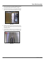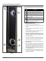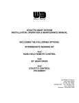
1
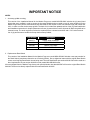
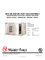
MSA-SB-2600 MILITARY SUB-ASSEMBLY HIGH EFFICIENCY ELECTRIC CONVECTION OVEN INSTALLATION - OPERATION - service - parts models MSA-SB-2600 MSA-SB-2692 NSN: 9Z 7310-01-519-8399 APL: 43A040025 MF P/N: 98-3600 (No Drain) NSN: TBD APL: TBD MF P/N: 98-3660 (Liner Drain) 44 Lakeside Avenue, Burlington, Vermont 05401 USA Telephone: (802) 658-6600 Fax: (802) 864-0183 www.mfii.com PN 14-0395 Rev a (9/14) © 2014 - Market Forge Industries Inc. TABLE OF CONTENTS IMPORTANT WARNING: Improper installation, adjustment, alternation, service or maintenance can cause property damage, injury or death. Read the installation, operation and maintenance instructions thoroughly before installing or servicing this equipment. FOR YOUR SAFETY Do not store or use gasoline or other flammable vapors or liquids in the vicinity of this or any other appliance. INSTALLATION Introduction.. . . . . . . . . . . . . . . . . . . . . . . . . . . . . . . . . . . . . . . . . . . . . . . . . . . . . . . . . . . . . . 2 Assembly Instructions. . . . . . . . . . . . . . . . . . . . . . . . . . . . . . . . . . . . . . . . . . . . . . . . . . . . . 3 Main Frame Assembly. . . . . . . . . . . . . . . . . . . . . . . . . . . . . . . . . . . . . . . . . . . . . . . . . . . . . 4 Oven Cavity Assembly.. . . . . . . . . . . . . . . . . . . . . . . . . . . . . . . . . . . . . . . . . . . . . . . . . . . . 6 Control Panel Assembly. . . . . . . . . . . . . . . . . . . . . . . . . . . . . . . . . . . . . . . . . . . . . . . . . . . 8 Inside Oven Cavity Assembly. . . . . . . . . . . . . . . . . . . . . . . . . . . . . . . . . . . . . . . . . . . . . 13 Door Assembly. . . . . . . . . . . . . . . . . . . . . . . . . . . . . . . . . . . . . . . . . . . . . . . . . . . . . . . . . . 15 Outer Skin Assembly. . . . . . . . . . . . . . . . . . . . . . . . . . . . . . . . . . . . . . . . . . . . . . . . . . . . . 16 OPERATION Control and Operating Instructions.. . . . . . . . . . . . . . . . . . . . . . . . . . . . . . . . . . . . . . . . 18 MAINTENANCE Cleaning. . . . . . . . . . . . . . . . . . . . . . . . . . . . . . . . . . . . . . . . . . . . . . . . . . . . . . . . . . . . . . . . 19 The information contained in this manual is important for the proper installation, use, and maintenance of this oven. Adherence to these procedures and instructions will result in satisfactory baking results and long, trouble free service. Please read this manual carefully and retain it for future reference. Troubleshooting.. . . . . . . . . . . . . . . . . . . . . . . . . . . . . . . . . . . . . . . . . . . . . . . . . . . . . . . . . 20 Wiring Diagram. . . . . . . . . . . . . . . . . . . . . . . . . . . . . . . . . . . . . . . . . . . . . . . . . . . . . . . . . . 21 illustrated parts list Recommended Spare Parts.. . . . . . . . . . . . . . . . . . . . . . . . . . . . . . . . . . . . . . . . . . . . . . 22 Door Assembly with Slide Latch. . . . . . . . . . . . . . . . . . . . . . . . . . . . . . . . . . . . . . . . . . . 23 Control Panel with Probe Option.. . . . . . . . . . . . . . . . . . . . . . . . . . . . . . . . . . . . . . . . . . 24 appendix Oven Performance. . . . . . . . . . . . . . . . . . . . . . . . . . . . . . . . . . . . . . . . . . . . . . . . . . . . . . . 26 ERRORS: Descriptive, typographic or pictorial errors are subject to correction. Specifications are subject to change without notice. Spec Information.. . . . . . . . . . . . . . . . . . . . . . . . . . . . . . . . . . . . . . . . . . . . . . . . . . . . . . . . 27 Spare Parts List Description.. . . . . . . . . . . . . . . . . . . . . . . . . . . . . . . . . . . . . . . . . . . . . . 28 Parts List Fasteners. . . . . . . . . . . . . . . . . . . . . . . . . . . . . . . . . . . . . . . . . . . . . . . . . . . . . . 29 IMPORTANT NOTICE NOTES 1. Accutemp griddle mounting; This version of the Installation Manual for the Market Forge oven model MSA-SB-2600 includes the (4) parts (listed below) that were modified in order to accept the Accutemp Griddle being mounted on top. All ovens shipped from the Market Forge factory with a Serial Number less than #226167 will require a back fit kit, Market Forge part number 984162, in order to mount the Accutemp griddle. The back fit kit includes the updated version of the (4) parts listed below and installation instructions. A simple replacement of these (4) parts with the back fit kit parts will allow the griddle to be mounted on top. The tools required to perform the replacement are a slotted screwdriver and a 7/16” socket wrench. List of (4) parts that were modified to accept the Accutemp Griddle; Part Number Description 98-3571 RIGHT SIDE CHANNEL 98-3572 LEFT SIDE CHANNEL 98-3586 FRONT TOP PANEL 98-3587 REAR TOP PANEL 2. Replacement Reed Switch This version of the Installation Manual for the Market Forge oven model MSA-SB-2600 includes a new part number for the Reed Switch (sometimes referred to as a Proximity Switch). Due to alignment issues with the original Reed Switch a new, more forgiving Reed Switch is now being used. The new Reed Switch part number 08-6615 should be used as a direct replacement for part number 08-6308 in older model MSA-SB-2600 ovens. All ovens shipped from the Market Forge factory with a Serial Number less than #225207 will have the original Reed Switch 08-6308. These can be directly replaced with the new Reed Switch 08-6615. Introduction YOUR ENERGY EFFICIENT CONVECTION OVEN HOW THE OVEN OPERATES MSA-SB-2600 convection ovens are electrically powered, high capacity ovens featuring high energy efficiency. These ovens are designed to radically cut power consumption, delivering the cooking power of a 16 KW oven from only 11 KW’s of energy input. Improvement of energy use is made possible by a carefully designed insulating system which keeps heat inside the oven longer. MSA-SB-2600 ovens operate by use of two simple controls, a power switch for turning on the fan motor and control circuit, and a thermostat for setting the oven temperature. The oven is otherwise automatic. A thermostat maintains oven temperature by cycling heating elements on and off, with temperature fluctuating no more than 20°F from the setting. Uniform distribution of heat within the oven is assured by continuous operation of a convector fan. A convector fan distributes heat uniformly throughout the oven interior, for fast even roasting and baking. A 60-minute and Constant Heat timer serves as an aid in using the oven, when the timer expires the heating elements shut off. To prevent unnecessary loss of heat when the doors are opened, an interlock switch stops fan operation whenever the right-side door is opened. Should the operator wish to cool the oven, opening just the left- side door will quickly ventilate the oven interior. Like all Market Forge products, MSA-SB-2600 ovens are built to the highest standards of workmanship, employing only the finest materials and components. Of course, Power Saver II ovens are fully approved by UL, and other official testing authorities. Installation 2 Assembly Instructions INTRODUCTION Time Estimate The model MSA-SB-2600: The estimated time for complete assembly is approx- mately 6-7 hours for a first timer or 4-5 hours for an experienced assembler. The oven assembly can be completed with one person, but for a more productive assembly two people are recommended. Submarine-Accessible Convection Oven contains 88 total parts for assembly and is designed such that it can be assembled in a submarine’s galley with simple tools. Sub-Assemblies Tools required for assembly: The total assembly is broken down into 7 sub-assemblies: • Main Frame Assembly • Oven Cavity Assembly • Control Panel Assembly • Motor/Transformer Assembly • Inside Oven Cavity Assembly • Door Assembly • Outer Skin Assembly • Power drill (Cordless drills 12 V or higher) • Screw driver set • Screw starter • Allen wrench set • Socket Set • Open wrench Set • Mallet Sealant Use RTV 106 high temperature silicone rubber adhesive sealant as needed to provide a tight seal to any area that requires it. Also use Loctite 268 on all fasteners that will be permanently fastened. 3 Installation Main Frame Assembly Figure 3 Item Description 1. Bolt together the split base front (1) to the split base rear (2) using seven ¼-20 hex bolts. Then fasten the Junction Box (11) to the split base rear using nuts. Part No. 1 Split Base Front 98-3569 2 Split Base Rear 98-3568 3 Rear U - Channel Frame 98-3574 4 Front Frame Weld Assembly 98-3622 5 Frame Liner Support/Back Channel 98-3563 6 Channel, Frame Top Left Side, Front to Back 98-3572 7 Channel, Frame Top Right Side, Front to Back 98-3571 8 Channel, Motor/Transformer Support 98-3590 9 Transformer Mounting Bracket 99-3291 10 Junction Box 98-3597 Figure 1 2. Bolt front frame weld assembly (4) to split base front/rear using three ¼-20 hex bolts at the base. Figure 2 Installation 4 Main Frame Assembly 3. Bolt Rear U-channel frame (3) to split base front/ rear assembly. There are welded bolts in the corner of the split base rear. Slip the rear u- channel over the bolts and use a two nuts to fasten it to the frame. 5. Bolt channel frame top (6), left side, and right side, front to back (7) to the Frame liner support/back channel and Rear U-channel frame. This will require six ¼-20 hex bolts, two for each member. NOTE: The backside needs only nuts since the bolts are welded to each part. Figure 4 Figure 6 4. Install the Frame liner support/back channel (5) with flanges facing to the rear of the oven and vent hole positioned on the left (Viewing from front of oven). This part will align over two welded slots but will NOT be fastened. 6. Bolt two motor/transformer supports (8) to Frame liner support/back channel using 5/16”-18, 3-inch bolts with spacers and two 5/16”-18 nuts per spacer. Flanges must face inward towards each other. See “Figure 6”. 7. Bolt on the transformer-mounting bracket (9) to the bottom of the right (viewing from back end of oven) motor/transformer support (No picture), using two hex head screw Figure 5 Figure 7 5 Installation Oven Cavity Assembly 1. Lay the split liner bottom (2) flat and place the Ushaped split iner gasket (3) around the split liner bottom. Figure 9 2. Bolt on loosely the split liner rear (4) to the split liner bottom using 1/4-20 hex bolts. Then put the vertical split liner gasket (7) hanging on the top bolt of the left and right side. Figure 8 Item Description Part No. 1 Split Liner Top 98-3576 2 Split Liner Bottom (Has 2 Crease Lines) 98-3655 3 U-Shaped Split Liner Gasket (2) 98-1796 4 Split Liner Rear 98-3579 5 Split Liner Left 98-3577 6 Split Liner Right (Has Slots in Corner for Heating Element) 98-3578 7 Vertical Split Liner Gasket (2) 98-1797 8 Cavity White Insulation (2) 15-7561 9 Insulation Straps with Clips (2) 10 Rear Cavity Insulation (Not Shown) 98-3613 11 Top Cavity Insulation 1.5” Thick (Not Shown) 98-3619 Figure 10 3. Bolt the split liner left (5) and split liner right (6) to the split liner bottom and split liner rear. NOTE: The split liner right has holes in it for the heating element. NOTE: 15 parts total Figure 11 Installation 6 Oven Cavity Assembly 4. Then place another U-shaped split liner gasket (3) around the top and finish by bolting the split liner top (1) to the rest of the cavity. Now fasten each and every bolt without moving the gaskets. Then apply silicon sealant to areas of need. As a reminder the front face flanges of the cavity must be flush. 6. Install the whole cavity to the mainframe and secure with four #8-32 S.S hex nuts to the weld studs on the corners of the cavity thru the front frame weld assembly. Figure 15 Figure 12 7. Wrap the cavity with two layers of oven cavity insulation (8) starting from the right side of the oven and use two wire straps to fasten them down. Once insulated cut away insulation for heating element to exit from oven cavity. NOTE: The corner hole does not have a bolt. Otherwise interference will occur. Figure 13 5. Install rear cavity insulation (10) mounting over spacer bolts protruding from the frame liner support/back channel. Figure 16 8. Then add the top cavity insulation (11) to the top of the cavity. It will not be strapped down. Figure 14 Figure 17 7 Installation Control Panel Assembly Figure 20 Item Description 1. Bolt on the Inner insulation panel mounting bracket (11) to the inner insulation/electric panel divider (3) and then fasten it to the Frame liner support/back channel using three self-taping screws.Then fasten the nuts on the inner insulation panel mounting bracket where it sleeves over the front frame weld assembly. Part No. 1 Front Control Panel 98-3592 2 Electric Control Panel 98-3627 3 Inner Insulation/Electric Panel Divider 98-3575 4 Conduit Raceway Tubing 98-3596 5 Conduit Coupling (2) 10-8935 6 Flexible Conduit 32” (2) 7 Flexible Conduit 12” 8 High Limit Thermostat Mounting Bracket 99-4688 9 Reed Switch Bracket 98-3560 10 High Limit Thermostat 08-6351 11 Inner Insulation Panel Mounting Bracket (Not Shown) 98-3558 Figure 18 NOTE: 13 parts total Figure 19 Installation 8 Control Panel Assembly 2. Attach the reed switch bracket (9), which is part of the control panel to the insulation/electric panel divider. NOTE: The position of the reed switch must be such that it is in the most forward position relative to the front of the oven. Figure 23 Figure 21 5. Install 2 conduit couplings (5) on the conduit raceway tubing (4) and install this combination to the electric control panel and junction box. 3. Bolt the green ground wire of the front control panel (1) to the frame as seen in the picture. Use a #10-32 keps nut to fasten to the stud located behind the front frame weld assembly. 6. Then install the flexible conduit tubing for the high limit thermostat (7), motor (6), and transformer (6). The high limit thermostat has two lead wires that are white and is positioned through the third hole down from the top of the frame liner support/back channel. Do the same for the motor which has three wires numbered 45, 46 and 52.Then again for the transformer, which has four wires numbered 36, 37, 38 and 39 where the transformer conduit is on the bottom of the three. Figure 22 4. Fasten the front control panel to the front frame weld assembly using four #8-32 pan head screws, one in each corner of the control panel face. Then attach the electric control panel (2) to the insulation/electric panel divider using three self-taping screws. Figure 24 NOTE: The tubing for the thermostat is 12” while the motor and transformer is 32”. 9 Installation Control Panel Assembly 7. Attach the high limit thermostat-mounting bracket (8) to the Frame liner support/back channel using two self-taping screws. 8. Connect the high limit thermostat (10) to the two lead wires and then fasten to the inside of the cavity using two #6-32 screws. Figure 25 Figure 26 Installation 10 Motor Transformer Assembly Figure 28 Item Description 1. Attach motor (2) to the motor mount bracket (1). Then install this combination from the inside of the cavity with the motor wires positioned on the top. Do not bolt to cavity at this point. Part No. 1 Motor Mount Bracket 99-3930 2 Motor 09-7248 3 Transformer 09-6475 4 Fan 98-3598 5 Motor Cover Plate Gasket 98-3566 6 Motor Mount Cover 99-3931 7 Standoff/Baffle with Screw (4) 98-3599 8 Thermostat Bracket Top 99-0950 9 Thermostat Bracket Bottom 99-0951 10 Support Brace Angle 98-3639 11 Motor Mount Insulation 10-0811 NOTE: There should be three spacer nuts between the motor and the motor mount bracket. NOTE: 14 Parts Total Figure 27 11 Installation Motor Transformer Assembly 2. Place the white motor mount insulation (11) over the motor mount bracket. Tuck the left and right sides of the insulation down into the space on both sides of the motor mount bracket. Then place the motor cover plate gasket (5) over the motor mount gasket (placement is important since the gasket is NOT square). Figure 31 5. Install the transformer (3) where the bottom will slot into the transformer-mounting bracket. Then fasten down the top of the transformer to the motor/transformer support channel using two ¼”-20 bolts. The transformer should be positioned as closely to the cavity as possible. Figure 29 3. Install the motor cover (6) over the gasket. Then place the thermostat bracket top (8) over the top right bolt and the thermostat bracket bottom (9) over the bottom right bolt. Fasten all four using hex nuts. Figure 32 6. Have an electrician wire the motor and the transformer following the wiring diagram as in drawing number 98-3542, which is shown in Appendix A, page 20 of this manual. Figure 30 7. Install the support brace angle (10) to the motor/ transformer support channels. Tighten in place. 4. Install the fan (4) over the motor shaft. Once positioned over the shaft use an allen wrench to fasten the fan to the shaft. Then install four stanoff/baffle’s (7) with screw to the four bolts of the motor mount. NOTE: Fan front surface and the end of the shaft face should be flush to each other as shown by the arrow. Figure 33 Installation 12 Inside Oven Cavity Assembly Figure 35 Item Description 1. Install the vent tube (3) using four self-taping screws. Then install the side rack clips (5), four on each side of the oven and use two self-taping screws per clip. Part No. 1 Heating Element (480 V) 98-1777 2 Baffle 98-1766 3 Vent Tub 98-3557 4 Element Support Bracket 98-3588 5 Side Rack Clip (8) 99-3097 6 Capillary Clip (2-3) 99-0953 7 Grommet 91-6491 8 Side Rack (2) 98-3621 9 Element Gasket 98-3561 NOTE: 18 Parts Total Figure 34 13 Installation Inside Oven Cavity Assembly 4. Place the element gasket (9) on the heating element (1) and install using four allen set screws. Bolt down the element using #8-32 keps nuts. 2. Install the element support bracket (4), which will be to the left of the fan, using two self-taping screws. Figure 36 Figure 38 3. Install the grommet (7) on the right side of the cavity. Then punch a hole through the grommet and CAREFULLY unwind the thermostat capillary tube located behind the front control panel and feed it through the grommet and into the cavity. 5. Connect the heating element to the proper cables as indicated in the wiring diagram located in Appendix A of this manual (6 wires). Run the capillary tube along the top of the cavity to the back and down through the thermostat brackets. Use capillary clips (6) to fasten the tube using selftaping screws. Figure 39 6. Attach the baffle (2) and side racks (8) to the inside of the oven cavity as shown. Use four ¼”-20 shoulder bolts for the baffle. Figure 37 Figure 40 Installation 14 Door Assembly 1. Install horizontal liner gasket (6) on top andbottom of the front frame weld assembly using #8-32 pan head screws. Door Handle Part No. 10-0657 2. Install left and right vertical door liner gaskets (5) using #8-32 pan head screws. 3. Install the two door top latch (3) in the top-middle of the front frame weld assembly using #8-32 countersunk screws. 4. Install left and right door (1-2). Fasten door bearing using #10-32 flat head countersunk screws and nuts. NOTE: Adjust doors as necessary to properly align them. may require a few adjustments. This is very important. Door lock latch (4) will not be installed at this time. Figure 42 Figure 41 Item Description Part No. 1 Left Door 98-3629 2 Right Door 98-3589 3 Door Top Latch (2) 99-5946 4 Door Lock Latch 98-3595 5 Left & Right Vertical Door Liner Gasket (2 pieces) 98-3611 6 Horizontal Door Liner Gasket (2) 98-3610 NOTE: 9 Parts Total Figure 43 15 Installation Outer Skin Assembly 1. Install the bottom u-channel cover (2) and the top Uchannel cover (3) to the front frame weld assembly. No screws or bolts needed. Just pop in the parts. Figure 45 2. Install door lock latch using #8-32 quarter pan head screws. NOTE: Close door and adjust as needed. Figure 46 3. Install two, corner channel cover’s (4) using two #8-32 pan head screws on the bottom only. Figure 44 Item Description Part No. 1 Side Frame Skin (2) 98-3624 2 Bottom U-Channel Cover 98-3585 3 Top U-Channel Cover 98-3643 4 Corner Channel Cover (2) 98-3581 5 Split Top Rear Cover 98-3587 6 Split Top Front Cover 98-3586 Figure 47 NOTE: 8 Parts Total Installation 16 Outer Skin Assembly 4. Have an electrician wire a power supply line through the raceway conduit rates at 480 VAC, 3 Phase. 5. Install the side frame skin (1) on the right and left side of the oven. Use one #8-32 pan head screw per side. Figure 48 6. Install the split top cover (5) and screw the rear corner to the corner channel using two #8-32 pan head screws per corner. 7. Lastly install the split top front (6) and fasten to the split rear using seven #8-32 quarter pan head screws. Figure 49 17 Installation Control and Operating Instructions The controls required to operate the oven are listed in the following table together with a short functional description of each. 1 2 Item Description 1 Thermostat Control - Regulates oven temperature. Controls heating element operation. 2 Thermostat Light - Indicates when the thermostat is calling for heat and the elements are ON. 3 Timer/Constant Heat - Electrical timer to aid in time cooking cycles. Controls oven and constant heat mode. 4 Power Light - Indicates power is ON. 5 Power/Fan Switch - Three position fan switch. Controls fan speed either HIGH/LOW or in the middle position the oven is OFF. Operating Instructions 1. Check that power is available to the oven 2. Arrange shelf positions according to the item to be cooked. 3. Close doors. Move fan switch to HIGH or LOW. Fan should come on. 4. Set thermostat dial to desired cooking temperature. Element indicator light should come on 5. Allow oven to preheat for about 5-10 minutes. Preheating is complete when indicator light goes out and the buzzer sounds. Do not waste energy by turning the oven on too early. 6. Load oven. The load should be adjacent to the oven, so the doors will be open as short a time as possible. 3 7. Close doors. Set timer for desired cooking time. 8. Buzzer will sound at end of preset interval. Oven is ready to unload. 5 9. If oven temperature is to be lowered, set the thermostat to the desired temperature to cool interior. Fan will continue to run with left door open and right door closed. Where indicator light comes on, oven is at lower temperature. Close left door. When light goes off, oven is ready for use. 4 10. For daily shutdown, place oven thermostat and power switch in OFF position. For extended shut- down, leave doors ajar as well. Figure 50 operation 18 Cleaning A good preventive maintenance program in the form of daily cleaning procedures is outlined in the following steps: 1. Remove oven shelves and wash in mild detergent and water. Rinse and dry. 2. Remove left and right hand shelf supports by lifting up and out toward center of oven. Wash, rinse and dry. 3. Remove fan baffle by lifting up and out. Wash, rinse and dry. 4. Wash interior sides, bottom, and top with mild detergent and water. A stainless steel cleaner (not polish) should be used for the interior. Rinse and dry. 5. Replace fan baffle, shelf supports and shelves. 6. Wash both sides of doors, top & bottom trim using a stainless steel cleaner. Rinse and dry. 19 maintenance Troubleshooting PROBLEM Probable Cause REMEDY CONVECTOR FAN FAILS TO OPERATE Power to oven is off. Locate external circuit breaker for power and place in ON position. Power switch off. Place in ON position. Right oven door open. Close Door. Control circuit breaker off. Place in ON position. Faulty circuit breaker, door interlock switch, fan motor, or Refer to wiring diagram or obtain outside service. wiring. INDICATOR LIGHT FAILS TO LIGHT WITH FAN OPERATING, THERMOSTAT SET Indicator light burned out. Replace light. See service and parts manual for procedure. Electrical failure. Refer to wiring diagram or obtain outside service. FAN OPERATION - NO HEAT Thermostat not set. Set thermostat. Faulty contactor, wiring, electrical failure. Refer to wiring diagram or obtain outside service. maintenance 20 Wiring Diagram Figure 51 21 maintenance Recommended Spare Parts Part No. Description Qty. 10-7371 SwitchPower/Fan 1 10-5052 Light, Fan Power 1 10-5052 Light, Heating Element 1 08-6615 Reed Switch 1 08-6472 Relay, 120V 1 08-6475 Relay, Socket 1 10-4714 Thermostat, 475oF 1 09-5259 Thermostat, Knob 1 08-6464 Timer 1 08-3826 Timer, Knob 1 10-5944 Contactor 1 09-7248 Motor, 2 Speed 1 08-6351 Hi-Limit, Thermostat 1 08-6468 Fuse, 5Amp 2 09-6475 Transformer, 500VA 1 10-7395 Buzzer, 120 Volt 1 08-7978 Fan, Cooling 1 98-1777 Element, Heating (480V) 1 08-6469 Fuse, Holder 2 Illustrated Parts list 22 Door Assembly with Slide Latch 1A 2 4 5 11 6 1A 12 13 Kit #98-3694 14 6 15 5 2 4 3 1 7 Note: Kit #98-3694, Parts Not Sold Separately. 3 10 8 9 1 1A Figure 52 Item Part No. Description 1A 98-3694* Kit, Door Bearing & Pin, Top & Bottom, MSA-SB-2600 1 98-3691 Bearing Lock, Bottom, No Notches 2 98-3552 Bearing Block, Top, with Notches on both sides 3 98-3689 Pin, Door, Bottom, without Dowel Pin 4 98-3551 Pin, Door, Top, with Dowel Pin 5 98-3693 Assy, Right Door Pin & Bearing, Top 6 98-3692 Assy, Left Door Pin & Bearing, Top 7 09-3427 Hex Head Bolt, 1/4-20 Thd 8 98-3607 Bracket, Slide/Safety Latch 9 08-7990 Screw, 1/4-20 Thd Truss Hd 1/2” Lg 10 08-7989 Spacer, Door Slide 11 99-5950 Embossed Door Latch 12 10-2146 Screw, #6-32 1/4” Lg, Pan Head 13 98-3546 Inner Door Assy 14 98-3608 Outer Door, Left Side without Slide 15 98-3609 Outer Door, Right Side with Slide * Kit #98-3694, Parts Not Sold Separately. 23 Illustrated Parts List Control Panel with Probe Option Figure 53 Item Part No. Description 1 08-7978 Fan, Cooling 2 08-6472 Relay, 120 Volts 3 08-6469 Fuse, Holder 4 08-6552 Terminal Strip 5 09-6575 Plug, Hole 6 10-5944 Contactor 7 98-1720 Terminal Block 8 08-6475 Relay, Socket 9 98-3562 Panel, Electric Controls 10 08-6468 Fuse, 5 Amps 11 10-1720 Screw, #6-32 Thread x 1/2” Long, Stainless Steel 12 08-7993 Screw, #6-32 Thread x 1 1/2” Long, Stainless Steel 13 10-1761 Screw, #8-32 Thread x 3/8” Long, Stainless Steel Illustrated Parts list 24 Control Panel with Probe Option Figure 54 Item Part No. Description 1 98-1717 Control Panel, Embossed 2 10-7395 Buzzer 3 10-5052 Light, Power & Fan 4 09-5259 Knob, Thermostat 5 10-4717 Thermostat 6 08-7979 Controller, Meat Probe 7 08-6597 Switch, Mode 8 08-3826 Knob, Timer 9 08-6464 Timer 10 10-7371 Switch, Power/Fan 11 98-3543 Lexan, Control Panel, without Probe 12 98-1775 Lexan, Control Panel, with Probe 25 Illustrated Parts List Oven Performance Verification Check List 5. Verify that the racks do not bind at 400°F. 1. Verify that the doors are properly aligned and that there is no interference occuring at room temperature and 400oF. 2. Verify that all screws and bolts are tight. Verify the accuracy of the oven’s thermostat at 350°F by comparing the temperature control setting to the temperature at the center of the oven (one thermocouple). The maximum difference is to be no more than +/- 5°F. 3. Verify that the blower fan can operate at high and low speeds. Sub-Oven, Convection Oven, No Probe. Wiring Diagram - 480 V, 3 Phase, 11 kW, 60 Hz A DRA WING NUMBER C 98-3542 RE V. 4. Clean oven with a rag and run oven for 2 hours to burn off oil, clean interior prior to use. Figure 55 appendix 26 Spec Information MODEL: MSA-SB-2600 OPTIONAL AT EXTRA COST: SIZE: 35-1/4” Deep x 36” Wide x 25-1/4” High (896mm Front-to-Back x 914mm Wide x 641mm Top-to-Bottom) • Extra shelves_______quantity. • Meat Probe/Thermometer. DESCRIPTION: Will be a Market Forged Military SubAccessible High Effiiency Electric Convection Oven equipped with COOK & CONSTANT COOK controls. CONSTANT COOK permits operator to preset oven to cook food at a constant temperature for a infinte amount of time. • 1 3/4” Diameter Liner Drain. • Legs (4) with Flanged Feet (3/4-10” Thread). EC EP Exterior will be finished with stainless steel panels, top, rear, sides .Oven liner will be wrapped with a minimum .75’’ (19mm) High-Grade insulation. French type doors will open a full 180° and will be: Stainless steel with a minimum of .75’’ (19mm) insulation. Electrical Connection - Connection for incoming power supply wires on terminal block. Power Supply - 1 3/8 (44mm) access holes for power supply wires. Use wire suitable for at least 90°C. Nominal amp per line wire per oven: 11kW. VOLTS Oven interior dimensions will be 27 3/8” wide x 20” high x 24 5/8” deep (695mm wide x 508mm high x 625mm deep). 480 (440-480) 1pH 3pH ---- 15 Details of other electrical systems available upon request. Oven interior will be stainless steel with coved corners and a water-proof design. Oven shelves and shelf supports will provide nine shelf positions centered 2” (51mm) apart. Shelf stops on oven shelf will prevent tipping within the shelf supports. Five shelves will be furnished as standard. Safety door latch designed to keep doors closed in any pitch and roll environment is included. Controls will be located on an embossed recessed panel on the right front of oven. Controls will include main power switch, thermostat with indicator light and temperature range of 200°-475°F (93°-246°C), mechanical 60-minute and Constant cook timer with audible alarms that sound at end of the preset interval. A 2-speed fan selector switch with HIGH or LOW modes. Controls will also include a high limit cut-off. Convector fan will turn on automatically when power is on and right door is closed. Fan will turn off automatically when right door is opened. For rapid cooling purposes, it will be possible to operate convector fan with left door open in order to quickly evacuate heated air from oven. Convector fan motor will be rated at 1/4 HP. Oven will be completely serviceable from the front. Back of oven will be completely enclosed and suitable for installation tight against a non-combustible wall. OPERATION WILL BE BY: Oven will be rated at 11 KW, and equipped for operation on: • 480 VAC, 3 pH Oven controls will operate on nominal 120 volts AC. Figure 56 27 appendix Spare Parts List Description Part No. Description Qty 10-7371 Switch, Power/Fan 1 10-5052 Light, Fan Power 1 10-5052 Light Heating Element 1 08-6615 Reed, Switch 1 08-6472 Relay, 120 Volt 1 10-4714 Thermostat, 475oF 1 09-5259 Thermostat, Knob 1 08-6464 Timer 1 08-3826 Timer, knob 1 10-5944 Contactor 1 09-7248 Motor, 2 Speed 1 08-6351 Hi-Limit, Thermostat 1 08-6468 Fuse, 5 Amp 2 09-6475 Transformer, 500 VA 1 10-7395 Buzzer, 120 Volt 1 08-7978 Fan, Cooling 1 98-1777 Element, Heating 1 08-8004 Loctite 268 1 08-8003 RTV 106 Silicone Sealant 1 08-7999 * Hardware Kit (Fasteners) 1 98-3623 Complete Spare Parts Kit 1 * NOTE: For individual fasteners refer below for specific part numbers. appendix 28 Parts List Fasteners Length (inches) Thread Size Qty SCREW CAP HEX HEAD 0.5 1/4”-20 77 10-1814 SCREW CAP HEX HEAD 0.75 1/4”-20 7 08-7840 NUT, SERRATED FLANGE 1/4”-20 73 08-7995 BOLT, HEX HEAD 5/16”-18 4 08-7956 NUT, SERRATED FLANGE 5/16”-18 8 10-2045 SCREW CAP HEX HEAD 0.5 #10-32 2 08-7996 TEK SCREW PHILLIPS PAN HEAD #2 0.5 #10-16 10 10-2146 SCREW, SLOTTED PAN HEAD 0.25 #6-32 26 10-1728 SCREW, PHILLIPS FLAT HEAD C-SUNK #8-32 8 08-7994 SCREW, PHILLIPS FLAT HEAD C-SUNK 1 #10-32 8 10-1749 SCREW, MACHINE ROUND HEAD 0.25 #8-32 6 10-1761 SCREW, MACHINE TRUSS HEAD #8-32 41 10-2571 NUT, KEPS #8-32 20 08-8005 NUT, SERRATED FLANGE #10-32 8 08-7992 SOCKET SET SCREW #8-32 4 10-1790 SCREW, CAP HEX HEAD 1/4”-20 8 10-1939 BOLT, SHOULDER 0.5 1/4”-20 4 08-7991 SCREW, SLOTTED FLAT HEAD C-SUNK 0.5 #8-32 2 08-7990 SCRW, SLOTTED TRUSS HEAD 0.5 1/4”-20 3 08-3822 WASHER, STAINLESS STEEL TYPE B 1/4” 4 Part No. Description 10-1864 3 1 29 appendix