1
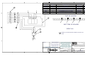
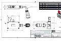
STILETTO MAST SYSTEM
INSTALLATION, OPERATION & MAINTENANCE MANUAL
INCLUDING THE FOLLOWING OPTIONS:
INTERMEDIATE SENSING KIT
And
HAND-HELD REMOTE CONTROL
And
90° GEAR DRIVE
And
STILETTO CONTROL
P/N 4086801
The Will-Burt Company
169 S. Main Street
Orrville, OH 44667
330-682-7015 – Fax: 330-684-1190
www.willburt.com
Revision 7, November, 2008
`
Stiletto
WARRANTY
The Manufacturer warrants its products to be free from defects in material and workmanship for a
period of one year from the date of shipment from the factory. The Manufacturer shall not be
responsible for any damage resulting to or caused by its products by reason of improper
installation, improper storage, unauthorized service, alteration of products, neglect or abuse, or
use of the product in a manner inconsistent with its design, accident, acts of God, or failure to
properly maintain this product. This warranty does not extend to any component parts not
manufactured by Manufacturer, however, Manufacturer's warranty herein shall not limit any
warranties made by manufacturers of component parts which may extend to Buyer.
THE FOREGOING WARRANTY IS IN LIEU OF ALL OTHER WARRANTIES, AND NO
REPRESENTATIONS, GUARANTEES OR WARRANTIES, EXPRESS OR IMPLIED,
(INCLUDING, BUT NOT LIMITED, TO A WARRANTY OF MERCHANTABILITY OR FITNESS
FOR A PARTICULAR PURPOSE) ARE MADE BY MANUFACTURER IN CONNECTION WITH
THE MANUFACTURE OR SALE OF ITS PRODUCTS. NO EMPLOYEE, DISTRIBUTOR, OR
REPRESENTATIVE IS AUTHORIZED TO CHANGE THIS WARRANTY IN ANY WAY OR
GRANT ANY OTHER WARRANTY ON BEHALF OF MANUFACTURER.
Claims for defects in material and workmanship shall be made in writing to Manufacturer within
thirty (30) days of the discovery of defect. Failure to provide notice as required hereby shall be
conclusive evidence that the product was in conformity with the warranty, and the Manufacturer
shall be released from any and all liability relating to the product. Manufacturer may either send a
service representative or have the product returned to its factory at Buyer's expense for
inspection. If judged by Manufacturer to be defective in material or workmanship, the product will
be replaced or repaired at the option of Manufacturer, free from all charges except authorized
transportation.
THE REMEDIES OF BUYER SET FORTH HEREIN ARE EXCLUSIVE AND ARE IN LIEU OF
ALL OTHER REMEDIES. THE LIABILITY OF MANUFACTURER WHETHER IN CONTRACT,
TORT, UNDER ANY WARRANTY, OR OTHERWISE, SHALL NOT EXTEND BEYOND ITS
OBLIGATION TO REPAIR OR REPLACE, AT ITS OPTION, ANY PRODUCT OR PART FOUND
BY MANUFACTURER TO BE DEFECTIVE IN MATERIAL OR WORKMANSHIP.
MANUFACTURER SHALL NOT BE LIABLE FOR COST OF INSTALLATION AND/OR
REMOVAL, OR BE RESPONSIBLE FOR DIRECT, INDIRECT, SPECIAL OR CONSEQUENTIAL
DAMAGES OF ANY NATURE.
Page ii
`
Stiletto
TABLE OF CONTENTS
1. CHAPTER 1
1
1.1 Safety Precautions ................................................................................................................................... 1
1.2 Introduction .............................................................................................................................................. 1
1.3 Description ............................................................................................................................................... 1
1.4 Reference Data ........................................................................................................................................ 3
2. CHAPTER 2
3
2.1 Introduction .............................................................................................................................................. 4
2.2 Installation ................................................................................................................................................ 4
3. CHAPTER 3
5
3.1 Introduction .............................................................................................................................................. 5
3.2 Discussion on the Control ........................................................................................................................ 6
3.3 Powered Operation .................................................................................................................................. 8
3.4 Manual Operation…………………………………………………………………………………………………9
3.5 Error Messages ...................................................................................................................................... 10
3.6 Operator Maintenance ........................................................................................................................... 10
4. CHAPTER 4
11
4.1 General .................................................................................................................................................. 11
4.2 Maintenance Instructions ....................................................................................................................... 13
4.3 Troubleshooting………………………………………………………………………………………………….16
4.4 Instructions for Clearing Heavy Ice Buildup……………………………………………………………...……19
5. CHAPTER 5
21
5.1 Introduction………………………………………………………………………………………………………21
5.2 Reference Drawings .............................................................................................................................. 21
LIST OF ILLUSTRATIONS
Figure 4-1-1 Lubrication Point on Mast Drive
Figure 4-1-2 Lubrication Point on 90 Degree Manual Crank Input Gear Box
Figure 4-1-3 Manual Crank Input Gear Box Assembly
Figure 4-2 Lubricating the ACME Screw
Figure 4-3 Ice Removal Areas
Figure 4-4 Lock Housing Ice Removal Area
Figure 5-1 40868 Control Box Sheet 1
Figure 5-2 40868 Control Box Sheet 3
Figure 5-3 B-54878 Stiletto Base Hole Locations
Figure 5-4 B-3766 Hand Held Remote Control
Page iii
14
14
15
16
20
21
`
Stiletto
LIST OF TABLES
Table 1-1 Reference Data
Table 3-1 Error Messages
Table 4-1 Preventive Maintenance Schedule
Table 4-2 Expendable and Durable Items Required
3
10
12
13
SAFETY SUMMARY
The following are general safety precautions that are not related to any specific procedures and therefore do not appear
elsewhere in this publication. These are recommended precautions that personnel must understand and apply during
many phases of operation and maintenance.
SHOCK HAZARD
Observe general safety precautions for handling equipment using high voltage. Always disconnect power before
performing repair or test operations.
HEALTH AND SAFETY HAZARD
Solvent used to clean parts is potentially dangerous. Avoid inhalation of fumes and also prolonged contact to skin.
RESUSCITATION
Personnel working with or near high voltages should be familiar with modern methods of resuscitation. Such information
may be obtained from the Bureau of Medicine and Surgery, United States Navy.
Page iv
`
Stiletto
A WARNING is used to call your attention to a potentially hazardous
situation, which, if not avoided could result in death or serious injury.
A CAUTION is used to call your attention to a potentially hazardous
situation, which, if not avoided, may result in minor to moderate injury
and/or property damage.
The following warnings appear in the text and are repeated here for emphasis.
Do not operate the mast system until you have made certain that the
area of operation is free of overhead power lines and other unwanted
sources of electricity.
Death or serious injury could occur if alcohol is not handled carefully.
Use it in a well-ventilated area away from open flame, arcing equipment,
ignition sources, heaters or excessive heat. Always store alcohol in a
properly marked container. Do not smoke.
Do not move the mast while it is being raised. This applies especially to
vehicle mounted masts.
Do not move the mast once it has been extended. This applies
especially to vehicle mounted masts.
Make sure there is adequate clearance above the mast system before
applying power and operating the system.
Page v
`
Stiletto
At all times prior to system operation you should insure that:
•
The mast extension path is free of personnel and mechanical
obstruction.
•
All electrical cables are undamaged and properly terminated.
•
The control is receiving proper voltage and current.
•
The payload is properly installed.
•
Any transit tie-downs on the payload have been removed.
•
The mast base is not moving.
•
The area above the mast is free of mechanical obstructions. Striking
an overhead obstruction can damage the mast and leave it partially
extended. It can also damage the payload.
•
Ensure the area above the mast is free of electrical wires. Operator
death may occur by extending the mast into power lines.
•
Coaxial and payload control cables are not tangled and that they are
free to pay out as the mast is extended.
Deviation from standard operating conditions could cause mast failure.
Use care when manually extending or retracting the mast tubes because
the normal stops and protections are being bypassed.
Voltage may be present which can cause severe electrical shock. Always
ensure that all electrical circuits to the mast are de-energized and
properly tagged during manual operation.
Page vi
`
Stiletto
This Stiletto Mast System is supplied with a friction slip clutch to prevent
serious damage to the mast in the event of a jam. There is no way to
detect the action of the slip clutch other than operator observation.
When the clutch begins to slip, that is, when the motor is running and the
mast is neither extending nor retracting, release the extend/retract toggle
switch immediately to avoid overheating the clutch.
Always turn off power before servicing the mast system.
Make sure all personnel stay clear of the mast and the direction of travel
in which it is pointed.
Only trained and qualified personnel should install, use and service this
equipment.
Before performing maintenance or repair, make sure that the Stiletto
Mast System is level and secure. Injury to personnel or damage to
equipment could occur if the Stiletto Mast System tips over.
Any attempt to electrically energize the Stiletto Mast System when
manually operating the mast may result in injury. Always ensure that all
electrical circuits to the mast are de-energized and properly tagged to
prevent injury during manual operations.
An external 15 Amp Time Delay fuse (FNM-15) must be installed must
be installed between the control box and the customers power supply.
Excessive current can damage the control box. Reversed polarity power
leads will damage the control box.
Page vii
`
Stiletto
INTRODUCTION
SAFETY PRECAUTIONS
Refer to the Safety Summary for precautions to be observed while operating or servicing this equipment.
INTRODUCTION
This manual covers the operation, maintenance, troubleshooting and installation instructions for the Stiletto Mast System.
The Stiletto Mast System consists of a control system, telescoping mast, 28 VDC drive unit, support bracket assembly,
assorted cables, hardware, an intermediate height readout option, a handheld remote control option and a 90° gear drive
option.
DESCRIPTION
1.3.1 Control System
The control system combines customer input, power input, sensor input and power output to allow the customer to
raise and lower the mast without running past sensor limits. It also keeps track of cycles to aid in preventative
maintenance, and has some self-diagnosing capability. It is housed in a NEMA 4X box. The control system also
includes fully extended and nested sensors that mount on the mast. It includes an eight digit, IR secure, green LED
display which displays status, error codes and intermediate heights.
1.3.2 Telescoping Mast
The telescoping mast provides the structure that supports the payload. It consists of (9) concentric carbon epoxy
composite tubes. Each tube has two internal keys that match with keyways on the adjacent tube to establish azimuth
integrity.
1.3.3 28 VDC Drive Unit
The Screw Drive Stiletto Mast has an ACME screw located in the center of the telescoping mast. As the screw
rotates it sequentially lifts up the mast sections. Each moving mast section (all but the base tube) has an ACME nut
attached to its bottom. The drive unit extends and retracts the telescoping mast in response to either input from the
control system, or by manually cranking the drive. Under powered operation the motor is dynamically braked for a
short period of time at the end of each motion. The system has sufficient internal friction to keep the mast extended at
any desired height when not powered.
1.3.4 Support Bracket Assembly
The support bracket assembly attaches to the telescoping mast and to the customer’s vehicle or structure. Along with
the mounting holes in the base of the drive it is an essential part of the mounting of the Stiletto Mast System.
1.3.5 Assorted Cables
Two cables, one for power and one for signals, are permanently attached to the 28 VDC Drive Unit. They have a
length of 3 meters, and have MS screw type connectors to attach to the bottom of the control system box.
Page 1
`
Stiletto
1.3.6 Hardware
Hardware includes nuts and bolts for the support bracket assembly, a grease gun and a manual crank handle.
1.3.7 Intermediate Height Readout
The intermediate height readout utilizes a proximity sensor that reads the drive sprocket and converts the reading into
an extension height of the mast. The readout (in either feet or meters) is incorporated into the control system display.
When the mast is fully extended the control box display will read, “ DEPLOYED,” and when the mast is nested the
control box will read, “NESTED.”
1.3.8 90° Gear Drive Variant
The Will-Burt Company offers variants of its standard models with a 90° gear drive installed on the manual crank
point. This allows the user to access the manual crank point from the side or the rear rather than from above. The 90°
gear drive should only be used for manual extension and retraction in the event of an electrical power loss. Damage
to the 90° gear drive could result from trying to input too much torque by hand, such as breaking through ice, or other
similar high torque applications.
1.3.9 Hand Held Remote Control Option
This option consists of a small NEMA 4X box containing a switch that will raise and lower the mast. It includes an
extension cable with a MS screw connector that screws into the bottom of the control box. In addition to the control
switch there are three indicator lights that indicate the status of the Stiletto Mast System; nested, partially deployed
and deployed.
1.3.10 PC Interface
A Personal Computer Interface is an option for controlling the mast height. Standard functions include controls for
raising, lowering, stowing and stopping the mast. Additional operational functions include the ability to move the mast
to a desired height and to monitor the various mast parameters and limit switch inputs in real time.
Page 2
`
Stiletto
REFERENCE DATA
Reference data for the Stiletto Mast System is given in Table 1-1.
Table 1-1 Reference Data
Functional Characteristic
4 Meter
6 Meter
10 Meter
15 Meter
Mast System Weight (mast
control box, cables, bracket)
190 lbs
203 lbs.
246 lbs.
300 lbs
Fully Nested Height
39”, +1, -0
46”, +1, -0
67”, +1, -0
94.5”, +1, -0
Fully Extended Height
165”, +2, -0
228”, +2, -0
394”, +2, -0
590.5”, +4, -0
Maximum Payload
200 lbs.
200 lbs.
175 lbs.
125 lbs.
Extension Time (28 VDC)
<90 sec.
<120 sec.
<200 sec.
<330 sec.
Extension Time (18.1 VDC)
<135 sec.
<180 sec.
<300 sec.
<500 sec.
Operating Voltage Range
18.1-33 VDC
18.1-33 VDC
18.1-33 VDC
18.1-33 VDC
Max Tilt from Vertical
10°
10°
10°
5°
Operational Wind Speed
Consult Factory
Consult Factory
Consult Factory
Consult Factory
Survival Wind Speed
Consult Factory
Consult Factory
Consult Factory
Consult Factory
*Current Draw, 125 lb Payload
at 28 V
10A
10A
10A
10A
Inrush Current
120A
120A
120A
120A
Typical Ice Breaking Operating
Current
30A-40A
30A-40A
30A-40A
30A-40A
* For proper operation under full load conditions, power supply must maintain 18.1 Volts at control, at up to 60 Amps for 2
second intervals and 40 Amps continuous. If voltage drops below 5 Volts at any time, damage to the control may occur.
Page 3
`
Stiletto
CHAPTER 2-INSTALLATION
2.1 INTRODUCTION
This section provides instructions for installing the Stiletto Mast System.
2.2 INSTALLATION
2.2.1 Mast
2.2.1.1 Refer to the top level assembly drawing supplied with your mast. Match holes for the base of the mast and for
the support bracket, and create mounting places in the host site. The mast should be as plumb as possible.
Make sure the installation site does not interfere with the cables.
2.2.1.2 Note that there are (14) drain holes (3/8” diameter, quantity 13; 7/16” diameter, quantity 1) on the bottom of
the mast to drain off rain water and condensation. Refer to drawing B-54878, Stiletto Drain Hole Locations, in
your reference drawings. The surface to which the base of the mast bolts must allow for drainage.
2.2.1.3 Bolt the mast into place. Mount the support bracket using customer supplied 3/8 inch diameter or M10
stainless steel fasteners with a stainless steel flat washer and means to prevent loosening. Secure the base of
the mast with customer supplied ½ inch diameter or M12 stainless steel fasteners with a heavy duty extra thick
(MS 15795-819) stainless steel flat washer and means to prevent loosening.
2.2.2 Controls
2.2.2.1 Refer to Drawing 40868 located in Section 5.2, Reference Drawings, for the hole pattern of the control. Use
either ¼ inch diameter or M6 stainless steel fasteners and means to prevent loosening.
2.2.2.2 Refer to Drawing 40868, sheet 1 and 3, located in Section 5, Reference Drawings for the location of the
connector for the user supplied power. This mast system is designed to operate on 28 VDC power per MIL-STD
1275. The mast system does NOT have a master power switch. If such a switch is desired the integrator must
provide it with the supplied power. An external 15 Amp Time Delay (FNM-15) fuse must be installed by the
customer.
2.2.3 Power Cable Requirements
2.2.3.1 The unit requires a customer supplied 12 gauge power cable. With long cable runs, a heavier gauge wire may
be needed. Power is applied through a supplied MS3106E20-16S connector or equivalent.
2.2.3.2 The control has three handshaking features detailed in section 3.2.1.5. They are:
1. A precondition contact closure,
2. A fully nested enable circuit,
3. A full extended enable circuit.
These circuits use the power connector 000013-409-001 to connect with the world. Of immediate concern is the
precondition contact closure. For the mast to operate this closure must be made either with a purposeful switch
OR WITH A JUMPER. See Sheet 3 of Drawing 40868, Stiletto Control Box. Any jumper must be part of the
cable because the control box is sealed for warranty purposes.
Page 4
`
Stiletto
CHAPTER 3- OPERATING THE MAST
3.1 INTRODUCTION
This chapter of the Stiletto Mast System manual will cover the following topics:
a. A description of the control with reference to its workings and capabilities.
b. A discussion of the Human-Machine interface with the controls, describing the up/down switch and the display.
c.
A discussion of the optional Intermediate Height Readout and the optional Hand Held Remote Control.
d. Instructions in the normal (powered) operation of the mast system.
e. Instructions in manual operation of the mast system using the hand crank. Included is a discussion of the 90° Gear
Drive variant.
f.
A review of the ERROR MESSAGES of Table 3-1 available in the control.
Page 5
`
Stiletto
3.2 DISCUSSION ON THE CONTROL
At all times prior to system operation you should insure that:
•
The mast extension path is free of personnel and
mechanical obstruction.
•
All electrical cables are undamaged and properly
terminated.
•
The control is receiving proper voltage and current.
•
The payload is properly installed.
•
Any transit tie-downs on the payload have been
removed.
•
The mast is not moving.
•
The area above the mast is free of mechanical
obstructions. Striking an overhead obstruction can
damage the mast and leave it partially extended. It can
also damage the payload.
•
Ensure the area above the mast is free of electrical
wires. Operator death may occur by extending the mast
into power lines.
•
Coaxial and payload control cables are not tangled and
that they are free to pay out as the mast is extended.
3.2.1 Description of Controls
3.2.1.1 Enclosure - The controls are contained in an aluminum NEMA 4X box. Please refer to
drawings 40868 in the reference section for its size and for the location of the mounting holes. The box
contains the screw bulkhead connectors for the signal and power cables from the mast, for the cable for
the optional hand held remote, and for the customer-supplied power and handshake signals. It also
contains an up/down switch and an 8-character alphanumeric display.
Deviation from standard operating conditions could cause
mast failure.
3.2.1.2 MOSFETS – The control box uses MOSFETS for electrical switching purposes. The main
function of the control is to manage motor direction and to dynamically brake the motor for a short
period of time at the end of each motion. The motor draws about 10 Amperes continuously and about
120 Amperes on start-up under “normal” conditions (See Table 1-1). However, to ensure proper
operation under high load and/or icing conditions, a minimum 18.1 Volt supply voltage must be
maintained at the control at up to 60 Amps for 2 second intervals and 40 Amps continuous.
Page 6
`
Stiletto
Damage to the controls may occur if voltage drops below 5
Volts during operation of the mast.
3.2.1.3 Sensors - The control relies upon two limit sensors attached to the mast. The fully nested
sensor is a mechanical limit switch, which is triggered when a probe attached to the bottom of the
center tube hits the lever on the switch. The full extension sensor is a reed switch attached to the
outside of the base tube which detects the approach of a permanent magnet attached to the bottom of
the largest moving tube. A proximity sensor is used to determine the height readout of the mast
sections during deployment and retraction. The mast height is displayed on the control box.
3.2.1.4 Capabilities - The control allows for the powered extension and retraction of the Stiletto Mast
System. It uses the input from two extreme limit switches to prevent the user from over-extending or
over-nesting the mast. When a directional command is terminated, the control automatically shorts the
motor leads to dynamically brake the motor for a short period of time. The control is wired for an
optional handheld remote control. The alphanumeric display shows status of the mast (nested,
intermediate height readout and fully deployed), the number of cycles on the mast and any error
messages.
3.2.1.5 Handshaking - The control (see drawing 40868) has three handshake signals. The first is an
input for a hatch switch or other pre-condition contact closure. An open circuit will cause the control to
display its software revision and will inhibit extension. This input must be driven by an isolated contact
closure capable of handling 20 milliamperes at 28 volts. The second signal is for a remote enable
output. This is an isolated relay contact that closes when the mast is fully nested. This could be used
to prevent an external operation unless the mast is fully nested. The third signal is an isolated relay
contact that closes when the mast is fully extended. These contacts are rated for 1 Ampere at 28 VDC.
3.2.1.6 Intermediate Height Readout - This mast is supplied with intermediate height readout. It
consists of a proximity sensor that reads the drive sprocket and converts the reading into an extension
height of the mast. The readout in the control display window is zeroed out at the nested height. If the
mast is never nested, because of a saddle type mounting system, then the displayed height will
compound in error the more times the mast is extended. In metric mode the display reads “XX.XX M”
where XX.XX is the extension of the mast in meters. The resolution is .01 meters and the accuracy is ±
.02 meters. In English mode the display reads “XX.XX F” where XX.XX is the extension of the mast in
feet. The resolution is .01 feet and the accuracy is ± .05 feet. As the mast extends, the display shows
the extension rather than enunciating “PARTIAL”. Remember, extended height equals extension PLUS
the nested height.
3.2.2 Human-Machine Interface
3.2.2.1 On the side of the main control box is an SPDT (Mom-Off-Mom) toggle switch that is used by
the operator for raising or lowering the mast. The switch is protected by a switch guard and a
waterproof boot.
3.2.2.2 On front of the control box is an eight character green LED alphanumeric display. This shows
the status of the mast, either NESTED, intermediate height, or fully DEPLOYED. With the intermediate
height readout gives the extension of the mast in at a height above the nested height. It can also give
the number of cycles on the mast, and a variety of error messages.
Page 7
`
Stiletto
At all times prior to system operation insure that:
•
The mast area is free of personnel and mechanical
obstruction.
•
All electrical cables are undamaged and properly
terminated.
•
A power source capable of delivering specified system
voltage and current has been properly connected to the
Control Enclosure.
3.2.3 Options
3.2.3.1 Hand Held Remote - This mast may be supplied with a hand held remote control (See Drawing
B-3766). It consists of a small NEMA 4X box that contains an SPDT (Mom-Off-Mom) toggle switch that
is used by the operator for raising or lowering the mast. This switch is protected by a switch guard and
a waterproof boot. It also has three red LED indicators that light appropriately when the mast is fully
nested, partially extended or fully deployed. They backlight appropriate text to enunciate these
messages. The hand held remote does NOT have an alphanumeric readout displaying extended
height. The hand held remote control attaches via an extension cable to a bulkhead connector on the
bottom of the control box.
3.3 POWERED OPERATION
3.3.1 Turn System On
The mast control does not have a master power switch. The operator powers up the system at the level
of the vehicle or shelter by supplying power to the proper contacts on the control box connector. If
desired, the integrator can provide a master power switch upstream from the mast system. The control
will generate a sign-on message of “STILETTO” at power up for a short period of time, and finally will
display NESTED, intermediate height, DEPLOYED or some error code as appropriate.
3.3.2 Raise the Mast (Standard)
Place the Mast UP / DOWN switch in the UP position. As long as the switch is held in the UP position the
mast will raise. If the switch is engaged long enough, the mast will automatically stop when the full
extension limit switch is made. At that point the alphanumeric display will say DEPLOYED. If the UP /
DOWN switch is released before the maximum extension the mast will quickly stop, and the alphanumeric
display will say display the intermediate height.
3.3.3 Lower the Mast (Standard)
Place the Mast UP / DOWN switch in the DOWN position. As long as the switch is held in the DOWN
position the mast will continue to lower. If the switch is engaged long enough the mast will automatically
stop when the full nested limit switch is made. At that point the alphanumeric display will say NESTED. If
the UP / DOWN switch is released before nesting the mast will quickly stop, and the alphanumeric display
will display the intermediate height.
3.3.4 Access the Number of Cycles
When the mast is nested releasing the toggle switch and then reapplying the toggle switch in the DOWN
direction will cause the control to display the number of cycles on the mast.
Page 8
`
Stiletto
3.4 MANUAL OPERATION
3.4.1 Normal Operations
This mast may be raised or lowered manually. Refer to your top level assembly drawing to find the
square end shaft on the drive unit that is the manual input point. Use the hand crank provided to raise
(clockwise) or to lower (counter-clockwise) the mast. When the mast is not powered the motor leads are
not shorted together thus disabling dynamic braking. The normal limit switches are not in effect during
manual operation. There are mechanical hard stops just beyond both the upper and lower limit switch
locations that will stop the mast safely. Nevertheless, it is good practice to stop the mast at the normal
positions.
3.4.2 The 90° Gear Drive Option
The manual input point can normally only be accessed from above. The Will-Burt Company offers a 90
degree gear box variant which bolts onto the manual input point and provides an identical ½ inch square
interface to the hand crank. This variant can be oriented either to the side or to the rear per customer
instruction. The operation is identical to 3.4.1. The 90° gear drive should only be used for manual
extension and retraction in the event of an electrical power loss. Damage to the 90° gear drive could
result from trying to input too much torque by hand, such as breaking through ice, or other similar high
torque applications.
Page 9
`
Stiletto
3.5 ERROR MESSAGES
There are two error messages. Error messages and their meaning are shown in Table 3-1.
Table 3-1 Error Messages
Code
“CONFLICT”
“L.S. ERR”
Meaning
Conflicting requests between the local UP / DOWN and the remote UP / DOWN switches
have occurred. The mast will come to a stop, and normal operation will resume when at
least one of the switches is returned to the “OFF” position.
Both the Upper and Lower limit switches are open, indicating the impossible state of being
fully extended and fully nested at the same time. The fault can only be cleared by turning off
the control and correcting the problem. This will most often mean that there is a broken wire
connection, one of the limit switches is defective, or the sensor cable is disconnected.
3.6 OPERATOR MAINTENANCE
Specific to the control system, only nominal routine maintenance is required. Refer to the mast operations
manual for detailed mechanical maintenance requirements. On a routine basis—WEEKLY—perform the
following:
a. Insure that all mounting fasteners are tight, particularly on the motor.
b. Insure that all cable connections are snug.
c.
Inspect all cables for frayed and damaged wiring.
d. Using a soft, non-abrasive cloth, wipe the bezel clean on the alphanumeric display.
e. Refrain from applying a stream or high pressure water directly to the control box.
Page 10
`
Stiletto
CHAPTER 4- MAINTENANCE AND SERVICE INSTRUCTIONS
4.1 GENERAL
Preventive Maintenance Checks and Services (PMCS) means systematic care, inspection and servicing of
equipment to keep the system in good condition and to prevent breakdowns. When received for maintenance, the
assembly has been removed from the site on which it was mounted and is otherwise fully assembled. Removal
typically requires disconnecting the power and signal cables from the mast control box, removal of the mast
payload, removal of the mast support bracket assembly and removal of the mounting screws from the base plate.
Consult vehicle manual for specific installation details. All procedures must be performed by trained personnel
only. The Will-Burt Company recommends that the owner create and maintain a maintenance log for each mast.
4.1.1 Schedule.
4.1.1.1 The Preventative Maintenance Schedule provided in Table 4-1 lists inspections and care required to
keep the Stiletto Mast System in good operating condition.
4.1.1.2 The Interval column specifies when to do a certain check or service.
4.1.1.3 The Procedure column specifies how to do the required checks or services or refers to a specific
procedure. Follow these instructions carefully.
4.1.1.4 The Not Fully Mission Capable If: column lists when the Stiletto Mast System is non-mission
capable and why it cannot be used.
4.1.1.5 If the Stiletto Mast System does not perform as required, see section 4.3 Troubleshooting.
4.1.1.6 If anything looks wrong and cannot be diagnosed and/or fixed, the Mast System should be taken to
the next higher level maintenance facility or returned to the Will-Burt Company for disposition.
4.1.1.7 Record all inspection and maintenance activities in the mast system’s maintenance record log.
When doing PMCS, several soft, clean rags will always be required. The following are common procedures
and checks:
a. Keep it clean. Dirt, grease, oil and debris only get in the way and may cover up a serious
problem. Clean as you work and as needed. Use denatured alcohol on all metal surfaces. Use
water when cleaning rubber or plastic material. Use soap and water when cleaning the mast
tube’s exterior surfaces.
b. Rust and Corrosion. Check for rust and corrosion. If any bare metal or corrosion exists, remove
it with a wire brush and repair with touchup paint.
c.
Bolts, Nuts and Screws. Check for obvious looseness, missing, bent or broken condition. It is
not practical to check all hardware installation torques, but look for chipped paint, bare metal or
rust around bolt heads. If you find a bolt, nut or screw that is loose, tighten it.
d. Electric Wires and Connectors. Look for cracked, frayed or broken insulation, bare wires and
loose or broken connectors. Replace as required. Tighten loose connectors.
Page 11
`
Stiletto
Table 4-1 Preventive Maintenance Schedule
Item
No.
1
Interval
During
operation
Location/Item to
Check
Base of Mast
Tube
Assemblies
2
Weekly
Mast Exterior
Surfaces
3
Weekly
Mast Exterior
Coating
4
Weekly
Mast Exterior
Fasteners
5
Weekly
Mast Exterior
Operation
6
Weekly
Cycle Counter
7
Weekly
Cables and
Bulkhead
Connectors
8
Weekly
Mast Top
Mounting
Adapter
9
Weekly
Mast Exterior
Surfaces
10
250
Cycles
500
Cycles
2500
Cycles
Lube port on
side of mast
Base of Mast
Drive Unit
Replacement of
Nuts
10,000
Cycles
Mast
11
12
13
Page 12
Procedure
During extension and retraction of the mast
and antenna, observe the outer surface of the
tubes for damage and accumulation of
foreign material.
Visually check for foreign material, damage
or obstructions. Remove any foreign material
or obstructions as necessary.
Check condition of coating. Coating shall be
in good condition with no bare metal or
composite material exposed.
Visually check that all fasteners are tight. Pay
special attention to those attaching the
Stiletto Mast System to the site, the mast to
the drive unit, the motor to the drive unit, and
the payload to the mast.
During extension and retraction of the mast,
observe the mast operation for evidence of
binding.
Check that counter is operating properly by
noting that during initial cycle of the mast the
counter increases by one. Refer to
paragraph 3.3.6 for cycle counter operation.
Check that connectors are clean, pins are
undamaged, and threads are in good
condition. Check for looseness and damage
to insulation.
Check that plate is firmly attached to top tube
assembly, threaded holes are in good
condition, and no damage has penetrated
anodization. Replace damaged adapter plate
or tighten to composite top tube as required.
Check all visible surfaces of the mast for
damage, especially cracking. Pay particular
attention to the base of the mast.
See paragraph 4.2.2 “Lubricating the ACME
Screw”
See paragraph 4.2.1 “External Lubrication”
Special Training Requirements. Contact WillBurt Co. for details about factory training
and/or factory rebuild.
Return for complete factory overall and
rebuild.
Not Fully Mission
Capable if:
Tubes are damaged
Loose fasteners
joining major
components cannot be
tightened.
Binding is observed.
Connector is damaged
too severely to mate
with corresponding
cables.
Plate is loose or
threaded inserts are
missing or damaged.
Cracks are visible in
mast composite
material.
Mast will not work.
Mast will not work.
Mast will not work.
N. A.
`
Stiletto
4.1.2 Expendable and Durable Items Required. Table 4-2 lists the expendable and durable items required to
perform preventive maintenance on the Stiletto Mast System.
Table 4-2 Expendable and Durable Items Required
Item No.
Item Name, Description, Part Number
U/M
1
Alcohol, denatured
OZ
2
Lubricant, Drive Screw, Will-Burt P/N 912542
OZ
3
Oil, engine, SAE 30 (preferred) or 15W40
QT
4
Rags, wiping, clean
EA
4.2 MAINTENANCE INSTRUCTIONS
4.2.1.1
External Lubrication
Refer to Table 4-1 and perform the following procedure every 500 cycles.
a. Remove protective cap over manual drive shaft. (See Figure 4-1-1)
b. Using an oil can or eye dropper, apply 3 to 5 drops of SAE 30 (preferred) or 15W40 engine oil (Item 3,
Table 4.2) to bushing supporting the manual drive shaft.
c. Wipe off excess oil. Replace protective cap.
4.2.1.2 External Lubrication – 90 degree Manual Crank Input Gear Box (if Applicable-Optional)
Refer to Table 4-1 and perform the following procedure every 500 cycles.
a. Remove the four #8-32 X ¾ SHCS, SSTL bolts attaching the 90 degree gear box to the upper tension
slider. (see Figure 4-1-2 and 4-1-3)
b. Remove the 90 degree gear box from the upper tension slider. (see Figure 4-1-3)
c. Use a clean screw driver or punch to pack drive screw lubricant part number 912542 into the driven
hollow shaft. Fill the cavity between the driven hollow shaft and the bearing plug with lubricant
completely. (see Figure 4-1-3)
d. Wipe off excess lubricant before assembly, and ensure that the hollow shaft keyway is not packed with
lubricant to allow clearance for the 90 degree gear box shaft to fit.
e. Replace the 90 degree gear box onto the upper tension slider, and check for alignment of the bolt holes.
Also, check that the gear motor keyway is aligned in the driven hollow shaft. (see Figure 4-1-3)
f.
Apply Loctite 242 and tighten the four #8-32 X ¾ bolts.
Page 13
`
Stiletto
Figure 4-1-1 Lubrication Point on Mast Drive
Figure 4-1-2 Lubrication Point on Mast Drive-90 degree Manual Crank Input Gear Box (if Applicable)
Page 14
`
Stiletto
Figure 4-1-3, Manual Crank Input Gear Box Assembly
4.2.2 Lubricating the ACME Screw. Refer to Figure 4.2 and perform the following procedure every 250 cycles.
a. Charge the Grease Gun Assembly (Item No. 912541), supplied with each mast, with a cartridge of Drive
Screw Lubricant, Will-Burt part number 912542, ordered separately.
Do not substitute any grease for the Will-Burt Drive Screw
Lubricant, 912542. This is a super-premium aerospace grade
product, and is required for specified performance and life.
Before performing maintenance or repair, make sure that the
Stiletto Mast System is level and secure. Injury to personnel or
damage to equipment could occur if the Stiletto Mast System tips
over.
b. Extend the mast completely.
c.
Remove the hex shaped plug from the grease port about 16 inches up on the side of the mast base tube.
See Figure 4-2.
d. Remove the hydraulic coupling (cap) from the output tube of the grease gun assembly. Insert the tube
through the access hole and apply a generous dab of grease onto the screw. Jog the mast about ½ inch
(one half revolution of the screw) and apply another generous dab.
e. Replace the access plug into the access plate. Screw the hydraulic coupling (cap) back onto the output
tube of the grease gun.
f.
Retract the mast completely, extend it completely and retract it completely to distribute the grease over
all the nuts and the complete screw.
g. Record the date, cycle count and procedure in the mast’s maintenance record.
Page 15
`
Stiletto
Figure 4-2 Lubricating the ACME Screw
4.3 TROUBLESHOOTING
The following pages show many of the more probable error conditions. Where more than one probable cause can
explain an error condition, they are listed in an “indented” fashion, with specific corrective actions for each situation
further indented. Causes are listed in order of probability from highest to lowest. It should be noted that some
“errors” are more aptly called “states”, and do not necessarily indicate improper operation.
4.3.1 Pre-Condition Contact Closure Condition
Provisions have been made (see paragraph 3.2.1.4) for a pre-condition contact “handshake” circuit. If the
circuit is open the operation of the mast is prevented and the software revision level is displayed on the
alphanumeric display. This feature is normally disabled by a jumper installed across the connector pins. The
typical application of this capability is a sensor on a hatch above the mast. Correcting the condition will clear
this error.
a. Pre-condition is not present (i.e. the hatch is closed).
Corrective Action: Establish the proper pre-condition (i.e. open the hatch).
b. Damaged/inoperative pre-condition switch.
Corrective Action: Check the switch for continuity and replace if necessary.
c.
Missing connector wire (no handshaking used). (There is no hatch.)
Corrective Action: Refer to drawing 40868, and replace a jumper between the two appropriate contacts.
d. Malfunctioning mast control panel.
Corrective Action: Contact authorized service center for evaluation and possible return for repair.
4.3.2 The Mast Has Stopped Moving Upward or Is Moving Very Slowly.
Page 16
`
Stiletto
This Stiletto Mast System is supplied with a friction slip clutch to
prevent serious damage to the mast in the event of a jam. There
is no way to detect the action of the slip clutch other than operator
observation. When the clutch begins to slip, that is, when the
motor is running and the mast is neither extending nor retracting,
release the UP / DOWN toggle switch immediately to avoid
overheating the clutch.
a.
Interference to mast.
Corrective Action: Inspect and remove obstructions, tangled payload cables or lighten the payload.
b.
Damaged motor cable.
Corrective Action: Disconnect the motor cable from the mast. Inspect the cable for continuity and shorts.
Replace faulty cable.
c.
Damaged/inoperative motor.
Corrective Action: Replace the motor.
d. Malfunctioning mast control panel.
Corrective Action: Contact authorized service center for evaluation and possible return for repair.
e. ACME nuts fail to synchronize with ACME drive screw.
Corrective Action: Try retracting the mast three inches and approach that region again. If this does not
work the nuts may be worn out and will need to be replaced.
Corrective Action: Try raising the mast with the hand crank. There may be a burr on the nut, and action
with the hand crank, which is not limited by the torque limits on the friction safety clutch set at the factory,
may power through it. If this does not work the nuts may be worn out and will need to be replaced.
f.
Clutch is out of adjustment.
Corrective Action: The clutch may be in need of tightening. Contact authorized service center for
evaluation and possible return for repair.
4.3.3 The Mast Has Stopped Moving Downward.
This Stiletto Mast System is supplied with a friction slip clutch to
prevent serious damage to the mast in the event of a jam.
Detection of the clutch slipping is when the tube section does not
extend/retract when electrical power is applied via the UP/DOWN
toggle switch. Release the switch to avoid overheating the clutch.
a. Damaged motor cable.
Corrective Action: Disconnect the motor cable from the mast. Inspect the cable for continuity and shorts.
Replace faulty cable.
b. Damaged/inoperative motor.
Corrective Action: Replace the motor.
c.
Malfunctioning mast control panel.
Corrective Action: Contact authorized service center for evaluation and possible return for repair.
Page 17
`
Stiletto
d. ACME nuts fail to synchronize with ACME drive screw.
Corrective Action: Try raising the mast three inches and approach that region again. If this does not
work the nuts may be worn out and will need to be replaced.
Corrective Action: Try lowering the mast with the hand crank. There may be a burr on the nut, and
action with the hand crank, which is not limited by the torque limits on the friction safety clutch set at the
factory, may power through it. If this does not work the nuts may be worn out and will need to be
replaced.
e. Clutch out of adjustment.
Corrective Action: The clutch may be in need of tightening. Contact authorized service center for
evaluation and possible return for repair.
4.3.4 Nothing Works and the Display does not illuminate.
a. Power to the mast is interrupted at the shelter or vehicle level.
Corrective Action: Refer to shelter or vehicle level maintenance procedures.
b. Fuse Blown
Corrective Action: Replace external 15 Amp Fuse (Slow Blow FNM-15)
c.
The control box has been damaged.
Corrective Action: Contact Authorized Service facility for repair disposition.
4.3.5 Mast prematurely stops upward travel and control box indicates “DEPLOYED.”
a. A heavy object struck the mast during deployment causing the “DEPLOYED” limit switch to falsely
activate.
Corrective Action: Look over mast for damage and secure any loose objects.
Corrective Action: Lower the mast using the toggle switch for 3 (three) seconds until the Control Box
display no longer reads “DEPLOYED”. Use the toggle switch again, for 3 (three) seconds, to raise the
mast to full deployment height.
4.3.6 Control Box display reads “NESTED” when mast is partially extended.
a. Misinterpreted Electronic Limit Switch Status
Corrective Action: Motor needs to be operated continuously for 3 (three) seconds, for display to change
from “NESTED” to intermediate height status.
4.3.7 After Power cycle (switching main power off, then back on), the display does not read correct
“NESTED/ACTUAL INTERMEDIATE HEIGHT/DEPLOYED” status.
a. Must fully nest mast to re-zero height readout
b. Misinterpreted Electronic Limit Switch Status
Corrective Action: Motor needs to be operated continuously for 3 (three) seconds, for display to change
from “NESTED” to “PARTIAL” status.
4.3.8 Mast does not move up/down when switch is activated and control box display goes blank or restarts.
a. Insufficient voltage at control under load
Page 18
`
Stiletto
Corrective Action: Check supply voltage and power cabling.
4.4 SPECIAL INSTRUCTIONS FOR CLEARING HEAVY ICE BUILDUP
During periods of heavy precipitation and high ice buildup on the mast there is a chance of jamming during
retraction of a deployed mast. This high ice buildup on the collar sections (horizontal surfaces) of the mast could
cause the tube locks mechanisms to become “out of time” and cause internal damage. This ice buildup must be
cleared away during retraction just before the individual tube and collars contact each other. Shown on Page 20 are
the areas to clear the ice away from the tubes and collars prior to nesting. For instruction on how to remove ice
from a jammed lock assembly refer to Step 5.
The order of operations concerning the ice removal is as follows:
Note: Only retract the mast with electrical power, do not attempt to use the manual crank input. Internal damage
may occur using the manual crank during high torque applications.
Step 1. Attempt to retract the mast with electrical power only. If the mast begins to break the ice on its own,
proceed to Step 4. If the mast stalls and does not retract then proceed to Step 2. Do not continue to labor the
motor with a stalled tube set; because this will cause wear on the slip-clutch.
Step 2. Begin clearing away the ice on horizontal surfaces (collar) closest to the operator. Utilizing non-piercing
tools, begin by breaking the ice bond and using a striking motion away from the tube (tangent to the tube). Continue
to do this ice clearing around the collar. Then remove the remaining ice from the vertical lock post on the collar.
Next, begin to remove the ice buildup on the “nesting” tube. Use extreme caution when removing ice from the
circumference of the tube, only 1-2 vertical inches of ice will need to be removed. Use a tangential clearing motion
to keep from piercing the tube. Proceed to Step 3.
Step 3. Attempt to retract the mast electrically again. If the tube set is still stalled and will not retract, then ice has
built up internally and the unit will need to be thawed in order to regain functionality. Do not continue to labor the
motor with a stalled tube set; save the slip-clutch. If the mast does retract, proceed to Step 4.
Step 4. Continue to retract the tube until it is a few inches from nesting and contacting the lower collar. Begin
clearing away the ice on horizontal surfaces (collar) closest to the operator. Utilizing non-piercing tools, begin by
breaking the ice bond and using a striking motion away from the tube (tangent to the tube). Continue to do this ice
clearing around the collar. Next, remove the remaining ice from the vertical lock post on the collar. Then operate
the mast until the collars contact and the next tube begins to retract. At this point repeat Step 1 and 4.
Step 5. If the mast will continue to break ice during retraction but experiences trouble only near a locking transition,
then ice has frozen inside the lock body. This ice in the lock body is interfering with the normal unlocking of the
interfaces. To clear the ice, use a small, hard tool to reach inside the opening at the bottom of the housing.
Manually chip and clear the ice from the internal parts, then set the latch to the proper “Locked” orientation, as
illustrated on Page 21. Attempt to retract the mast again under electrical power.
Page 19
`
Stiletto
Utilizing non-piercing tools, remove the ice buildup from the indicated areas:
Figure 4-3, Ice Removal Areas
Page 20
`
Stiletto
Figure 4-4, Lock Housing Ice Removal
Once the internal ice is cleared away, observe the orientation of the lock mechanism. If it is witnessed to be in the
“Un-locked” position then push on the rocker to trip it back to the “Locked” position. When the mast operator has
clear access to the internal parts of the lock housing, the orientation should only be “Locked.” Under no
circumstance should the locks be simultaneously set in the “Un-locked” orientation, while the mast is being
operated.
CHAPTER 5- REFERENCE DRAWINGS
5.1 INTRODUCTION
This section provides reference drawings and photographs for use with the Stiletto Mast System.
(40868 pages 1 & 3, B-54878, B-3766, appropriate assembly drawing, and pictures as specified.)
Page 21
4
3
2
1
(11.97) in
(1.45) in
(10.22) in
ECN
REV
9213
C
9260
9318
D
E
REVISION HISTORY
DESCRIPTION
MAKE CHANGES FOR PHASE-IN OF PROX SENSOR & PC
INTERFACE; ADD ITEM #26 & #27
ADD: DESCRIPTIONS TO DIP SWITCH 4-5
ADD: INLINE FUSE KIT, J TERM'L I WAS J, ETC...
DATE
APPROVED
4/22/2008
DAJ/JDN
8/27/2008
11/7/2008
KV/
PCD/
NOTES:
1
(2.53) in
B
(6.30) in
(7.23) in
(2.46) in
(.18) in
10
9
5
TO MAST JUNCTION BOX, (LIMIT SWITCH, ETC).
(MS3102E16S-1S)
3
TO MAST DRIVE MOTOR.
(MS3102E16-11S)
4
TO HANDHELD REMOTE CONTROL OR PC
INTERFACE(OPTIONAL). (MS3102E20-7S)
MATING CONNECTOR REQUIRED:
000013-108-002 (MS3106E20-7P)
5
ALL KEYWAYS ARE ON TOP AS INDICATED BY
ARROWS.
6
MAST OPERATION TOGGLE SWITCH.
7
(.25) MOUNTING SCREW LOCATION TYP. 4
PLACES.
8
TO CUSTOMER POWER AND I/O
(MS3102E20-16P). MATING CONNECTOR
REQUIRED: 000013-108-004 (MS3106E20-16S)
9
DUST COVER, ( ITEM # 17 ) SHOULD BE
PLACED OVER RECEPTACLE 8-PIN E20-7S,
( ITEM # 6 ) WHEN NOT IN USE.
10
FOR DISPLAY TO BE RIGHT READING,
CONNECTORS MUST BE ALONG BOTTOM OF
ENCLOSURE AT CUSTOMER INSTALLATION.
11
TAMPER LABELS ARE PLACED OVER SEAM
OF BOX & LID AS SHOWN AFTER FINAL
INSPECTATION AND TESTING.
8
2
3
4
7
11
6
11
E
A
E
B
2
(3.54) in
1
ENTRANCE FOR CUSTOMER POWER 28v-DC
NOMINAL FUSED AT 15 AMPS 12 GA. WIRE
MINIMUM RECOMMENDED.
A
(4.33) in
UNLESS OTHERWISE SPECIFIED PROPRIETARY AND CONFIDENTIAL
DIMENSIONS ARE IN INCHES. THE INFORMATION CONTAINED IN THIS
TOLERANCES ON DECIMALS
0 = ` 0.060
ANGLES DRAWING IS THE SOLE PROPERTY OF THE
` 1/2~
00 = ` 0.030
000 = ` 0.005
(9.45) in
(.96) in
(9.85) in
4
K:\Inventor WorkGroups\WS-Vandegrift\Inventor\Mechanical Mast\Stiletto Control\40868.idw
APPROX. WT:
LB
THIRD ANGLE PROJECTION
3
FRACTIONAL ` 1/64"
1. ALL INSIDE EDGES TO HAVE
.005" TO .035" FILLETS.
2. ALL OUTSIDE EDGES TO HAVE
.005" TO .015" CHAMFER OR RADIUS.
125 ON ALL MACHINED SURFACES
WILL-BURT
WILL-BURT COMPANY ANY REPRODUCTION TITLE
IN PART OR WHOLE WITHOUT THE WRITTEN
PERMISSION OF THE WILL-BURT COMPANY IS
PROHIBITED.
APPROVALS
DRAWN
RCC
CHECKED
2
DATE
SIZE
10/11/2006
B
AN EMPLOYEE OWNED COMPANY
ORRVILLE, OH
STILETTO CONTROL
ASSEMBLY, MOSFET
DWG NO
40868
PN: 4086801
SHEET
1
REV
E
1
OF 3
4
3
2
1
ECN
REV
9213
C
9260
9318
D
E
REVISION HISTORY
DESCRIPTION
MAKE CHANGES FOR PHASE-IN OF PROX SENSOR & PC
INTERFACE; ADD ITEM #26 & #27
ADD: DESCRIPTIONS TO DIP SWITCH 4-5
ADD: INLINE FUSE KIT, J TERM'L I WAS J, ETC...
DATE
APPROVED
4/22/2008
DAJ/JDN
8/27/2008
11/7/2008
KV/
PCD/
NOTES:
ALL WIRE IS 20 GA UNLESS
OTHERWISE NOTED.
B
E
16 INPUT FOR HATCH SWITCH OR
OTHER PRE-CONDITION CONTACT
CLOSURE. OPEN CIRCUIT WILL
CAUSE CONTROL TO DISPLAY
IT'S SOFTWARE REVISION AND
INHIBITS EXTENSION.
E
17 CONTACTS INDICATING WHETHER
MAST IS FULLY NESTED OR NOT.
E
18 THE DIP SWITCH FUNCTIONS
ARE CONFIGURED AS FOLLOW:
18
20
SW1-1 Closed:
Open:
SW1-2 Closed:
Open:
SW1-3 Closed:
Open:
SW1-4 Closed:
Open:
SW1-5 Closed:
Open:
SW1-6 Closed:
Open:
E
16
19
1
17
E
B
Extension feedback enabled
No feedback
Feedback in feet
Feedback in meters
String pot feedback
Gear tooth pulse feedback
400 inch string pot
600 inch string pot
HD MosFet board present
Stand alone operation
Factory use only (debugging mode)
Normal system operation
19 PC INTERFACE (RS-485):
J4-A=DATA +
J4-G=DATA -
WILL-BURT FUSE KIT
E 20 INSTALLP/N
4022604
A
A
UNLESS OTHERWISE SPECIFIED PROPRIETARY AND CONFIDENTIAL
DIMENSIONS ARE IN INCHES. THE INFORMATION CONTAINED IN THIS
TOLERANCES ON DECIMALS
0 = ` 0.060
ANGLES DRAWING IS THE SOLE PROPERTY OF THE
` 1/2~
00 = ` 0.030
000 = ` 0.005
APPROX. WT:
LB
THIRD ANGLE PROJECTION
4
K:\Inventor WorkGroups\WS-Vandegrift\Inventor\Mechanical Mast\Stiletto Control\40868.idw
3
FRACTIONAL ` 1/64"
1. ALL INSIDE EDGES TO HAVE
.005" TO .035" FILLETS.
2. ALL OUTSIDE EDGES TO HAVE
.005" TO .015" CHAMFER OR RADIUS.
125 ON ALL MACHINED SURFACES
WILL-BURT
WILL-BURT COMPANY ANY REPRODUCTION TITLE
IN PART OR WHOLE WITHOUT THE WRITTEN
PERMISSION OF THE WILL-BURT COMPANY IS
PROHIBITED.
APPROVALS
DRAWN
RCC
CHECKED
2
DATE
SIZE
10/11/2006
B
PN:
AN EMPLOYEE OWNED COMPANY
ORRVILLE, OH
STILETTO CONTROL
ASSEMBLY, MOSFET
DWG NO
40868
SHEET
4086801
1
REV
E
3
OF 3
4
3
15
(x 2)
1
3
1
6
17
LID
4
16
2
ECN REV
6344-P
A
6992-P
B
7006-P
C
7034-P
D
7101-P
E
8856
F
8936
G
1
BASE
(x 4)
2
2
12
B
1
REVISION HISTORY
DESCRIPTION
DATE
SEE ECN
8/11/2003
ADDED 000048-029-902
10/11/2004
CHANGE COLOR OF PAINT -912202 10/18/2004
ADDED VIEW "A" TO SHEET 2
11/4/2004
CHANGED SCREW AND STANOFF 12/16/2004
(4) TERMINAL ETC & (1) LABEL
8/30/2007
ADDED 4214201, 50 FOOT CABLE
10/23/07
BY
MSmith
MSmith
JCM
MSmith
MSmith
pdietzel
PCD
APPR.
B
SCALE 3 / 4
3
8
7
5
SEAL 11
(x 2)
1
ATTACH TO LID USING
SILVER FILL EPOXY (P/N 35578)
9
10
13
SCALE 0.44 : 1
A
811138
LENGTH
20 FT
20 FT
50 FT
A
G
B
ASSEMBLY
P/N
912202
912254
4214201
C
PRIMER
811272
810759
811272
ASSEMBLY P/N TABLE
D
E
PRIMER
PAINT
CATALYST
811274
811273
810784
810798
811274
811273
F
PAINT
CATALYST
107756
810799
107756
G
1
2
3
PLACE ALL HARDWARE, THAT IS SUPPLIED
WITH 912454 ENCLOSURE, WITH ITEMS
KITTED FOR ASSEMBLY
1
2
3
4
5
6
SCALE 0.30 : 1
7
8
9
G
10
11
12
G
H
13
REDUCER COLOR
14
15
104064
BLACK
16
810785
WHITE
104064
BLACK
17
FIND
FINISH
MASK OFF INSIDE OF LID BEFORE PAINTING SO
THAT THE EPOXY (#35578) WILL HOLD THE
SECURE FILTER (#35540) .
SEE SHEET #3 FOR PROPER ORIENTATION.
ONLY OUTSIDE
NEEDS PAINTED
PER FINSH TABLE
912454
000016-011-001
912458
000016-011-004
35540
SCREW
3321
3319
912025
811138
SEAL
000051-000-012
000013-108-002
000045-990-001
3458
34706
4201101
PART NO.
UNLESS OTHERWISE
SPECIFIED DIM ARE IN
B-55140
HHRC ENCL. -STILETTO
SWITCH GUARD
B-6294
STILETTO HHRC BOARD
SWITCH TOGGLE SPDT MOM-OFF-MOM
EMI-RFI-1R SECURE FILTER
SCREW SUPPLIED WITH 912454
MS M4 X 12 PHIL PAN HD SSTL
SEALING RING 3/8" CONDUIT
STRAIGHT LIQUIDTITE CONNECTOR
CABLE
SEAL SUPPLIED WITH 912454
BOOT, SWITCH TOGGLE EMI/RFI
CABLE CONNECTOR
15/32 SEAL BUSHING FOR C&K
1/4" ALUM SPACER FOR #8 SCREW
TERMINAL ETC #AA-821-06-T
42011
REMOTE CONTROL LABEL
DRAWING
DESCRIPTION
BOM
THIS DOCUMENT CONTAINS
AND SHALL NOT BE USED OR
2 PL `.01 3 PL `.005
REPRODUCED OR ITS
INTERPRET DIM AND TOL PER
CONTENTS DISCLOSED IN
ASME Y14.5M - 1994
WHOLE OR IN PART, WITHOUT
THIRD ANGLE PROJECTION
TITLE
STILETTO HAND HELD REMOTE CONTROL
THE PRIOR WRITTEN CONSENT
OF THE WILL-BURT COMPANY
SIZE
DRAWN
APPROVED
3
A
INCHES. TOL ON ANGLE `.XX~ PROPRIETARY INFORMATION
msmith
4
1
1
1
1
1
4
2
1
1
SEE TABLE
1
1
1
1
2
4
1
QTY
2
6/16/2003
B
SCALE
DWG NO
SEE TABLE
REV
B-3766
SHEET
1
G
1
OF 3
4
3
2
1
REVISION HISTORY
ECN
6344-P
6992-P
7006-P
7034-P
7101-P
8856
8936
REV
A
B
C
D
E
F
G
DESCRIPTION
SEE ECN
ADDED 000048-029-902
CHANGE COLOR OF PAINT -912202
ADDED VIEW "A" TO SHEET 2
CHANGED SCREW AND STANOFF
(4) TERMINAL ETC & (1) LABEL
ADDED 4214201 ,50 FOOT CABLE
DATE
8/11/2003
10/11/2004
10/18/2004
11/4/2004
12/16/2004
8/30/2007
10/23/07
BY
MSmith
MSmith
JCM
MSmith
MSmith
pdietzel
PCD
APPR.
-
B
B
TOP OF BOARD
BOTTOM OF BOARD
VIEW A-A
16
3
WIRES TO ENTER BOARD FROM THE BOTTOM
SIDE.
A
A
FINISH
UNLESS OTHERWISE
SPECIFIED DIM ARE IN
THIS DOCUMENT CONTAINS
INCHES. TOL ON ANGLE `.XX~ PROPRIETARY INFORMATION
AND SHALL NOT BE USED OR
2 PL `.01 3 PL `.005
REPRODUCED OR ITS
INTERPRET DIM AND TOL PER
CONTENTS DISCLOSED IN
ASME Y14.5M - 1994
WHOLE OR IN PART, WITHOUT
THIRD ANGLE PROJECTION
SIZE
msmith
APPROVED
3
STILETTO HAND HELD REMOTE CONTROL
THE PRIOR WRITTEN CONSENT
OF THE WILL-BURT COMPANY
DRAWN
4
TITLE
2
6/16/2003
B
SCALE
DWG NO
SEE TABLE
REV
B-3766
SHEET
1
G
2
OF 3
4
3
2
1
REVISION HISTORY
1.34 in
[34 mm]
(
CABLE, SEE TABLE
)
ECN
6344-P
6992-P
7006-P
7034-P
7101-P
8856
8936
REV
A
B
C
D
E
F
G
DESCRIPTION
SEE ECN
ADDED 000048-029-902
CHANGE COLOR OF PAINT -912202
ADDED VIEW "A" TO SHEET 2
CHANGED SCREW AND STANOFF
(4) TERMINAL ETC & (1) LABEL
ADDED 4214201 ,50 FOOT CABLE
DATE
8/11/2003
10/11/2004
10/18/2004
11/4/2004
12/16/2004
8/30/2007
10/23/07
BY
MSmith
MSmith
JCM
MSmith
MSmith
pdietzel
PCD
APPR.
-
B
B
in
(3.86
[98 mm])
in
(4.28
[108.7 mm])
in
(2.52
[64 mm])
NESTED
PARTIAL
EXTENDED
3
SCALE 1 / 2
A
A
4.89 in
[124.2 mm]
(
)
FINISH
ONLY OUTSIDE
NEEDS PAINTED
PER FINSH TABLE
UNLESS OTHERWISE
SPECIFIED DIM ARE IN
THIS DOCUMENT CONTAINS
INCHES. TOL ON ANGLE `.XX~ PROPRIETARY INFORMATION
AND SHALL NOT BE USED OR
2 PL `.01 3 PL `.005
REPRODUCED OR ITS
INTERPRET DIM AND TOL PER
CONTENTS DISCLOSED IN
ASME Y14.5M - 1994
WHOLE OR IN PART, WITHOUT
THIRD ANGLE PROJECTION
SIZE
msmith
APPROVED
3
STILETTO HAND HELD REMOTE CONTROL
THE PRIOR WRITTEN CONSENT
OF THE WILL-BURT COMPANY
DRAWN
4
TITLE
2
6/16/2003
B
SCALE
.75
DWG NO
SEE TABLE
REV
B-3766
SHEET
1
G
3
OF 3