1
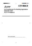
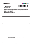
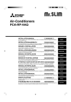
Air-Conditioners PCA-RP·HAQ INSTALLATION MANUAL FOR INSTALLER For safe and correct use, read this manual and the outdoor unit installation manual thoroughly before installing the air-conditioner unit. INSTALLATIONSHANDBUCH FÜR INSTALLATEURE Aus Sicherheitsgründen und zur richtigen Anwendung vor Installation der Klimaanlage die vorliegende Bedienungsanleitung und das Installationshandbuch gründlich durchlesen. MANUEL D’INSTALLATION Español PER L’INSTALLATORE Per un uso sicuro e corretto, prima di installare il condizionatore d’aria leggere attentamente il presente manuale ed il manuale d’installazione dell’unità esterna. E°XEIPI¢IO O¢H°IøN E°KATA™TA™H™ Nederlands PARA EL INSTALADOR Para un uso seguro y correcto, lea detalladamente este manual de instalación antes de montar la unidad de aire acondicionado. MANUALE DI INSTALLAZIONE Français VOOR DE INSTALLATEUR Lees deze handleiding en de installatiehandleiding van het buitenapparaat zorgvuldig door voordat u met het installeren van de airconditioner begint. MANUAL DE INSTALACIÓN Deutsch POUR L’INSTALLATEUR Avant d’installer le climatiseur, lire attentivement ce manuel, ainsi que le manuel d’installation de l’appareil extérieur pour une utilisation sûre et correct. INSTALLATIEHANDLEIDING English Italiano °π∞ ∞À∆√¡ ¶√À ∫∞¡∂π ∆∏¡ ∂°∫∞∆∞™∆∞™∏ °È· ÛˆÛÙ‹ Î·È ·ÛÊ·Ï‹ ¯Ú‹ÛË, ‰È·‚¿ÛÙ ÚÔÛÂÎÙÈο ·˘Ùfi ÙÔ ÂÁ¯ÂÈÚ›‰ÈÔ, ηıÒ˜ Î·È ÙÔ ÂÁ¯ÂÈÚ›‰ÈÔ ÂÁηٿÛÙ·Û˘ Ù˘ Â͈ÙÂÚÈ΋˜ ÌÔÓ¿‰·˜, ÚÈÓ ·fi ÙËÓ ÂÁηٿÛÙ·ÛË Ù˘ ÌÔÓ¿‰·˜ ÎÏÈÌ·ÙÈÛÙÈÎÔ‡. ∂ÏÏËÓÈο MANUAL DE INSTALAÇÃO PARA O INSTALADOR Para uma utilização segura e correcta, leia atentamente este manual e o manual de instalação da unidade exterior antes de instalar o aparelho de ar condicionado. Português INSTALLATIONSMANUAL TIL INSTALLATØREN Læs af sikkerhedshensyn denne manual samt manualen til installation af udendørsenheden grundigt, før du installerer klimaanlægget. INSTALLATIONSMANUAL FÖR INSTALLATÖREN Läs bruksanvisningen och utomhusenhetens installationshandbok noga innan luftkonditioneringen installeras så att den används på ett säkert och korrekt sätt. MONTAJ ELK‹TABI Svenska MONTÖR ‹Ç‹N Emniyetli ve do¤ru kullanım için, klima cihazını monte etmeden önce bu kılavuzu ve dıfl ünite montaj kılavuzunu tamamıyla okuyun. РУКОВОДСТВО ПО УСТАНОВКЕ Dansk Türkçe ДЛЯ УСТАНОВИТЕЛЯ Для обеспечения безопасной и надлежащей эксплуатации внимательно прочтите данное руководство и руководство по установке наружного прибора перед установкой кондиционера. Русский Contents 1. 2. 3. 4. Safety precautions ................................................................................... Installation location .................................................................................. Installing the indoor unit ........................................................................... Installing the refrigerant piping ................................................................. 2 3 3 4 5. 6. 7. 8. Drainage piping work ............................................................................... 6 Electrical work .......................................................................................... 6 Test run .................................................................................................. 10 Easy maintenance function .................................................................... 12 Note: The phrase “Wired remote controller” in this installation manual refers only to the PAR-21MAA. If you need any information for the PAR-30MAA, please refer to either the installation manual or initial setting manual which are included in PAR-30MAA box. 1. Safety precautions s Before installing the unit, make sure you read all the “Safety precautions”. s Please report to your supply authority or obtain their consent before connecting this equipment to the power supply system. Warning: Describes precautions that must be observed to prevent danger of injury or death to the user. Caution: Describes precautions that must be observed to prevent damage to the unit. Warning: • Ask a dealer or an authorized technician to install the unit. • For installation work, follow the instructions in the Installation Manual and use tools and pipe components specifically made for use with refrigerant specified in the outdoor unit installation manual. • The unit must be installed according to the instructions in order to minimize the risk of damage from earthquakes, typhoons, or strong winds. An incorrectly installed unit may fall down and cause damage or injuries. • The unit must be securely installed on a structure that can sustain its weight. • If the air conditioner is installed in a small room, measures must be taken to prevent the refrigerant concentration in the room from exceeding the safety limit in the event of refrigerant leakage. Should the refrigerant leak and cause the concentration limit to be exceeded, hazards due to lack of oxygen in the room may result. After installation work has been completed, explain the “Safety Precautions,” use, and maintenance of the unit to the customer according to the information in the Operation Manual and perform the test run to ensure normal operation. Both the Installation Manual and Operation Manual must be given to the user for keeping. These manuals must be passed on to subsequent users. : Indicates a part which must be grounded. Warning: Carefully read the labels affixed to the main unit. • Ventilate the room if refrigerant leaks during operation. If refrigerant comes into contact with a flame, poisonous gases will be released. • All electric work must be performed by a qualified technician according to local regulations and the instructions given in this manual. • Use only specified cables for wiring. • The terminal block cover panel of the unit must be firmly attached. • Use only accessories authorized by Mitsubishi Electric and ask a dealer or an authorized technician to install them. • The user should never attempt to repair the unit or transfer it to another location. • After installation has been completed, check for refrigerant leaks. If refrigerant leaks into the room and comes into contact with the flame of a heater or portable cooking range, poisonous gases will be released. 1.1. Before installation (Euvironment) Caution: • Do not use the unit in an unusual environment. If the air conditioner is installed in areas exposed to steam, volatile oil (including machine oil), or sulfuric gas, areas exposed to high salt content such as the seaside, the performance can be significantly reduced and the internal parts can be damaged. • Do not install the unit where combustible gases may leak, be produced, flow, or accumulate. If combustible gas accumulates around the unit, fire or explosion may result. • Do not keep food, plants, caged pets, artwork, or precision instruments in the direct airflow of the indoor unit or too close to the unit, as these items can be damaged by temperature changes or dripping water. • When the room humidity exceeds 80% or when the drainpipe is clogged, water may drip from the indoor unit. Do not install the indoor unit where such dripping can cause damage. • When installing the unit in a hospital or communications office, be prepared for noise and electronic interference. Inverters, home appliances, high-frequency medical equipment, and radio communications equipment can cause the air conditioner to malfunction or breakdown. The air conditioner may also affect medical equipment, disturbing medical care, and communications equipment, harming the screen display quality. 1.2. Before installation or relocation Caution: • Be extremely careful when transporting the units. Two or more persons are needed to handle the unit, as it weighs 20 kg or more. Do not grasp the packaging bands. Wear protective gloves as you can injure your hands on the fins or other parts. • Be sure to safely dispose of the packaging materials. Packaging materials, such as nails and other metal or wooden parts may cause stabs or other injuries. • Thermal insulation of the refrigerant pipe is necessary to prevent condensation. If the refrigerant pipe is not properly insulated, condensation will be formed. • Place thermal insulation on the pipes to prevent condensation. If the drainpipe is installed incorrectly, water leakage and damage to the ceiling, floor, furniture, or other possessions may result. • Do not clean the air conditioner unit with water. Electric shock may result. • Tighten all flare nuts to specification using a torque wrench. If tightened too much, the flare nut can break after an extended period. 1.3. Before electric work Caution: • Be sure to install circuit breakers. If not installed, electric shock may result. • For the power lines, use standard cables of sufficient capacity. Otherwise, a short circuit, overheating, or fire may result. • When installing the power lines, do not apply tension to the cables. • Be sure to ground the unit. If the unit is not properly grounded, electric shock may result. • Use circuit breakers (ground fault interrupter, isolating switch (+B fuse), and molded case circuit breaker) with the specified capacity. If the circuit breaker capacity is larger than the specified capacity, breakdown or fire may result. 1.4. Before starting the test run Caution: • Turn on the main power switch more than 12 hours before starting operation. Starting operation just after turning on the power switch can severely damage the internal parts. • Before starting operation, check that all panels, guards and other protective parts are correctly installed. Rotating, hot, or high voltage parts can cause injuries. 2 • Do not operate the air conditioner without the air filter set in place. If the air filter is not installed, dust may accumulate and breakdown may result. • Do not touch any switch with wet hands. Electric shock may result. • Do not touch the refrigerant pipes with bare hands during operation. • After stopping operation, be sure to wait at least five minutes before turning off the main power switch. Otherwise, water leakage or breakdown may result. 2. Installation location 2.1. Outline dimensions (Indoor unit) (Fig. 2-1) Select a proper position allowing the following clearances for installation and maintenance. (mm) Models RP71 RP125 W 1136 1520 D 650 650 H 296 296 A Min. 100 Min. 100 B ∗ Min. 100 Min. 100 C Min. 500 Min. 500 E Max. 250 Max. 250 Warning: Mount the indoor unit on a ceiling strong enough to withstand the weight of the unit. ∗ More than 300 mm recommended for easy maintenance. F Obstacle Fig. 2-1 3. Installing the indoor unit 1 2 3.1. Check the indoor unit accessories (Fig. 3-1) 3 The indoor unit should be supplied with the following spare parts and accessories (contained in the inside of the intake grille). 4 5 7 8 ;@À 1 2 3 4 5 6 7 8 6 9 9 (PAC-SG38KF-E) Accessory name Washer Pipe cover Pipe cover Band Drain hose Band Drain tubing cover Filter element RP125 Flare nut RP71 Q’ty 4 pcs + 4 pcs (with insulation) 1 pc Large size (For gas tubing) 1 pc Small size (For liquid tubing) 4 pcs 1 pc 2 pcs 1 pc 12 pcs 1 (ø19.05) 0 Fig. 3-1 1) (mm) 3.2. Preparation for installation (Fig. 3-2) 1) Suspension bolt installing spacing (mm) Models RP71 RP125 2) A 1180 1564 B 1136 1520 2) Refrigerant and drain tubing location (mm) Models RP71 RP125 A B C D E C 542 422 Independent piece (Removable) Drain tubing Gas tubing Liquid tubing T.B.box Fig. 3-2 (mm) A Pattern paper B Suspension bolt hole C Indoor unit width 3) Selection of suspension bolts and tubing positions (Fig. 3-3) Using the pattern paper provided for installation, select proper positions for suspension bolts and tubing and prepare relative holes. Fig. 3-3 A Use inserts of 100 kg to 150 kg each. B Use suspension bolts of W3/8 or M10 in size A Secure the suspension bolts or use angle stock braces or square timbers for bolt installation. (Fig. 3-4) B Fig. 3-4 3 3. Installing the indoor unit A B C D E Ceiling surface Suspending bolt Suspending bracket Nut (purchased locally) Washer 1 (with insulation) F Washer 1 (without insulation) 4) Indoor unit preparation (Fig. 3-5) 1. Install the suspending bolts. (Procure the W3/8 or M10 bolts locally.) Predetermine the length from the ceiling (1 within 70-90 mm). 2. Remove the intake grille. Slide the intake grille holding knobs (at two locations) backward to open the intake grille. 3. Remove the side panel. Remove the side panel holding screws (one in each side, right and left) then slide the side panel forward for removal. Fig. 3-5 (mm) 3.3. Installing the indoor unit (Fig. 3-6) Use a proper suspending method depending on the presence or absence of ceiling materials as side. In the absence of ceiling materials 1) Directly suspending the unit Installing procedures 1. Install the washer 1 (with insulation) and the nut (to be locally procured). 2. Install the washer 1 (without insulation) and the nut (to be locally procured). 3. Set (hook) the unit through the suspending bolts. 4. Tighten the nuts. Check the unit installing condition. • Check that the unit is horizontal between the right and left sides. • Check that the unit slopes continuously downward from the front to the rear. • Check that the unit is not contacting the ceiling. A B C D E F Suspending bracket Unit Double nuts (purchased locally) Nut (purchased locally) Washer 1 (with insulation) Washer 1 (without insulation) Fig. 3-6 4. Installing the refrigerant piping 4.1. Precautions 4.1.1. For devices that use R407C refrigerant • Do not use the existing refrigerant piping. • Do not use crushed, misshapen, or discolored tubing. The inside of the tubing should be clean and free from harmful sulfuric compounds, oxidants, dirt, debris, oils and moisture. • Store the piping to be used during installation indoors and keep both ends of the piping sealed until just before brazing. • Use ester oil, ether oil or alkylbenzene (small amount) as the refrigerator oil to coat flares and flange connections. • Use liquid refrigerant to fill the system. • Do not use a refrigerant other than R407C. • Use a vacuum pump with a reverse flow check valve. • Do not use the tools that are used with conventional refrigerants. • Do not use a charging cylinder. • Be especially careful when managing the tools. • Do not use commercially available dryers. 4.1.2. For devices that use R410A refrigerant • Use ester oil, ether oil, alkylbenzene oil (small amount) as the refrigeration oil applied to the flared sections. • Use C1220 copper phosphorus, for copper and copper alloy seamless pipes, to connect the refrigerant pipes. Use refrigerant pipes with the thicknesses specified in the table to the below. Make sure the insides of the pipes are clean and do not contain any harmful contaminants such as sulfuric compounds, oxidants, debris, or dust. Warning: When installing or moving the air conditioner, use only the specified refrigerant (R410A) to charge the refrigerant lines. Do not mix it with any other refrigerant and do not allow air to remain in the lines. Air enclosed in the lines can cause pressure peaks resulting in a rupture and other hazards. Liquid pipe Gas pipe RP35, 50 ø6.35 thickness 0.8 mm ø12.7 thickness 0.8 mm RP60-140 ø9.52 thickness 0.8 mm ø15.88 thickness 1.0 mm • Do not use pipes thinner than those specified above. 4 4. Installing the refrigerant piping A øA • When commercially available copper pipes are used, wrap liquid and gas pipes with commercially available insulation materials (heat-resistant to 100 °C or more, thickness of 12 mm or more). • The indoor parts of the drain pipe should be wrapped with polyethylene foam insulation materials (specific gravity of 0.03, thickness of 9 mm or more). • Apply thin layer of refrigerant oil to pipe and joint seating surface before tightening flare nut. • Use two wrenches to tighten piping connections. • Use leak detector or soapy water to check for gas leaks after connections are completed. • Use refrigerant piping insulation provided to insulate indoor unit connections. Insulate carefully following shown below. • Use correct flare nuts meeting the pipe size of the outdoor unit. R0 90° ±0.5° 4.2. Indoor unit (Fig. 4-1) B 45°±2° R0 .4~ .8 Apply refrigerating machine oil over the entire flare seat surface. Be sure to only use the flare nuts that came with the unit. Fig. 4-1 Available pipe size Liquid side A Flare cutting dimensions Copper pipe O.D. (mm) ø6.35 ø9.52 ø12.7 ø15.88 ø19.05 Flare dimensions øA dimensions (mm) 8.6 - 9.0 12.6 - 13.0 15.8 - 16.2 19.0 - 19.4 22.9 - 23.3 Gas side Tightening torque (N·m) 14 - 18 35 - 42 50 - 58 75 - 80 100 - 140 RP60 ø6.35 ø9.52 – ø15.88 – RP71 – ø9.52 – ø15.88 – RP100, 125, 140 – ø9.52 – ø15.88 ø19.05 P25 P35, 50, 60, 71 P100, 125, 140 – – ø6.35 ø9.52 – ø9.52 ø12.7 – – – Gas side – ø15.88 – – ø19.05 : Factory flare nut attachment to the heat-exchanger. Liquid side B Flare nut tightening torque Copper pipe O.D. (mm) ø6.35 ø9.52 ø12.7 ø15.88 ø19.05 RP35, 50 ø6.35 ø9.52 ø12.7 ø15.88 – Tightening angle (Guideline) 60˚ - 90˚ 60˚ - 90˚ 30˚ - 60˚ 30˚ - 60˚ 20˚ - 35˚ A A Die B Copper pipe A B Fig. 4-2 Copper pipe O.D. (mm) ø6.35 (1/4") ø9.52 (3/8") ø12.7 (1/2") ø15.88 (5/8") ø19.05 (3/4") A (mm) Flare tool for R-22·R407C Flare tool for R410A Clutch type 0 - 0.5 1.0 - 1.5 0 - 0.5 1.0 - 1.5 0 - 0.5 1.0 - 1.5 0 - 0.5 1.0 - 1.5 0 - 0.5 1.0 - 1.5 Installing procedures 1. Slide the supplied pipe cover 2 over the gas tubing until it is pressed against the sheet metal inside the unit. 2. Slide the provided pipe cover 3 over the liquid tubing until it is pressed against the sheet metal inside the unit. 3. Tighten the pipe covers 2 and 3 at the both ends (15 - 20 mm) with the supplied bands 4. C DE G A B C D Gas tubing (with insulation) Liquid tubing (with insulation) Band 6 Pipe cover 2 E Pipe cover 3 F Press the pipe cover against the sheet metal. G Refrigerant tubing heat insulating material • After connecting the refrigerant piping to the indoor unit, be sure to test the pipe connections for gas leakage with nitrogen gas. (Check that there is no refrigerant leakage from the refrigerant piping to the indoor unit.) Conduct the airtightness test before connecting the outdoor unit stop valve and the refrigerant pipe. If the test is conducted after the valve and pipe are connected, gas, which is used for checking the airtightness, will leak from the stop valve and flow into the outdoor unit, resulting in abnormal operation. Fig. 4-3 5 5. Drainage piping work Installing procedures 1. Remove the independent piece (2 screws) of the indoor unit. 2. Attach the band 6 supplied with the unit to the drain hose 5. 3. Connect the drain hose 5 to the drain hole of the unit. 4. Connect the field drain tubing (VP 25/O.D. ø32 PVC TUBE) to the drain hose 5. 5. Tighten the band 6 in 2 places. 6. Wrap the drain tubing cover 7 supplied with the unit. 7. Install the independent piece. 8. Check for correct drainage. ∗ Fill the drain pan with water of about 1 L from the tubing sensor access port. ∗ After checking for correct drainage, replace the tubing sensor access port cover. A B C D E F G H I J K Drain pan Band 6 Unit (Drain hole) Matching Drain hose 5 Drain tubing cover 7 Rear panel Independent piece On site drain pipe (VP25) Insertion margin: 25 mm Inspection hole Fig. 5-1 6. Electrical work A B C D E F G H I Terminal block cover Set screws Wiring clamp Pull Terminal block for indoor and outdoor units connection Terminal block for remote controller Grounding cable connector T.B.box Wire service entrance 6.1. Electric wiring (Fig. 6-1) Wiring procedures 1. Insert all electrical wires into the unit. 2. Remove the terminal block cover (1 screw). 3. Connect the electric wires securely to the corresponding terminals. 4. Replace the terminal block cover. 5. Tie the electric wires with the local wiring clamp located in the right side of the junction box. Fig. 6-1 6.1.1. Indoor unit power supplied from outdoor unit The following connection patterns are available. The outdoor unit power supply patterns vary on models. 1:1 System <For models without heater> <For models with heater> D A B C G L N D A B C L N G H B L N C S1 S1 S1 S1 S2 S2 S2 S2 S3 S3 S3 S3 E F E F 1 2 * Affix a label A that is included with the manuals near each wiring diagram for the indoor and outdoor units. 6 1 2 A B C D E F G H Outdoor unit power supply Earth leakage breaker Wiring circuit breaker or isolating switch Outdoor unit Indoor unit/outdoor unit connecting cords Remote controller Indoor unit Heater power supply 6. Electrical work Simultaneous twin/triple/four system <For models without heater> <For models with heater> G D A B C G G G L N A B C D G G G L N L N L N L N H B C S1 S1 S1 S1 S1 S1 S1 S1 S1 S2 S2 S2 S2 S2 S2 S2 S2 S2 S3 S3 S3 S3 S3 S3 S3 S3 S3 1 2 1 2 1 2 E F E F 1 2 1 2 1 2 1 2 A B C D E F G H Outdoor unit power supply Earth leakage breaker Wiring circuit breaker or isolating switch Outdoor unit Indoor unit/outdoor unit connecting cords Remote controller Indoor unit Heater power supply * Affix a label A that is included with the manuals near each wiring diagram for the indoor and outdoor units. PCA – Circuit rating Wiring Wire No. × size (mm2) Indoor unit model Indoor unit power supply (Heater) Indoor unit input capacity (Heater) Main switch (Breaker) Indoor unit power supply (Heater) Indoor unit power supply (Heater) earth Indoor unit-Outdoor unit Indoor unit-Outdoor unit earth Remote controller-Indoor unit Indoor unit (Heater) L-N Indoor unit-Outdoor unit S1-S2 Indoor unit-Outdoor unit S2-S3 Remote controller-Indoor unit *1 – *2 *2 *3 *4 *4 *4 *4 – – 3 × 1.5 (polar) 1 × Min. 1.5 2 × 0.3 (Non-polar) – AC 230 V DC24 V DC12 V *1. A breaker with at least 3 mm contact separation in each pole shall be provided. Use non-fuse breaker (NF) or earth leakage breaker (NV). *2. <For 25-140 outdoor unit application> Max. 45 m If 2.5 mm2 used, Max. 50 m If 2.5 mm2 used and S3 separated, Max. 80 m For PUHZ-RP100/125/140 YHA application, use shield wires. The shield part must be grounded with the indoor unit OR the outdoor unit, NOT with both. <For 200/250 outdoor unit application> Max. 18 m If 2.5 mm2 used, Max. 30 m If 4 mm2 used and S3 separated, Max. 50 m If 6 mm2 used and S3 separated, Max. 80 m *3. The 10 m wire is attached in the remote controller accessory. Max. 500 m *4. The figures are NOT always against the ground. S3 terminal has DC 24 V against S2 terminal. However between S3 and S1, these terminals are not electrically insulataed by the transformer or other device. Notes: 1. Wiring size must comply with the applicable local and national code. 2. Power supply cords and indoor unit/outdoor unit connecting cords shall not be lighter than polychloroprene sheathed flexible cord. (Design 245 IEC 57) 3. Install an earth longer than other cables. 6.1.2. Separate indoor unit/outdoor unit power supplies (For PUHZ application only) The following connection patterns are available. The outdoor unit power supply patterns vary on models. 1:1 System <For models without heater> * The optional wiring replacement kit is required. G D A B L N C J S1 S2 S3 B L N C H S1 S2 S3 E 1 2 F A B C D E F G H J Outdoor unit power supply Earth leakage breaker Wiring circuit breaker or isolating switch Outdoor unit Indoor unit/outdoor unit connecting cords Remote controller Indoor unit Option Indoor unit power supply A B C D E F G H J Outdoor unit power supply Earth leakage breaker Wiring circuit breaker or isolating switch Outdoor unit Indoor unit/outdoor unit connecting cords Remote controller Indoor unit Option Indoor unit power supply * Affix a label B that is included with the manuals near each wiring diagram for the indoor and outdoor units. Simultaneous twin/triple/four system <For models without heater> * The optional wiring replacement kits are required. A B C D G G G G L N L N L N L N L N S1 S2 S3 S1 S2 S3 S1 S2 S3 S1 S2 S3 1 2 1 2 1 2 1 2 S1 S2 S3 J B C E F H * Affix a label B that is included with the manuals near each wiring diagram for the indoor and outdoor units. 7 6. Electrical work If the indoor and outdoor units have separate power supplies, refer to the table at the below. If the optional wiring replacement kit is used, change the indoor unit electrical box wiring refering to the figure in the right and the DIP switch settings of the outdoor unit control board. Indoor unit specifications Required L N Required (SW8) 2 Electric heater (For models with heater) Indoor unit power supplied from outdoor unit (when shipped from factory) 3 1 ORANGE CND Indoor unit control board If the indoor and outdoor units have separate power supplies, change the connections of the connectors as shown in the following figure. L N CND S1 S2 S3 * There are three types of labels (labels A, B, and C). Affix the appropriate labels to the units according to the wiring method. Connectors BLUE YELLOW YELLOW BLUE ON OFF S1 S2 S3 CND Required BLUE YELLOW BLUE YELLOW Indoor power supply terminal kit (option) Indoor unit electrical box connector connection change Label affixed near each wiring diagram for the indoor and outdoor units Outdoor unit DIP switch settings (when using separate indoor unit/outdoor unit power supplies only) Connectors (connections when shipped from the factory are for indoor unit power supplied from outdoor unit) Electric heater (For models with heater) ORANGE CND Indoor unit control board Separate indoor unit/outdoor unit power supplies Indoor unit model Indoor unit power supply Indoor unit input capacity Main switch (Breaker) Indoor unit power supply Indoor unit power supply earth Indoor unit-Outdoor unit Indoor unit-Outdoor unit earth Remote controller-Indoor unit Indoor unit L-N Indoor unit-Outdoor unit S1-S2 Indoor unit-Outdoor unit S2-S3 Remote controller-Indoor unit PCA ~/N (single), 50 Hz, 230 V Wiring Wire No. × size (mm2) *1 16 A 2 × Min. 1.5 1 × Min. 1.5 2 × Min. 0.3 – 2 × 0.3 (Non-polar) AC 230 V – DC24 V DC12 V *2 Circuit rating *3 *4 *4 *4 *4 *1. A breaker with at least 3 mm contact separation in each pole shall be provided. Use non-fuse breaker (NF) or earth leakage breaker (NV). *2. Max. 120 m For PUHZ-RP100/125/140 YHA application, use shield wires. The shield part must be grounded with the indoor unit OR the outdoor unit, NOT with both. *3. The 10 m wire is attached in the remote controller accessory. Max. 500 m *4. The figures are NOT always against the ground. Notes: 1. Wiring size must comply with the applicable local and national code. 2. Power supply cords and indoor unit/outdoor unit connecting cords shall not be lighter than polychloroprene sheathed flexible cord. (Design 245 IEC 57) 3. Install an earth longer than other cables. B (mm) 30 A 30 83.5 30 A Remote controller profile B Required clearances surrounding the remote controller C Installation pitch 46 1) Installing procedures (1) Select an installing position for the remote controller. The temperature sensors are located on both remote controller and indoor unit. s Procure the following parts locally: Two piece switch box Thin copper conduit tube Lock nuts and bushings 120 C 6.2. Remote controller (Fig. 6-2) For wired remote controller Fig. 6-2 (2) C A D B E B-1. B-2. H F I G H I Fig. 6-3 H (3) J Fig. 6-4 8 I C D E F G H I J Wall Conduit Lock nut Bushing Switch box Remote controller cord Seal with putty Wood screw (2) Seal the service entrance for the remote controller cord with putty to prevent possible invasion of dew drops, water, cockroaches or worms. (Fig.6-3) A For installation in the switch box: B For direct installation on the wall select one of the following: • Prepare a hole through the wall to pass the remote controller cord (in order to run the remote controller cord from the back), then seal the hole with putty. • Run the remote controller cord through the cut-out upper case, then seal the cutout notch with putty similarly as above. B-1. To lead the remote controller cord from the back of the controller: B-2. To run the remote controller cord through the upper portion: (3) For direct installation on the wall (Fig.6-4) 6. Electrical work A A To TB5 on the indoor unit B TB6 (No polarity) AB 2) Connecting procedures (Fig.6-5) Connect the remote controller cord to the terminal block. 3) Two remote controller setting If two remote controllers are connected, set one to “Main” and the other to “Sub”. For setting procedures, refer to “Function selection of remote controller” in the operation manual for the indoor unit. TB6 B Fig. 6-5 2 6.3. Function settings 3 4 6.3.1. Function setting on the unit (Fig. 6-6) 1 ⁄ 2 ⁄ 3 ⁄ 4 ⁄ 1 TEMP. F E G MENU BACK PAR-21MAA MONITOR/SET Mode number Setting number Refrigerant address Unit number ON/OFF ON/OFF FILTER DAY CLOCK C A CHECK TEST OPERATION CLEAR B D 4 1 2 1 Fig. 6-6 Function table Select unit number 00 Mode Power failure automatic recovery Indoor temperature detecting LOSSNAY connectivity Power voltage Changing the power voltage setting • Be sure to change the power voltage setting depending on the voltage used. 1 Go to the function setting mode. Switch OFF the remote controller. Press the A and B buttons simultaneously and hold them for at least 2 seconds. FUNCTION will start to flash. 2 Use the C button to set the refrigerant address (3) to 00. 3 Press D and [--] will start to flash in the unit number (4) display. 4 Use the C button to set the unit number (4) to 00. 5 Press the E MODE button to designate the refrigerant address/unit number. [--] will flash in the mode number (1) display momentarily. 6 Press the F buttons to set the mode number (1) to 04. 7 Press the G button and the current set setting number (2) will flash. Use the F button to switch the setting number in response to the power supply voltage to be used. Power supply voltage 240 V : setting number = 1 220 V, 230 V : setting number = 2 8 Press the MODE button E and mode and the setting number (1) and (2) will change to being on constantly and the contents of the setting can be confirmed. 9 Press the FILTER A and TEST RUN B buttons simultaneously for at least two seconds. The function selection screen will disappear momentarily and the air conditioner OFF display will appear. Settings Not available Available *1 Indoor unit operating average Set by indoor unit’s remote controller Remote controller’s internal sensor Not Supported Supported (indoor unit is not equipped with outdoor-air intake) Supported (indoor unit is equipped with outdoor-air intake) 240 V 220 V, 230 V Select unit numbers 01 to 03 or all units (AL [wired remote controller]/07 [wireless remote controller]) Mode Settings Filter sign 100Hr 2500Hr No filter sign indicator Mode no. 01 02 03 04 Mode no. 07 Setting no. Initial setting 1 *2 2 *2 1 2 3 1 2 3 1 2 setting Setting no. Initial setting 1 2 3 setting *1 When the power supply returns, the air conditioner will start 3 minutes later. *2 Power failure automatic recovery initial setting depends on the connecting outdoor unit. 9 7. Test run 7.1. Before test run s After completing installation and the wiring and piping of the indoor and outdoor units, check for refrigerant leakage, looseness in the power supply or control wiring, wrong polarity, and no disconnection of one phase in the supply. s Use a 500-volt megohmmeter to check that the resistance between the power Ω. supply terminals and ground is at least 1.0 MΩ F E D B TEST RUN COOL, HEAT C ˚C ˚C SIMPLE TEMP. MENU BACK ON/OFF A FILTER DAY MONITOR/SET PAR-21MAA ON/OFF CHECK TEST OPERATION CLOCK HG CLEAR s Do not carry out this test on the control wiring (low voltage circuit) terminals. Warning: Ω. Do not use the air conditioner if the insulation resistance is less than 1.0 MΩ Insulation resistance A ON/OFF button B Test run display C Indoor temperature liquid line temperature display D ON/OFF lamp E Power display F Error code display Test run remaining time display G Set temperature button H Mode selection button I Fan speed button M TEST button 7.2. Test run The following 2 methods are available. 7.2.1. Using wired remote controller (Fig. 7-1) 1 2 3 4 5 6 7 8 I M Fig. 7-1 Turn on the power at least 12 hours before the test run. Press the [TEST] button twice. ➡ “TEST RUN” liquid crystal display Press the [Mode selection] button. ➡ Make sure that wind is blown out. Press the [Mode selection] button and switch to the cooling (or heating) mode. ➡ Make sure that cold (or warm) wind is blown out. Press the [Fan speed] button. ➡ Make sure that the wind speed is switched. Check operation of the outdoor unit fan. Release test run by pressing the [ON/OFF] button. ➡ Stop Register a telephone number. The telephone number of the repair shop, sales office, etc., to contact if an error occurs can be registered in the remote controller. The telephone number will be displayed when an error occurs. For registration procedures, refer to the operation manual for the indoor unit. 7.2.2. Using SW4 in outdoor unit Refer to the outdoor unit installation manual. B A B C D E D CHECK button Refrigerant address TEMP. button IC: Indoor unit OC: Outdoor unit E Check code F Unit address ERROR CODE TEMP. ON/OFF 7.3. Self-check (Fig. 7-2) 1 2 3 4 Turn on the power. Press the [CHECK] button twice. Set refrigerant address with [TEMP.] button if system control is used. Press the [ON/OFF] button to stop the self-check. C MENU BACK MONITOR/SET PAR-21MAA ON/OFF FILTER DAY CLOCK CHECK TEST OPERATION CLEAR A ERROR CODE B E ERROR CODE F Fig. 7-2 [Output pattern A] Errors detected by indoor unit Check code P1 P2, P9 Pipe (Liquid or 2-phase pipe) sensor error E6, E7 Indoor/outdoor unit communication error P4 Drain sensor error P5 Drain pump error P6 Freezing/Overheating safeguard operation EE Communication error between indoor and outdoor units P8 Pipe temperature error E4 10 Symptom Intake sensor error Remote controller signal receiving error – – – – Fb Indoor unit control system error (memory error, etc.) –– No corresponding Remark 7. Test run [Output pattern B] Errors detected by unit other than indoor unit (outdoor unit, etc.) Check code E9 Symptom Remark Indoor/outdoor unit communication error (Transmitting error) (Outdoor unit) UP Compressor overcurrent interruption U3, U4 Open/short of outdoor unit thermistors UF Compressor overcurrent interruption (When compressor locked) U2 Abnormal high discharging temperature/49C worked/insufficient refrigerant U1, Ud Abnormal high pressure (63H worked)/Overheating safeguard operation U5 Abnormal temperature of heat sink U8 Outdoor unit fan safeguard stop U6 Compressor overcurrent interruption/Abnormal of power module U7 Abnormality of super heat due to low discharge temperature U9, UH For details, check the LED display of the outdoor controller board. Abnormality such as overvoltage or voltage shortage and abnormal synchronous signal to main circuit/Current sensor error – – – – Others Other errors (Refer to the technical manual for the outdoor unit.) • On wired remote controller Check code displayed in the LCD. • If the unit cannot be operated properly after the above test run has been performed, refer to the following table to remove the cause. Symptom Wired remote controller PLEASE WAIT For about 2 minutes following power-on PLEASE WAIT → Error code After about 2 minutes has expired following Display messages do not appear even power-on when operation switch is turned ON (operation lamp does not light up). Cause LED 1, 2 (PCB in outdoor unit) After LED 1, 2 are lighted, LED 2 is turned off, then only LED 1 is lighted. (Correct operation) • For about 2 minutes following power-on, operation of the remote controller is not possible due to system start-up. (Correct operation) Only LED 1 is lighted. → LED 1, 2 blink. • Connector for the outdoor unit’s protection device is not connected. • Reverse or open phase wiring for the outdoor unit’s power terminal block (L1, L2, L3) Only LED 1 is lighted. → LED 1 blinks twice, LED 2 blinks once. • Incorrect wiring between indoor and outdoor units (incorrect polarity of S1, S2, S3) • Remote controller wire short Note: Operation is not possible for about 30 seconds after cancellation of function selection. (Correct operation) For description of each LED (LED1, 2, 3) provided on the indoor controller, refer to the following table. LED 1 (power for microcomputer) Indicates whether control power is supplied. Make sure that this LED is always lit. LED 2 (power for remote controller) Indicates whether power is supplied to the remote controller. This LED lights only in the case of the indoor unit which is connected to the outdoor unit refrigerant address “0”. LED 3 (communication between indoor and outdoor units) Indicates state of communication between the indoor and outdoor units. Make sure that this LED is always blinking. 11 8. Easy maintenance function Display example (Comp discharge temperature 64°C) C A By using the maintenance mode, you can display many types of maintenance data on the remote controller such as the heat exchanger temperature and compressor current consumption for the indoor and outdoor units. This function can be used whether the air conditioner is operating or not. During air conditioner operation, data can be checked during either normal operation or maintenance mode stable operation. * This function cannot be used during the test run. * The availability of this function depends on the connecting outdoor unit. Refer to the brochures. B D Maintenance mode operation procedures (1) Press the TEST button for three seconds to activate the maintenance mode. (2) Press the TEMP. Display A MAINTENANCE buttons to set the refrigerant address. Display B (3) Select the data you want to display. Cumulative operation time Compressor information MENU Outdoor unit information Display A Heat exchanger temperature Display A ON/OFF Indoor unit information COMP ON x10 HOURS OUTDOOR UNIT H·EXC. TEMP Indoor room temperature Display A INDOOR UNIT INLET TEMP Operation current ON/OFF number COMP ON x100 TIMES COMP ON CURRENT (A) Outdoor ambient temperature Comp discharge temperature OUTDOOR UNIT OUTLET TEMP OUTDOOR UNIT OUTDOOR TEMP Filter operation time Heat exchanger temperature INDOOR UNIT H·EXC. TEMP INDOOR UNIT FILTER USE H * The filter operation time displayed is the number of hours the filter has been used since the filter reset was performed. Stable operation Using the maintenance mode, the operation frequency can be fixed and the operation can be stabilized. If the air conditioner is stopped, use the following procedure to start this operation. Press the MODE button to select the operation mode. Stable cooling operation (4) Press the FILTER button. Display A (5) The data is displayed in C. HEAT STABLE MODE Stable operation cancellation STABLE MODE CANCEL (Airflow temperature display example) Flashing Press the FILTER button. Display C Waiting for response Approx. 10 sec. 64°C Display D (6) Press the TEST button for three seconds or press the deactivate the maintenance mode. Stable operation Waiting for stable operation * Repeat steps (2) to (5) to check another date. 12 COOL STABLE MODE Stable heating operation ON/OFF button to 10-20 min. * You can check the data using steps (3) to (5) of the maintenance mode operation procedures while waiting for the stable operation. This product is designed and intended for use in the residential, commercial and light-industrial environment. The product at hand is based on the following EU regulations: • • Low Voltage Directive 2006/95 EEC Electromagnetic Compatibility Directive 2004/ 108 EEC Please be sure to put the contact address/telephone number on this manual before handing it to the customer. HEAD OFFICE: TOKYO BLDG., 2-7-3, MARUNOUCHI, CHIYODA-KU, TOKYO 100-8310, JAPAN Authorized representative in EU: MITSUBISHI ELECTRIC EUROPE B.V. HARMAN HOUSE, 1 GEORGE STREET, UXBRIDGE, MIDDLESEX UB8 1QQ, U.K. RG79D721H01 Printed in Japan