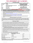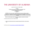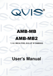
1
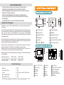
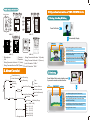
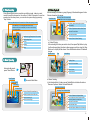
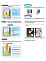
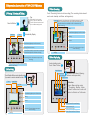
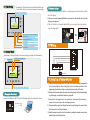
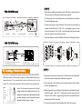
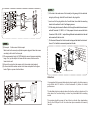
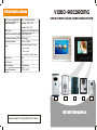
VIII.SPECIFICATIONS
Video-Recording
Switch Power Supply(SMPS)
100V~240V(50Hz/60Hz)
Power Consumption
Operation:6.5W±0.5W
Hand-Free Color Video Door Phone
Standby:1.5W±0.5W
Chime Tones
Dingdong/ 8 Chord Melody Rings
Audio Communication System Duplex Hand-Free
Automatically Shutdown Time
60 Seconds
Unlock Signal Output
12V/2A~100ms
Cable between Monitor & Camera:
Wiring
2
<50m: 0.5mm
2
>50m: 1.0mm
五、安全注意事项
Door Lock
Wiring: 18AWG, 1.0mm2
Video Format
ASF
Photo Format
JPG
Memory Storage
2 GB Maximum
Working Temperature
-100C to +400C
enter
MONITOR
exit
left
right
MENU
INSTRUCTION MANUAL
Designs Subject to Change Without Prior Notice.
SAFETY INSTRUCTION
1)DO NOT EXPOSE THIS DEVICE TO RAIN OR OTHER LIQUID;
2)POWER ON AFTER WIRING OF THE COMPLETE SYSTEM;
3)DO NOT DISMANTLE THE COVERS OR TRY TO SERVICE THE UNIT
WITHOUT TECHNICAL PERSON;
4)KEEP THE USER MANUAL AND OTHER ACCESSORIES WELL;
5)FOLLOW THE INSTRUCTION OF OPERATION AND INSTALLING
AFTERWARDS;
6)SOLDERING WELL OF THE JUNCTION END OF WIRES
FUNCTIONAL COMPONENTS
Ⅰ. 特殊功能:
INDOOR MONITOR VDP-C37DVR
Introduction of System
13
Welcome to use our DVR Video door phone, it will bring more security to
your family.
The DVR product with latest CCTV technologies bears Recording function of
videos or/and photos. We provide bulky memory to save all the video/photos
and you can keep the videos/photos for long time, and download
videos/photos to computer as one universal connector USB port is provided
to help you do this.
We provide friendly user-guide menu to help you operate and set the door
phone, videos/photos can be replayed, deleted, favorite ring melody can be
changed and time and date can also can set.
Apart from the recording function, it also bears basic function of clear dualway communication, unlock, alert, surveillance and night vision.
Please read the user manual before installing and wiring. Do retain it for
future reference. Hope our product satisfies you mostly.
1 7”LCD Screen
8 Wiring Terminals
2 Power Lamp
9 USB Port
3 Operation Lamp
10 Brightness Control
4 Microphone
11 Contrast Control
5 Speaker
12 Call Sound Volume Switch
6 Monitor
7 Menu
INDOOR MONITOR VDP-C33DVR
14
Please check your kit with this manual we have option of Video/Photo Memory
for this product.
Photo-Memory Only
□VDP-C37DP
Video-Recording Only □VDP-C37DVR
Photo/Video Both
□VDP-C37VP
□VDP-C33DP
□VDP-C33DVR
□VDP-C33VP
13 Talk Volume Switch
18
⑧
15
16
17
9 10 11 12 13
Checklist of package
□ 1PC
Outdoor Station;
□ 1PC
Cable;
□ 1PC(4-wire, usually 15 meters)
Mounting bracket;
□ 1PC
Mounting screws ;
□ 1PC
AC/DC Power Adaptor(N/A in Built-in Power supply Models) □ 1PC
Monitor ;
5.6-inch TFT-LCD
Microphone
Speaker
Monitor
Talking
Unlock
Warning
Returm
Up
Down
Menu
Confirm
Recording
Connecting Terminal strip
Brightness Adjustor
16 Contrast Adjustor
17 Ring Volume Adjustor
1 8 USB Port
OUTDOOR STATIONS
5 6 7 8 9 10
5 6 7 8 9 10
Screw Holes
1
1
2
4
III.Operation Instruction of VDP-C37DVR Series
1. Warning, Unlocking & Talking
2
3
3
Press Call Button
4
ODS-S □
ODS-5□
5 6 7 8 9 10
Automatically Display
1
Time
Video Icon
3
2
Close Monitoring(directly shut off the screen)
4
0 0 : 0 0 :14:53:02
16
02/15/2010
ODS-J□
① Microphone
③ Call
ODS-A□
② Camera ⑦ Wiring Terminal to Monitor “A”(Audio)
④ Speaker ⑧ Wiring Terminal to Monitor “+”(Power+)
⑤ Wiring Terminal to Monitor “V”(Video) ⑨ Lock Connector “UNL+”
⑥ Wiring Terminal to Monitor “GND”(Power-) ⑩ Lock Connector “UNL-”
Ⅱ. Menu Checklist
Close Monitoring
Monitor
Video Recording
Warning
Start Recording
Stop Recording
Play
Unlock(Electronically unlock the door and screen
will automatically close in 5s after unlocking.)
Talking(Talk with visitors)
Press Monitor Button under standby mode
if you want to monitor outside the door.
Pause
Stand-by
Video Files Playing
Volume Reduce
Time
Unread Videos
Total Files
Volume Increase
Video
Playback
Delete One(Selected)
Video Files Deleting
Video/Photo
Main Panel
: OK
Warning(Pressing this button 2 seconds, outdoor
camera will siren loudly)
2. Monitoring
Unlocking
Talking
Menu
M e mor y F u l l
SD
Stop Video Recording
close
stop
alarm
unlock
talk
Delete All
Close Monitoring(directly shut off the screen)
02/12/2010 13:50:02
Function Settting
Ring Setting
Time Setting
Storage check
1-9 Melody Rings
Year (1900~2100)
Month (01~12)
Day
(01~31)
Hour
(00~23)
Minute (00~59)
Second (00~59)
SD
: OK
01/007
Video Recording(Record what you are seeing as video)
close
record
alarm
unlock
talk
Warning (Pressing this button>2 seconds, outdoor
camera will siren loudly)
Unlock(Electronically unlock the door and screen
will automatically close in 5s after unlocking.)
Talking(Talk with visitors)
3. Video Recording
4.1.Video Playback
Press Record Button under monitoring or talking mode, video icon and
record time will be showed on the screen. It lasts 60 seconds if no action
operated on the door phone, you can also stop recording by pressing
“stop ”button
After accessing to the menu, a group(4/group) of thumbnail images of video
files are showed on the screen.
Recording Time of Selected Video
Video Series No.1
Selected Video is Highlighted in Yellow
Video Icon(Normally it is in Green and it is in Red when memory is <30M)
Once Memory is full, the system will automatically
delete the earliest records(20M) in order to make memory
for new recording.)
Play Video (press button again to pause
when playing.)
Video
play
back
delete
REC 00001
Select the Next Video
Close Monitoring(Directly shut off the screen)
00:00: 16
Memory Full
Select the Former Video
next
Time
02/12/2010 13:50:02
Exit Video Playback and back to Main Panel
exit
01.03.2098
07:00:06
close
stop
alarm
unlock
talk
Access to Panel of Video Deleting
Stop Recording Video
Warning
Unlocking
Talking
a. Videos Playing
After selecting the video you want to check, then press Play Button to play,
it will continuously play the video in time sequence until you stop it by Stop
Button or it will play all the videos. Press Exit Button to return to Thumbnail
images.
Play/Pause Icon
Volume Strip
Time
4. Menu Operating
video
02/27/2010
Under standby mode,
press “Menu” Button
Play/Stop Video
00:00:29
stop
exit
Return to Previous Menu
volvol+
Reduce Volume
Increase Volume
Video Playback
Function Settting
Access to Main Menu
Time Setting
b.Videos Deleting
In the thumbnails list of videos, press Delete Button to delete the videos.
There are 2 options: Delete One and Delete All.
Delete One or Delete All
Storage Check
Recording Time of Slected Video
Access to Panel of Selected Setting
enter
exit
left
right
Exit Main Panel and Shut Off Screen
Switch to Icons at Left
Switch to Icons at Right
Video
D e l et e O ne
Delete All
01.03.2098
07:00:06
Confirm to Delete the Selected Video
yes
exit
back
next
select
Return to previous menu; Return to Main
Panel when there is no video files.
Select the Former Video
Select the Next Video
Select the Options: Delete One or Delete All.
-2-
4.2. Function Setting You can select ring chime tones and video/
(B) 铃 声 选 择( Ringphoto
Setting
):
option
here
5. Computer Download
Connect the USB port with PC's with USB bridge cable to download the videos.
Function setting Current Ring
Save the Ring You Select and Return
to Previous Menu
USB Bridge Cable
Cancel the Current Ring Setting and
Return :
to Previous Menu
save
(A) 视
频回
放( Video
Function
setting:video/
photocancelplayback )
Ring setting:01
back
next
Move down to ring-selecting
Move up to function-selecting
6. Outdoor Station
( C )时Setting
间 设 置( T iAccessing
m e S e t tto
i nTime
g ) :Setting then press Select Button to set
4.3.Time
“year, month,
date,):
hour, minute and second” accordingly.
(B) 铃 声 选 择( Ring
Setting
Selected Part is highlighted
1. When a visitor presses Call Button, a confirming tone is heard which verifies the
call is going.
2. The person inside presses “Talk” Button to answer the call and talk with
the visitor through microphones.
3. The unit is built in infrared & white LEDs, you can see the visitors clearly even
at deep night.
Save Current Time Setting and Return
Previous Menu
Cancel Time Setting and Return
Previous:
Menu
save playback )
(A) 视 频 回
放( Video
02.27.2010
15:40:38
cancel
down
up
selcet
To Add Digits
To Less Digits
Select “Year, Month, Date, Hour,
Minute & Second” Part
( C )时 间 设
置( T i m e S e t t i n g ) :
4.4.Storage
Check
Accessing to Storage Check to check percentage of usage and total memory.
Used Memory
Total Memory in SD Card
(A) 视 频 回 放( Video playback ):
SD: 1 8 76MB
Use d : 73M
Return to Previous Menu (Main Panel)
exit
4. F o r O D S - J b e a r i n g 3 c a m e r a s a t t h e d o o r s t a t i o n g i v e s y o u 3 v i e w
direction(up, down right, down left) of visions which is much helpful for you to
identify visitors before opening your door.
IV.Operation Instruction of VDP-C33DVR Series
3. Video Recording
1. Warning, Unlocking & Talking
Tip:
Under basic function mode,
"Return, Up, Next, Menu and
Confirm" buttons don't work until
return to Menu-setting mode.
Press Call Button
Touch “Recording” button to start recording (The recording button doesn’t
work under standby and Menu-setting modes.)
Video Icon(Normally it is in Green and it is in Red when memory is <30M)
Memory is fnished(At this time, the system will automatically
delete the ealiest records(20M) in order to release memory
for new recording.)
Time
02/12/2010 13:50:02
Video Icon
Automatically Display
Time
00: 00:16
2106/02/07 06:28:15
MONITOR
Close Monitoring(directly shut off the screen)
TALK
Talking
Memory Full
UNLOCK
01/16/2010 00:
16:11:58
00:00:02
0 0 :16
MONITOR
Close Monitoring(directly shut off the screen)
ALARM
ALA R M
TALK
UNLOCK
ALARM
R ETU R N
UP
D OWN
MENU
CONFIRM
R ECORDING
RETURN
RET U R N
CONTROL
UP
NEXT
DO W N
MENU
MEN U
CONFIRM
CO N FIR M
Unlock
RECORDING
RE C O RDIN G
Recording(Touch this button to stop or
start recording)
Talking(Talk with visitors)
Unlock(Electronically unlock the door and screen
will automatically close in 5s after unlocking.)
Recording(Touch this button to stop or start
recording)
Warning
4. Menu Displaying
02/12/2010 13:50:02
0 0:0 0:16
2106/02/07 06:28:15
监视
通话
Warning(Touching this button>2 seconds, outdoor
camera will siren loudly)
2. Monitoring
Under standby mode,
Touch “Menu” Button
开锁
A LAR M
告警
C ON T ROL
N EX T
MENU
C O N FIRM
R ECO R DING
返回 上移 下移 菜单 确定 录像
Video Playback
Access to Main Menu:(following
can be operated)
Function Setting
Touch Monitor Button under standby mode
if you want to monitor outside the door.
Time
R E T URN
buttons
Time Setting
Storage Check
Unread Videos
MONITOR
Total Files
TALK
UNLOCK
01/16/2010 16:11:58
/ 024
00: 0 0 017
: 16
MONITOR
Close Monitoring(directly shut off the screen)
TALK
Talking
UNLOCK
Unlock
ALARM
AL A R M
RETURN
RE T U RN
CONTROL
UP
NEXT
DOW N
MENU
MENU
CONFIRM
CO N FIRM
Attention:
Under Menu-setting mode,
“Recording, Monitor, Alarm,
Unlock” buttons don’t work until
return to Monitor or Talk mode.
RECORDING
RE C O RDIN G
Access to Panel of Selected Setting
ALARM
R ETUR N
UP
D OWN
MENU
CONFIRM
Switch to Icons at Left
RECORDING
Recording(Touch this button to stop or
start recording)
Warning
Switch to Icons at Right
Exit Main Panel and Shut Off Screen
4.1 Video Playback
After accessing to the menu, a group(4/group) of thumbnail images of video
files are showed on the screen.
Video Series No.1
b.Videos Deleting
In the thumbnails list of videos, touch Delete Button to delete the videos.
There are 2 options: Delete One and Delete All.
Delete One or Delete All
Recording Time of Slected Video
Recording Time of Selected Video
Selected Video is Highlighted in Yellow
Video
MONITOR
Video
TALK
0 1 .03 . 209 8
0 7 :00 : 06
ALARM
RETURN
RETURN
CONTROL
UP
NEXT
MENU
DOWN
MENU
CONFIRM
TALK
01.03.2098
07:00:06
UNLOCK
REC 00001
ALARM
MONITOR
D l et e one
D le t e All
UNLOCK
RECORDING
CO N F IRM RECO R DING
ALARM
AL ARM
RETURN
RETUR N
CONTROL
UP
NEXT
DO WN
MENU
ME N U
CONFIRM
CONF I R M
RECORDING
RE COR D I NG
Play Video (Touch button again to
pause when playing.)
Access to delete panel
Select the Former Video
Confirm to Delete the Selected Video
Select the Options: Delete One or Delete All.
Select the Next Video
Select the Next Video
Select the Former Video
Return to Previous Menu
a.Videos Playing
After selecting the video you want to check, then touch Play Button to play,
it will continuously play the video in time sequence until you stop it by Stop
Button or it finishes playing off all the following videos. After playing,
touch Exit Button to return to Thumbnail images.
Play/Pause Icon
02/27/2010
video
Volume
Time
00:00:29
MONITOR
TALK
Return to previous menu; Return to Main
Panel when there is no video files.
You can select ring chime tones and video/
photo option here
4.2 Function Setting
Current Ring
Function setting
MONITOR
9(A) 视 频 回 放( Video playback ):
TALK
Function setting:vide/photo
Ring setting:01
UNLOCK
ALARM
RETURN
CONTROL
NEXT
MENU
CONFIRM
UNLOCK
RECORDING
ALARM
ALARM
RETURN
UP
DOW N
MEN U
RETURN
CONTROL
NEXT
MENU
CONFIRM
RECORDING
CO N FIRM RE C O RDIN G
AL A R M
Play/Stop Video
Reduce Volume
Increase Volume
Return to Previous Menu
RE T U RN
UP
DOW N
MEN U
CO N FIRM
RE C O RDIN G
Save the Ring You Select and Return
to Previous Menu
Move up to function-selecting
Move down to ring-selecting
Cancel the Current Ring Setting and
Return to Previous Menu
4.3 Time Setting
Accessing to Time Setting then touch Select Button to set
“year, month, date, hour, minute and second” accordingly.
Outdoor Station
1. When a visitor presses Call Button, a confirming tone is heard which verifies
Selected Part is Highlighted
the call is going.
TALK
2. The person inside presses Talk Button to answer the call and talk with the visitor
through microphones.
UNLOCK
3. The unit is built in infrared & white LEDs, you can see the visitors clearly
(A) 视 频 回 放( Video playback ):
监视
02 27 2010
15:40 38
菜单
MONITOR
even at deep night.
ALARM
ALARM
RETURN
RETU R N
CONTROL
UP
NEXT
DOWN
MENU
ME NU
CONFIRM
CON F I RM
RECORDING
save
RECOR D ING
cancel
down
Save Current Time
up
Previous Menu
select
Setting and Return
Select “Year, Month, Date, Hour,
Minute & Second” Part
To Less Digits
To Add Digits
Cancel Time Setting and Return
Previous Menu
V. Wiring
4.4 Storage Check
Accessing to Storage Check to check percentage of usage and total memory.
V
GND
Total Memory of the SD Card
Used Memory
A
+
MONITOR
(A) 视 频 回 放( Video playback
):
监视
SD:1876MB
Used:73M
TALK
菜单
ALARM
ALARM
RETURN
RETURN
CONTROL
UP
NEXT
DOW N
MENU
MENU
CONFIRM
UNLOCK
RECORDING
CO N FIRM REC O RDIN G
V
GND
A
+
UNL+ UNL-
Outdoor Camera
Indoor Monitor
Door Lock
VI. Installing of Indoor Monitor
1) Select a mounting location to an AC outlet but the monitor cannot be exposed to
Return to Previous Menu (Main Panel)
5. Computer Download
Connect the USB port with PC's with USB bridge cable to download the videos.
MONITOR
TALK
UNLOCK
ALA RM
R ET UR N
UP
D OW N
M E NU
C ON F IR M REC OR DIN G
USB Bridge Cable
dirt, direct sunlight(or other strong light), direct moisture conditions. After
determining the location, attach mounting bracket securely to the wall.
2) Drill a hole in the center area of the bracket just big enough for the electrical wiring
to pull through, and drill small holes for plug bolts.
3) Insert and fix the plug bolts in the small holes, then attach the mounting
bracket to the wall and fix with self-tapping screws.
4) Connect well the wires from Wiring Terminal and pull through the central hole
which connect to the Outdoor Station.
5) Attach the wired monitor unit to the bracket by setting the monitor over the four
bracket hooks and sliding it down.
1 ) ODS-S
VDP-C37DVR Series
① Dig a square hole which is the same size of the Flush Box in the wall and drill a
hole in the center for wiring and 2 small holes for plug bolts.
② Fix the plug bolts in the 2 small holes and put the Flush Box into the wall and
fix with 2 self-tapping screws.
Cable
③ Pull the wiring which connect to Monitor Unit through the central hole and
connect well with Terminals “V, GND, A & +”. Also prepare 2 wires to connect
with Lock Connectors “UNL+ & UNL-” and pull through Flush Box and central
① Plug Bolt
② Bracket
③ Self-Tapping Screws
④ Hook Holes
hole in the wall and connect with the door lock.
④ Put the wired Camera Unit in the Flush Box and fix with 2 Hex Socket Cap Screws.
VDP-C33DVR Series
Put-in
Cable
Hex Socket Screw Key
(Provided)
1.Bracket plate for indoor section
2.Plastic Expansion plug
Flush Box
3.Fixing screw
4.Holes for Hanging indoor section
VII. Installing of Outdoor Station
The monitor is compatible with several camera units (ODS-J/ODS-S/ODS-5
ODS-A are optional.). Please verify the model no. before installation and follow
2 ) ODS-5
① Dig a square hole which is the same size of the Flush Box in the wall and drill
a hole in the center for wiring and 4 small holes for plug bolts.
correct directions. The recommended location of camera unit is at the
height 150~170cm from central part of Camera to the floor (for reference only).
② Fix the plug bolts in the 4 small holes and put the Flush Box into the wall and
fix with 4 self-tapping screws.
Notes: Do not expose the camera unit to direct
1.5-1.7m
sunlight and be sure it is shield from storm rain. The
background of visitors may be affected by street lamp
and other strong light, you can mount some lamps to
highlight for clearer images of visitors.
③ Pull the wiring which connect to Monitor Unit through the central hole and connect
well with Terminals “V, GND, A & +”. Also prepare 2 wires to connect with Lock
Connectors “UNL+& UNL-” and pull through Flush Box and central hole in the
wall and connect with the door lock.
④ Put the wired Camera Unit in the Flush Box and fix with 4 drive screws.
4) ODS-J
① Drill a hole in the center area of the bracket just big enough for the electrical
wiring to pull through. And drill 2 small holes for the plug bolts.
Put-in
② Insert and fix the plug bolts in the 2 small holes, then attach the mounting
Cable
bracket to the wall and fix with 2 self-tapping screws.
③ Pull the wiring which connect to Monitor Unit through the central hole and connect
Flush Box
Driv
rew
e Sc
s
well with Terminals “V, GND, A & +”. Also prepare 2 wires to connect with Lock
Connectors “UNL+ & UNL-” and pull through Bracket and central hole in the wall
and connect with the door lock.
④ Put the wired Camera Unit in the bracket and pop out the tab at the bottom of
3 ) ODS-A
the unit. Fix it with drive screw and press back the tab.
(1)Frame part :Surface-mount the frame part
Make holes for the screw by wall plastic expasion plug and fasten the screws
according to the hole of the frame part.
(2)The recommended height of 150CM helps the camera for proper monitoring
range. First , put the clasp in the frame with four screws, then secure the
frame into the wall.
(3)Connect the wires from the camera unit to the monitor wiring terminal.
(4)In the end install the outdoor section in the frame as depicted on the figure
below. Tighten up screw from the bottom.
B ra c k e
t
C ab le
P u t - in
Drive Screw
Self-Tapping Screws
Pop-out Tab
Attention:
Screw
It is suggested that owners delete photos kept regularly for photo-memory
only model with SD built-in to hold thousands of photos for better
performance.
The handled objects are photos when the function setting is photo and it is
video when the function setting is video for photo/video both recording
model.
plastic
expansion
plug
The system should be power off each time to refresh after downloading
files by the USB port for all the video door phone models with memory
function.