1
GEN II
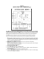
QUICK START AND COMMISSIONING
Follow these Quick steps for a successful job
If you need additional information, please read the GEN II Manual
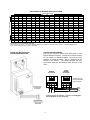
1. Install GEN II Controller in an easily accessible location for your customer.
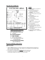
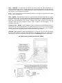
2. Install an Independent 24 Volt 40 VA transformer, and connect to the TR1 and TR2 terminals
on the GEN II controller.
3. Install the LAT sensor in the supply air, ahead of any bypass takeoffs. Wire sensor to the S S
terminals on the GEN II controller.
4. Install Dampers and Bypass Dampers.
5. Install all thermostat sub-bases.
6. Wire R & C Terminals from the GEN II Controller to the first sub-base – only (18 ga.
Thermostat wire).
7. Wire RX & TX Terminals from the GEN II Controller using Belden 8740 twisted pair wire to
the first thermostat sub-base – only.
8. Damper wiring – connect RO, RC, MC wires from each thermostat to its damper with 18 GA
thermostat wire.
9. Plug 1 MODSTAT into that sub-base.
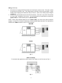
10. Address that thermostat to #1 – see Pages 10-13 for MODSTAT installation, addressing and
operation.
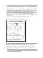
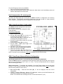
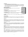
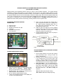
11. Turn on GEN II Controller switch “E”. Power light should light up and then look at the Display
"O" on the GEN II Controller, and the number 01 appears on the Display. This indicates you
are communicating with the first thermostat.
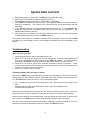
12. If you don’t see the #1 and a 0 is displayed, check the address. If the address is #01, then
check wires for R&C polarity and RX TX for correct connections.
13. If #1 is displayed on the GEN II Controller, then daisy chain wires from Stat 01 to the next stat
and address it #2; then repeat the ON – Off switch operation and confirm the #2 shows up on
the display indicating the system is now communicating with 2 thermostats.
14. Continue adding MODSTATS, and confirm communication by repeating the ON – Off switch
operation until all stats are wired and the total number of thermostats on your job shows up
on the display on the GEN II Controller. (If you are adding stand-alone units to the GEN II
Controller, see #15. If not, skip to #16)
15. If there are any stand-alone units that are going to be managed by the GEN II Controller,
install DIGICOM / DIGIHP stats at this time. Continue the RX & TX daisy chain from the last
MODSTAT to the DIGICOM / DIGIHP and wire in the stand-alone unit at this time and
address the DIGICOM / DIGIHP (see Pages 14-17 for installation, addressing and
operation). Confirm communication by repeating the On – Off switch operation until all stats
are wired and the total number of thermostats on your job shows up on the display on the
GEN II Controller.
16. Go to any MODSTAT and make a Cool Call. Look at the GEN II Controller and confirm Y1
(yellow LED) and G (green LED) lights are on.
17. Turn off the Cool Call to be sure Y1 and G turn off at GEN II Controller.
18. Repeat with Heat Call for W1 (red LED).
19. Wire GEN II Controller to A/C unit.
20. Set stat to call for cool, and check register to be sure each damper opens and closes as you
make and satisfy calls.
For Advanced Feature Configuration or additional operating information, review the attached
GEN II Manual.
ONLINE Step-by-Step Installation Instructions and Commissioning
www.zonexcontrols.com/gen.html













![[U4.84.01] Opérateur COMB_SISM_MODAL](http://vs1.manualzilla.com/store/data/006353312_1-84c0f0aa2b85e6ab7465faa950d278b0-150x150.png)
![[U4.84.01] Opérateur COMB_SISM_MODAL](http://vs1.manualzilla.com/store/data/006354551_1-0a996585a4efb054f257f659270030c7-150x150.png)
![[U4.84.01] Opérateur COMB_SISM_MODAL](http://vs1.manualzilla.com/store/data/006369926_1-bf5f185851d150b3bc2e73af807f0eaf-150x150.png)