1
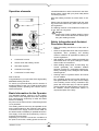
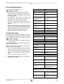
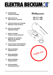
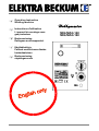
G
Operating Instruction
Welding machine
F
Instructions d'utilisation
L’appareil de soudage sous
gaz protecteur
N
Bruksanvisning
Dekkgass-sveiseapparatet
J
Käyttökäsikirja
Parhaat onnittelumme tämän
korkealaatuisen
S
Bruksanvisning
skyddsgassvets
MIG/MAG 140
MIG/MAG 160
Great Britain
Please return the enclosed warranty card to us.
Retain proof of purchase! You are only entitled to claim warranty against
proof of purchase.
Please see back cover for manufacturer representative´s address nearest you.
1.
France
SVP, retournez-nous la carte de garantie jointe.
Conservez le reçu d'achat! La garantie ne peut être accordée que sur
présentation de ce reçu.
Vous trouverez l'adresse de votre représentant le plus proche à la dernière page de couverture.
2.
N
Norge
Send vedlagte garantikort tilbake til oss.
Oppbevar kvitteringen!
Garantiytelser skjer kun på grunnlag av forelagt kvittering.
Adressen til ditt nærmeste serviceverksted finner du bak på siste
omslagside.
3.
J
Suomi/ Finland
Ole hyvä ja palauta oheinen takuukortti meille.
Säilytä ostokuitti!
Takuu on voimassa vain kuittia vastaan.
Lähimmän edustajan osoite löytyy takakannesta.
4.
S
Sverige
Återsänd medföljande garantisedel till oss.
Förvara kvittot!
Garantianspråk erkännes endast mot uppvisande av kvitto.
Adressen till närmaste representant finns på bakre uppslagets insid.
5.
G
F
Redaktion: Zindel • Technische Dokumentation und Multimedia • D-22417 Hamburg
XS0006E.fm
1Great Britain
Operation elements
cause disturbances to other consumers in the distribution system. Check with your power utility before
connecting to power.
Keep the welding machine out of the reach of children.
1
Please note the hazards associated with the welding process and observe any work and fire prevention regulations.
The welding machine is not suitable for outdoor use
in rain. Store in a dry place.
2
3
4
5
1
Connection for torch
2
Switch on/off and welding currant
3
Wire feed regulator
4
Overload control light
5
Connection for earth clamp
Dear customer,
Congratulations to your purchase of this high-quality
MIG/MAG welding machine.
To ensure your personal safety and for reasons of
appliance safety we ask you to read the instructions
completely before operating this machine and to
observe all points.
A Danger!
person with a heart condition wearing a pace
maker must contact their doctor before operating this welding machine.
Safety Information and Accident
Prevention Measures
· Keep the welding machine out of the reach of
children.
· Observe all applicable work and fire prevention
regulations when operating this welding
machine. Observe all applicable accident prevention regulations.
· With welding a number of different hazards are
associated, which can pose a danger to health
under certain circumstances.
· When welding always wear a close fitting, dry
overall (preferably fire retardant welders
apparel) unsoiled by combustible substances,
sturdy, insulating boots, headgear and leather
welders gloves.
· Clothing made of synthetic fabrics and shoes
are not suitable.
Dry, insulating gloves worn on both hands protect against electric shock (open-circuit voltage
of the welding current circuit), hazardous rays
(heat and ultra-violet rays) as well as against
glowing metals and slag spatters. The ultra-violet radiation causes sunburn-like effects on
unprotected parts of the body.
Basic Information for the Operator
The MIG/MAG welding machine is a DC welding
power source with integrated wire feed, designed
and manufactured exclusively for MIG and MAG
electric arc welding.
Any other use of this machine involves dangers and
is not permitted.
The welding machine must only be operated on the
mains voltage stated on the machine's rating plate.
Connection to the supply circuit must be made via
an earthed outlet, installed by a qualified electrician.
The supply circuit must be protected by a fuse or
miniature circuit breaker.
Depending on the mains connection conditions at
the point of connection, welding power sources can
MIG/MAG 140/160
1.1
Fumes – Vapours – Smoke
Fire
· During welding hazardous smoke and metal
dust develops. We strongly recommend the
wearing of welding fume respirators, and to weld
only in sufficiently vented rooms, to ensure the
necessary operator protection.
· For enclosed spaces forced ventilation, installed
below the welding area, must be used.
· The material to be welded must be free from halogen solvents or degreasing agents, to prevent
the generation of toxic vapours.
· Metals coated with lead, graphite, cadmium,
zinc, mercury or beryllium, or containing any of
these materials, can generate much smoke during welding.
A Danger!
The arc temperature is approx. 2400 ˚C.
· Welding releases ozone, which is a type of oxygen that can lead to irritation or disorder of the
respiratory organs.
· Degreasing agents such as trichlorethylene, tetrachloroethylene etc. vaporise during welding
and are chemically converted into phosgene.
Phosgene is poisonous!
UV-Rays
· The arc radiation can cause eye damage and
skin burns.
· For protection against sparks, heat, visible and
invisible rays suitable eye protection gear (welding visor or helmet with standardised filter
lenses to class 10 – 15 of DIN 4647, depending
on welding current) must be worn.
· Do not look into the arc with unprotected eyes
(risk of blinding and burns). The invisible ultraviolet radiation causes, with insufficient eye protection, a very painful conjunctivitis, which
appears only hours later.
· Weld only within the range of visibility of other
persons, who can assist you in an emergency.
· Other persons or helpers near the arc must be
made aware of the hazards, and equipped with
the necessary protective gear.
· Neighbouring workplaces are to be screened off
to provide protection against radiation.
· When welding inside rooms and buildings sufficient ventilation must be ensured.
1.2
Before starting to weld observe the following information:
· Remove all combustible materials and objects
within a radius of 5 m from the welding point.
· Materials that can not be removed within a 5 m
radius must be protected by covering with sheet
metal, wet cloths etc.
· Any wall openings, cracks and the like must be
covered or sealed respectively, to prevent
uncontrolled flying of sparks.
· Keep fire extinguishing equipment such as fire
extinguisher, water pale etc. at hand.
· Keep in mind that by heat dissipation from the
welding point a fire may be started on covered
parts or in other rooms respectively.
· After completion of the welding work check the
vicinity of the welding point several times within
a period of 6 – 8 hours for heat conduction,
glowing combustion spots, hidden seats of fire
etc.
Handling of Shielding Gas Cylinders
· Observe all applicable regulations pertaining to
the handling of gas cylinders. Because of the
dangerously high internal pressure (up to 200
bar) shielding gas cylinders are to be specially
protected against mechanical damage, falling
over or falling down, heating up (max. 50˚C),
prolonged radiation by sunlight and heavy frost.
· When the welding machine is equipped with a
gas cylinder too large in size this can cause, on
uneven ground, the welding machine to fall
over. To prevent subsequent damage to the
welding machine or the gas cylinder, use only
proper size gas cylinders (10l / 20l cylinders).
· Have cylinders refilled only by authorised filling
stations.
MIG/MAG 140/160
Electrical Hazards
· The connection to power mains and servicing of
the welding machine is to be done in accordance with VDE regulations or other standards
applicable in your area.
· Ensure proper protective bonding of the supply
circuit.
· Ensure proper protective bonding of the workbench.
· Any service or maintenance work must only be
carried out by qualified personnel.
· Replace defective or damaged parts of torch or
torch leads without delay.
· The unit must only be connected to an earthed
outlet as a matter of principle. Only connections,
including outlets and extension cables with an
earthed plug, having an earth conductor and
installed by a qualified electrician, are permitted.
· The fuse protection of the supply circuit must be
in accordance with local regulations. According
to these regulations fuses or miniature circuit
breakers respectively, suitable for the conductor
cross section, must be installed. Installation of a
fuse with to high an ampere rating may cause
line fire and subsequent fire damage to the
building.
· Replace damaged torch insulation and welding
cables without delay.
· Replacement of a damaged power cable, plug
etc. and repairs to the electrical components of
the welding machine must be left to a qualified
electrician.
· Welding torches must not be held in an armlock,
or in such way that electricity can run through
the body.
· Switch the unit off for longer work breaks.
Unplug when work is completed and before relocating the unit. In case of accidents separate the
welding power source at once from the power
supply.
General Machine Description
The MIG/MAG welding machine consists of a transformer, a series-connected silicon rectifier, a welding circuit choke, and a wire feed unit.
The welding machine is suitable for the welding of
different electrode wires (e.g. steel, see "Technical
Specifications") under a shielding gas cover (CO2,
mixed gas and argon).
The machine is fan cooled and has an overload protection.
MIG/MAG 140/160
Commissioning
Taking out of enclosed parts
All enclosed parts are inside the wire feed compartment and can be taken out after the wire feed compartment cover is removed..
Installation Conditions
The MIG/MAG welding machine is to be set up in
dry surroundings with enough space to ensure sufficient cooling. The welding machine is designed for
indoor use. It must not be use outdoors in rain.
Mains connection
· Check to see that mains voltage matches the
voltage shown on the machine's rating plate.
· Set welding step switch to "0" before plugging
in.
Shielding gas cylinder connection
· Place gas cylinder onto the welding machine's
cylinder rack and secure with the chain to the
cylinder holder at the rear of the unit. Take off
the cylinder cap and open cylinder valve briefly,
facing away from your body.
· Screw pressure reducer to the gas cylinder
valve. Run gas hose from pressure reducer to
gas inlet port of the unit.
· Recommended gas flow rate in draft-free
rooms: 5-10 l/min.
· When using adjustable pressure reducers set
flow rate according to litre scale in the clock with
the T-screw. Turning the T-screw in increases
the gas flow rate, turning it out reduces the gas
flow rate.
· While setting the gas flow rate, the unit must be
switched on and the torch's trigger switch held
down, so the solenoid gas valve is open. To prevent wasting electrode wire swing the wire feed
unit's leaf spring to the side.
Modifications and repairs to pressure reducers are
strictly prohibited due to the hazards involved. Send
faulty pressure reducers to a service centre.
1.3
Earth lead connection
Connect earth clamp of the unit's earth cable as
close as possible to the welding point. Ensure good
metal to metal contact.
Preparation of the welds
The joint section of the workpieces to be welded
must be free of colour, metall covering, dirt, rust,
grease and humidity.
The preparation of the welds is to be done under
observation of all welding techniques regulations.
Hints for Setting and Welding
Techniques
Switching the unit on
The unit is switched on with the combination ON/
OFF – welding step switch. With the switch in the
"0"- position the unit is electrically separated from
the power supply.
The unit is fitted with an embedded temperature
detector, which shuts the unit down in case of an
thermal overload.
Form of joint
s
I-joint onesided
I-joint on both
sides
b
V-joint
s
25
b
K-joint
s
Double-K-joint
Setting the welding parameters
After preparation of the welding machine the welding can begin.
To do so, welding voltage and wire feed have to be
matched to suit the welding task. If the wire feed
speed is increased the welding current increases
accordingly.
For every electrode wire diameter and every welding task optimal parameters can be found. They are
recognisable at the typical humming sound of the
arc, amongst other.
If there is too much deviation from the optimal
parameters, a satisfactory welding is not possible.
The right joint
The list gives hints for the shaping of the joints.
Execution
Platethickness
s (mm)
Gapwidth
b (mm)
< 1,5
> 1,5
0
<2
2–4
<2
3–6
<1
3–6
<1
> 0,6
–
0,6 – 1,5
–
> 0,6
–
>1
–
s
Cornerjoint
The tripping of the thermal overload protector is indicated by the front panel control light. Welding power
source and wire feed are temporarily disabled.
After cooling down the welding power source is
automatically activated again, the control light extinguishes.
1.4
MIG/MAG 140/160
Care and Maintenance
The unit is nearly maintenance-free.
– Voltage!
B Danger
Disconnect from power before servicing!
· Check feed roller, pressure roller and wire leadin nozzle at regular intervals for dirt build-up,
clean if necessary.
· At appropriate intervals the complete torch
including torch leads should be cleaned, as
rubbed-off parts and dust build-up inside.
· The torch's contact tip is a wearing part. If its orifice has enlarged the contact tip must be
replaced.
· On the inside of the plug-on gas shroud spatters
build up. These have to be removed when necessary. An anti-spatter spray eases this job and
keeps spatters from sticking to the shroud.
· Replace damaged cables without delay.
Trouble Shooting
Mechanical faults are mostly indicated by an irregular or completely blocked wire feed. Electrical faults
cause a malfunction of the unit, in part or complete.
- Voltage!
B Danger
Electrical fault finding must be left to a qualified electrician.
Further fault finding can proceed according to the
wiring diagram supplied.
Fault find should first start with the unit de-energized, and in the following order:
1. Check of the power supply cable connection
and all other connections on switches, transformer and choke, as well as all plug-and-socket
connections and soldered connections for tightness.
2. Check of fuse for continuity and contact.
3. Visual check for possible shorts or overloads of
windings (discoloring).
Fault, Likely causes
Remedy
• Noisy or unstable arc?
Incorrect welding voltage
Correct with welding step
switch
Too much/too little wire
feed
Correct with wire feed pot
Earth clamp loose or
high contact resistance
(rust, paint)
Ensure good contact
between earth clamp and
workpiece
Contact tip worn or
incorrect diameter
Replace
Incorrect gas flow rate
setting
Correct
Workpiece not clean in
seam area
Remove paint, rust, grease
etc.
Power unit faulty
Have machine checked by
service centre
Spiral liner dirty
Clean or replace
Wire feed faulty
See below
• Excessive spattering
Wire feed rate too high
Correct with wire feed pot
Welding voltage too
high
Correct with welding step
switch
Workpiece not clean
Clean
• Wire feed motor does not run
No power
Check power supply
Welding step switch in
"0" position
Set to a welding step
Torch trigger switch not
activated
Activate torch trigger switch
Fuse blown
Have replaced by a qualified
electrician
Motor faulty
Have repaired by service
centre
• No wire feed
Pressure roller loose
Increase pressure of leaf
spring with knurled thumb
screw
Wire kinked at wire
feed
Adjust wire lead-in nozzle
Groove in feed roller
worn
Replace
Electrode wire stuck to
contact tip
Replace contact tip, if wire is
deformed, reduce pressure
of pressure roller
• Machine shuts down, overload control light
comes on
MIG/MAG 140/160
Duty cycle exceeded
Let machine cool down,
observe duty cycle stated on
nameplate
Power unit faulty
Have repaired by service
centre.
1.5
Technical Specification
MIG/MAG 140
MIG/MAG 160
Power supply
1 x 230 V, 50/60 Hz
1 x 230 V, 50/60 Hz
Power input max.
4,4 kVA
4,4 kVA
Current draw max.
21 A
20 A
Mains fuse, time-lag
16 A
16 A
Open-circuit voltage
17,5 – 28 V
19 – 30 V
Welding current range
30 – 140 A
30 – 160 A
max. Duty cycle at 145 A
7%
15 %
Welding steps
4
4
Wire feed rate
1,0 – 12 m/min
1,0 – 12 m/min
Electrode wire diameter
0,6 – 0,8 mm
0,6 – 0,8 mm
Insulation class
N
N
Protection class
IP 21
IP 21
Length x Width x Height
590 x 260 x 420 mm
590 x 260 x 420 mm
Weight
26 kg
28 kg
Circuit diagram
S1
L1
max
Ø
min
1B
S2
1
1
1
2
1A
4
1B
3
L1
T1
L1
A
2
2A
1
C
2
1
T1
U1
L1
A
M1
N
N
2
2
B
2
S1
6
1A
2B
1
1
3
3
4
3
6
4
B
U1
S2
S3
M1
10
11
H1
H1
12
TH
TH
3
3
M2
2
5
4
M2
L1
2
5
4
L1
P1
P1
TV
TV
VA R - 0 3
VA R - 0 3
1
N1
N1
1
N
N
MIG/MAG 140
1.6
MIG/MAG 160
MIG/MAG 140/160
B
Belgium
Elektra Beckum Belgium N.V.S.A.
Industriezone
Hofte te Bollebeeklaan
B-1730 Asse-Mollem
Tel.: 0032-24540454
Fax: 0032-24540450
D
Deutschland
G
I
Elektra Beckum AG
Daimlerstraße 1
D-49716 Meppen
Tel.: 01803-333 456
Fax: 01803-333 457
K
Danmark
Elektra Beckum Danmark
Lundeborgvej 9
Postbox 8113
DK-9220 Aalborg OE
Tel.: 0045-98-151300
Fax: 0045-98-151451
E
España
France
N
H
Suomi/ Finland
Nofa OY
P.O.Box 28
Hannuksentie 1
FIN-02270 Espoo
Tel.: 00358-9804-861
Fax: 00358-9803-9485
MIG/MAG 140/160
Italia
Norge
Profilma-Import A/S
Postboks 536 Nanset
Sophus Buggesvei 48
N-3252 Larvik
Tel.: 0047-33114777
Fax: 0047-33114108
Nederland
Elektra Beckum Nederland
Einsteinstraat 15
NL-1704 RT Heerhugowaard
Tel.: 0031-7257-44660
Fax: 0031-7257-44250
P
J. Muller
1.Place de Lábattoir
F-67190 Mutzig
Tel.: 00333-88479971
Fax: 00333-88479970
J
Elektra Beckum Machinery Ltd.
6 The Quadrangle
Premier Way
GB-SO51 9AQ Romsey
Tel.: 0044-1794-834900
Fax: 0044-1794830083
Elektra Beckum AG Germania
Daimlerstraße 1
D-49716 Meppen
Tel.: 0049-1803-333456
Fax: 0049-1803-333457
Elektra Beckum Import S.A.
Calle Alejandro Coicoechea 6
E-08960 Sant Just Desvern
Tel.: 0034-9-34739009
Fax: 0034-9-34739755
F
Great Britain
Portugal
Costa & Garcia S. A.
Vilar do Paraíso, Ap. 23
P-4408 Valadares
Tel.: 00351-2-7121279
Fax: 00351-2-7124670
S
Sverige
HDF-Paulsson AB
Box 525
Svaravaregatan 5
S-30180 Halmstad
Tel.: 0046-35-154400
Fax: 0046-35-121780
115 164 4534 GB/F/N/SF/S 3298 1.0