1
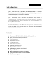
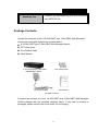
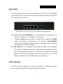
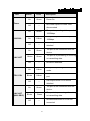
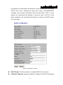
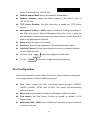
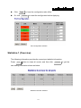
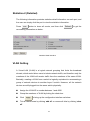
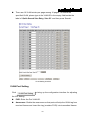
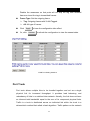
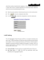
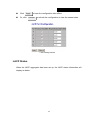
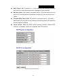
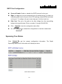
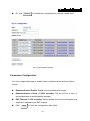
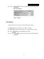
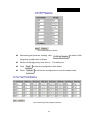
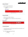
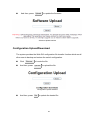
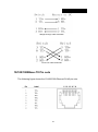
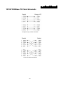
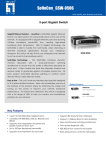
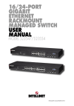
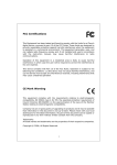
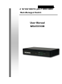
4 10/100/1000TX plus 1 MINI GBIC Web Managed Switch User Manual MS453510M CE Mark Warning This is a Class-A product. In a domestic environment this product may cause radio interference in which case the user may be required to take adequate measures. Content CE Mark Warning ................................................................................................. 2 INTRODUCTION ............................................................................... 1 Features ............................................................................................................... 1 Software Feature .................................................................................................. 2 Package Contents ................................................................................................ 3 HARDWARE DESCRIPTION ............................................................ 4 Physical dimension .............................................................................................. 4 Front Panel........................................................................................................... 4 Rear Panel ........................................................................................................... 5 LED Indicators...................................................................................................... 5 Desktop Installation .............................................................................................. 7 Attaching Rubber Feet .................................................................................. 7 Power On ............................................................................................................. 7 NETWORK APPLICATION ............................................................... 8 Small Workgroup .................................................................................................. 8 Segment Bridge ................................................................................................... 8 WEB-BASED MANAGEMENT ....................................................... 10 About Web-based Management ......................................................................... 10 System Login ..................................................................................................... 10 System Configuration ......................................................................................... 11 Port Configuration .............................................................................................. 13 Statistics-1 (Overview) ....................................................................................... 14 Statistics-2 (Detailed) ......................................................................................... 15 VLAN Setting...................................................................................................... 15 VLAN Port Setting ....................................................................................... 16 Port Trunk .......................................................................................................... 17 LACP Setting...................................................................................................... 18 LACP Status....................................................................................................... 19 Spanning Tree ................................................................................................... 20 RSTP System Configuration ....................................................................... 20 RSTP Port Configuration ............................................................................ 22 Spanning Tree Status ........................................................................................ 22 802.1X Configuration ......................................................................................... 23 Parameters Configuration ........................................................................... 24 QoS Setting ....................................................................................................... 25 System Restart .................................................................................................. 28 Factory Default .................................................................................................. 28 Firmware Upload ............................................................................................... 28 Configuration Upload/Download ........................................................................ 29 TROUBLESHOOTING .................................................................... 31 Incorrect connections......................................................................................... 31 Faulty or loose cables ......................................................................... 31 Non-standard cables ........................................................................... 31 Improper Network Topologies ............................................................. 32 Diagnosing LED Indicators ................................................................................ 32 TECHNICAL SPECIFICATION ....................................................... 33 APPENDIX ...................................................................................... 36 10 /100BASE-TX Pin outs ................................................................................. 36 10/100Base-TX Cable Schematic ...................................................................... 36 10/100/1000Base-TX Pin outs ........................................................................... 37 10/100/1000Base-TX Cable Schematic ............................................................. 38 Introduction The 4 10/100/1000T plus 1 Mini-GBIC Web Managed Switch is a multi-port Switch that can be used to build high-performance switched workgroup networks. The Switch is targeted at workgroup or department. The 4 10/100/1000T plus 1 Mini-GBIC Web Managed Switch features a “store-and-forward “ switching scheme that offers low latency for high-speed networking and allows the switch to auto-learn and store source address in a 8K-entry MAC address table. The 4 10/100/1000T plus 1 Mini-GBIC Web Managed Switch has 4 auto-sensing 10/100/1000 Base-TX RJ-45 ports plus one MINI GBIC slot that enables extended distance connection. Features Conforms to IEEE 802.3, 802.3u, 802.3ab, 802.3x and 802.1x Store-and-Forward switching architecture Web Management Auto-MDIX on all ports 10Gbps back-plane N-Way Auto-Negotiation Supports Port Based VLAN Supports Class of Service Supports STP (Spanning Tree Protocol) Supports Port Trunk Back pressure with half duplex (10/100Mbps) Flow control with full duplex (10/100/1000Mbps) Web Firmware upgrade 1 8K MAC address table 112Kbytes memory buffer True non-blocking switching 8K Jumbo Frame supported Software Feature Management Web Management Firmware update Web UI firmware update One default button for system default System default Default IP: 192.168.16.1 Gateway: 192.168.16.254 Subnet Mask: 255.255.255.0 IEEE802.3ad port trunk with link aggregation Port Trunk control protocol (LACP) The trunk group up to 2 and maximum trunk port member up to 2 ports. Port Based VLAN VLAN VLAN ID up to 5 VLAN group up to 5 DHCP DHCP client feature Port based Quality of Service Tag based IPv4 ToS Class of Service Per port supports 4 priority queues 2 Spanning Tree IEEE802.1w rapid spanning tree and compatible with IEEE 802.1d Package Contents Unpack the contents of the 4 10/100/1000T plus 1 Mini-GBIC Web Managed Switch and verify them against the checklist below: 4 10/100/1000T plus 1 Mini-GBIC Web Managed Switch DC Power Cord Four Rubber Pads User Manual 4 10/100/1000 plus 1 Mini-GBIC Web Managed Switch Four Rubber Pads DC Power Adapter User Manual Package Contents Compare the contents of your 4 10/100/1000T plus 1 Mini-GBIC Web Managed Switch package with the standard checklist above. If any item is missing or damaged, please contact your local dealer for exchanging. 3 Hardware Description This section mainly describes the hardware of the 4 10/100/1000T plus 1 Mini-GBIC Web Managed Switch, and gives a physical and functional overview on certain switch. Physical dimension The 4 10/100/1000T plus 1 Mini-GBIC Web Managed Switch physical dimension is 165 x 100 x 32.5 mm (W x D x H). Front Panel The Front Panel of the 4 10/100/1000T plus 1 Mini-GBIC Web Managed Switch consists of LED Indicators and a reset button. Please refer to LED Indicator section for LED description. Reset button: It provides an easy way for user to reset the configuration back to the default settings. Press the button more than 5 seconds, and then the switch will restart and set all configurations back to the default settings. 4 Rear Panel The rear panel consists of the 4 10/100/1000Base-TX RJ-45 port, one Mini GBIC slot, and DC Power Jack as shown in the figure below. The switch will work with DC in the range of 12V/0.8A. The Rear Panel of 4 10/100/1000T plus 1 Mini-GBIC Web Managed Switch RJ-45 Ports (Auto MDI/MDIX): 4x 10/100/1000 N-way auto-sensing for 10Base-T, 100Base-TX or 1000Base-T connections. In general, MDI means connecting to another Hub or Switch while MDIX means connecting to a workstation or PC. Therefore, Auto MDI/MDIX would allow connecting to another Switch or workstation without changing non-crossover or crossover cabling. Mini GBIC slot: The appropriate replaceable Mini-GBIC port is available with a variety of different transmitter and receiver types, allowing users to select the appropriate transceiver for each link to provide the required optical reach over the available optical fiber type. There is one LED indicator—LNK/ACT—for Mini-GBIC port on the front panel. LED Indicators The LED Indicators display the real-time information of systematic operation status. Please see definition of the LED indicators as follows. 5 LED Status Color Description On Green Power On Off -- On Green On Yellow Off -- On Green Blinks Green Off -- On Yellow Blinks Yellow Off -- On Green Power 100/1000 LNK /ACT FDX /COL LNK /ACT (MINI GBIC) Blinks Off No Power inputs or Power cord disconnected The port is operating at the speed of 1000Mbps. The port is operation at the speed of 100Mbps. In 10Mbps mode or no device attached The port is well connected with the device. The port is in processing of receiving or transmitting data. No device attached. The port is operating in Full-duplex mode. Collision of Packets occurs in the port. Half-duplex mode or no device attached. The port is well connected with the device. Green The port is in processing of receiving or transmitting data. No data transmitted or no device -- connected The Definition of LED Indicators 6 Desktop Installation Set the switch on a sufficiently large flat space with a power outlet nearby. The surface where you put the switch should be clean, smooth, level and sturdy. Make sure there is enough clearance around the switch to allow attachment of cables, power cord and allow air circulation. Attaching Rubber Feet A. Make sure mounting surface on the bottom of the switch is grease and dust free. B. Remove adhesive backing from your Rubber Pads. C. Apply the Rubber Feet to each corner on the bottom of the switch. These footpads can prevent the switch from shock/vibration. Power On Connect the power adaptor to the power jack on the rear panel of the switch. The other side of power adaptor is connected to the power outlet. The external power supply in the switch works with DC power in 12V/0.8A. Please check with the power indicator on the front panel to see if power is properly supplied. 7 Network Application This section provides user a few samples of network topology in witch the switch is used. In general, the 4 10/100/1000T plus 1 Mini-GBIC Web Managed Switch is designed as a segment switch. That is, with its address table (8000 MAC address) and high performance, it is ideal for interconnecting networking segments. PC, workstations, and servers can communicate each other by directly connecting with 4 10/100/1000T plus 1 Mini-GBIC Web Managed Switch. The switch automatically learns nodes address, which are subsequently used to filter and forward all traffic based on the destination address. By using Uplink port, the switch can connect with another switch or hub to interconnect other small-switched workgroups to form a larger switched network. Meanwhile, you can also use fiber ports to connect switches. The distance between two switches via fiber cable depends on the type of fiber transceiver. Small Workgroup The 4 10/100/1000T plus 1 Mini-GBIC Web Managed Switch can be used as a standalone switch to which personal computers, server, printer server, are directly connected to form small workgroup. Segment Bridge For enterprise networks where large data broadcasts are constantly processed, this switch is an ideal solution for department users to connect to the corporate backbone. 8 Two 4 10/100/1000T + 1 Mini-GBIC Web Managed Switches with PCs, print server, and local server attached, are both connected to the core switch. All the devices in this network can communicate with each other through the 4 10/100/1000T plus 1 Mini-GBIC Web Managed Switch. Connecting servers to the 4 10/100/1000T plus 1 Mini-GBIC Web Managed Switch allows users accessing the data on server. By using fiber ports to connect switches, the distance between two switches depends on the type of fiber transceiver. 9 Web-Based Management This section introduces the function of the 4 10/100/1000T plus 1 Mini-GBIC Web Managed Switch configuration. About Web-based Management On the CPU board of the switch there is an embedded HTML web site residing in flash memory, which offers advanced management features and allow users to manage the switch from anywhere on the network through a standard browser such as Microsoft Internet Explorer. The Web-Based Management supports Internet Explorer 6.0. And, it is applied with Java Applets for reducing network bandwidth consumption, enhance access speed and present an easy viewing screen. System Login The default value list as below: IP Address: 192.168.16.1 Subnet Mask: 255.255.255.0 Default Gateway: 192.168.16.254 Password: root 1. Launch the Internet Explorer. 2. Key in “http://” + “IP Address” of the 4 10/100/1000T plus 1 Mini-GBIC Web Managed Switch, and then press “Enter”. 3. Login screen will appear right after. 10 4. Key in the default password as “root”. 5. Click Apply , and then configuration is ready to be set up. Main Interface System Configuration Displays system parameters information listed as below, and the other parameters of system can be configured as well. MAC Address: Displays the unique hardware address assigned by manufacturer (default). S/W Version: Displays the Software Version of Kernel. H/W Version: Displays the Hardware Version of the switch. Active IP Address: Displays the current IP Address. Active Subnet Mask: Displays the current IP Subnet Mask. Active Gateway: Displays the current Gateway. DHCP Server: Displays the DHCP Server IP Address when DHCP check box is enabled. Lease Time Left: Displays DHCP lease time. After 50% of the lease time 11 has passed, the client/switch will attempt to renew the lease with the original DHCP server that it obtained the lease from using a DHCPREQUEST message. Any time the client/switch boots and the lease is 50% or more passed, the client/switch will attempt to renew the lease. At 87.5% of the lease completion, the client/switch will attempt to contact any DHCP server for a new lease. System Configuration Interface DHCP Enable: Tick the check box to enable DHCP Client Function. Fallback IP Address: Assign the fallback IP address for DHCP IP assigning 12 failure (The default IP is 192.168.16.1). Fallback Subnet Mask: Assign the switch IP Subnet Mask. Fallback Gateway: Assign the switch Gateway (The default value is 192.168.16.254). TFTP Server Enabled: Tick this check box to enable the TFTP server function. Management VLAN (1 ~ 4095): Assign a number of VLAN group between 1 and 4095. It is used for Remote Management Security; in fact, it gives the port permission to access the switch only when the port’s VLAN group ID is equal to the Management VLAN ID. Name: Assign the name of the switch. Password: Web GUI login password. The default password is root. Inactivity Timeout: Set the timeout period for security in number between 10 and 10000 seconds. And then, click Or, click Apply Refresh to have the configuration take effect. to reset the configuration before applying. Port Configuration Specify the negotiation mode, enable flow control, and set maximum frame size in the range between 1518 and 9600 for each port. Link: “Down” means “No Link”. Link speed status includes: 1000FDX, 100FDX, 100HDX, 10FDX, and 10 HDX. The system will automatically detect link speed. Mode: Specify the speed, full-duplex or half-duplex mode of the ports. Flow control: Set Flow Control Function as “enable” or “disable” in Full Duplex mode. MaxFrame (1522 ~ 9600): Set the Maximum Frame Size in bytes for frames received on the port. 13 Click Or, click Apply to have the configuration take effect. Refresh to reset the configuration before Applying. Port Configuration interface Statistics-1 (Overview) The following information provides the current port statistic information. Press Clear button to clean all counts, and then click new setting information shown as below. Statistics Overview interface 14 Refresh to get the Statistics-2 (Detailed) The following information provides statistics detail information on each port, and the user can simply click the port to view the statistics information. Press Clear button to clean all counts, and then click Refresh to get the new setting information as below. Statistics Detail interface VLAN Setting A Virtual LAN (VLAN) is a logical network grouping that limits the broadcast domain, which would allow users to isolate network traffic, and therefore only the members of the VLAN will receive traffic from the members of the same VLAN. Basically, creating a VLAN from a switch is logically equivalent to reconnecting a group of network devices to another Layer 2 switch. However, all the network devices are still plugged into the same switch physically. Assign the VLAN ID in number between 1 and 4095. Group the members of VLAN by ticking the check box. Click Tick all check boxes by clicking ‘add all’ or remove all ticks by clicking ‘clear Apply to bring up the configuration interface as below. all’. 15 There are 16 VLAN entries per page among 16 pages. To search the specified VLAN, please type in the VLAN ID in the empty field beside the label of ‘Quick Search Vlan Entry, Vlan ID:’ and then press ‘Search’. VLAN Setting interface VLAN Port Setting Click VLAN Port Setting to bring up the configuration interface for adjusting the VID Setting. PVID: Enter the Port VLAN ID. Awareness: Enable the awareness so that ports will strip the VLAN tag from received frames and insert the tag (contains PVID) into transmitted frames. 16 Disable the awareness so that ports will not strip the tag from received frames or insert the tag in transmitted frames. Frame Type: Set the outgoing frame. Tag: Outgoing frames with VLAN-Tagged. All: All type of frames. Click Or, click Apply to have the configuration take effect. Refresh to refresh the configuration to view the newest state. VLAN Port Setting interface Port Trunk Port trunk allows multiple links to be bundled together and act as a single physical link for increased throughput. It provides load balancing, and redundancy of links in a switched inter-network. Actually, the link does not have an inherent total bandwidth equal to the sum of its component physical links. Traffic in a trunk is distributed across an individual link within the trunk in a deterministic method that called a hash algorithm. Traffic pattern on the network 17 should be considered carefully before applying it. When a proper hash algorithm is used, traffic is kind of randomly decided to be transmitted across either link within the trunk and load balancing will be seen. Select the group members. Normal means the port is not the trunk member. Click Or, click Apply to have the configuration take effect. Refresh to refresh the configuration to view the newest state. Port Trunk interface LACP Setting The Link Aggregation Control Protocol (LACP) is a computer networking term and is part of IEEE specification 802.3ad that allows bundling several physical ports together to form a single logical channel. LACP allows a network switch to negotiate an automatic bundle by sending LACP packets to the peer. LACP is a protocol implementation in OSI layer 2 which controls through which physical links the traffic will be routed. Protocol Enable: Tick the check box to enable LACP protocol of the port. Key Value (auto | 1 - 255): The LACP key determines which ports potentially can be aggregated together. 18 Click Or, click Apply to have the configuration take effect. Refresh to refresh the configuration to view the newest state. LACP Setting interface LACP Status When the LACP aggregator has been set up, the LACP status information will display as below. 19 LACP Status interface Spanning Tree The Rapid Spanning Tree Protocol (RSTP) is an evolution of the Spanning Tree Protocol and provides for faster spanning tree convergence after a topology change. The system also supports STP and the system will automatically detect the connected device that is running STP or RSTP protocol. RSTP System Configuration System Priority: A value used to identify the root bridge. The bridge with the lowest value has the highest priority and is selected as the root. If the value has being changed, user has to reboot the switch. The value must be multiple of 4096 according to the protocol standard rule. 20 Hello Time (1-10): The scale of 1 ~ 10 sec will be set as a period of time that how often the switch broadcasts hello messages to other switches. Max Age (6-40): The number of seconds (from 6 ~ 40) which determines the amount of time that protocol information received on a port is stored by the switch. Forward Delay Time (4-30): The number of seconds (from 4 ~ 30) which determines how long each of the listening and learning states will last before the port begins forwarding. Force version: Select the RSTP default protocol. ‘Normal’ means RSTP protocol. ‘Compatible’ means it’s compatible with STP protocol. RSTP Configuration interface 21 RSTP Port Configuration Protocol Enable: Enable or disable the RSTP protocol for the port. Edge: An edge port is a port connected to a non-switch device. It is kept in a forwarding state and is not part of the STP topology unless BPDUs are seen on the port. To configure the port as an edge port, tick the check box. Path Cost: The cost of the path to the other bridge from this transmitting bridge at the specified port. Enter a number 1 through 200,000,000 Click Or, click Apply to have the configuration take effect. Refresh to refresh the configuration to view the newest state. Spanning Tree Status Click Refresh to get the newest configuration information. The Rapid Spanning Tree Protocol information will display as below. RSTP Status interface 22 802.1X Configuration IEEE 802.1X is an IEEE standard for port-based Network Access Control; it is part of the IEEE 802 (802.1) group of protocols. It provides authentication to devices attached to a LAN port, establishing a point-to-point connection or preventing access from that port if authentication fails. IEEE 802.1X is available on certain network switches, and can be configured to authenticate hosts which are equipped with supplicant software, denying unauthorized access to the network at the data link layer. Mode: Disable or enable IEEE 802.1x authentication. RADIUS IP: Set the Radius Server IP address. RADIUS UDP Port: Set the UDP destination port for authentication requests to the specified Radius Server RADIUS Secret: Set an encryption key for authenticating usage sessions with the specified radius server. This key must match the encryption key used on the Radius Server Admin State: Select the state of port. Force Authorized: The specified port is required to be held in the authorized state. Force Unauthorized: The specified port is required to be held in the unauthorized state. Auto: The specified port is set to the authorized or unauthorized state in accordance with the outcome of an authentication exchange between the Supplicant and the authentication server Re-authenticate: Restart authentication process for the port. Force Reinitialize: Restart authentication process for the port. Statistics: Click to view each port statistic. Re-authenticate All: Restart authentication process for all the port. Force reinitialize All: Restart authentication process for all the port Click Apply to have the configuration take effect. 23 Or, click Refresh to refresh the configuration to view the newest state. 802.1X Configuration interface Parameters Configuration You can configure this page to enable client re-authentication and how often it occurs. Reauthentication Enable: Enable the re-authentication mode. Reauthentication Period (1~3600 seconds): Set the period of time in second between re-authentication attempts. EAP Timeout (1~255 seconds): Set the period of time the switch waits for a supplicant response to an EAP request. Click Apply to have the configuration take effect. 24 Or, click Refresh to refresh the configuration to view the newest state. QoS Setting Configure QoS mode, port priority, TOS and COS priority setting. Mode: Specify the QoS mode—port, DSCP, or vlantag. Port Priority: Select the priority level—low, normal, medium, or high. Click Or, click Apply to have the configuration take effect. Refresh to refresh the configuration to view the newest state. 25 QoS Configuration interface Click DSCP Mapping to enter DSCP priority configuration interface. DSCP [0- 63]: The system provides 0 ~ 63 TOS priority level. When the IP packet is received, the system will check the DSCP level value in the IP packet. For example, port 1 is set as DSCP mode and DSCP level 25 is set as high. When the packet is received via port 1, the system will check the DSCP value of the received IP packet. If the DSCP value of the received IP packet is 25 (priority = high), and then the packet priority will have the highest priority. Priority: Select the priority level—high, medium, low, or normal Click Or, click Apply to have the configuration take effect. Refresh to refresh the configuration to view the newest state. 26 QoS DSCP Mapping interface After having set mode as ‘vlantag’, click VLAN tag Mapping to enter VLAN tag priority configuration interface. Set the VLAN tag priority level from 0 ~ 7 for each port. Click Press Apply to have the configuration take effect. Refresh to refresh the configuration to view the newest state. QoS VLAN Tag Priority Mapping interface 27 System Restart Reboot the switch in software reset. Click Yes to restart the system. System Restart interface Factory Default Reset the switch to default configuration. Click Yes to reset all the configurations to factory default value. Factory Default interface Firmware Upload The system provides the Web GUI firmware upgrade function which allows users to upgrade the switch firmware. Click Browse... to locate the firmware. 28 And then, press Upload to update the firmware. Software Upload interface Configuration Upload/Download The system provides the Web GUI configuration file transfer function which would allow user to backup and restore the switch configuration. Click And then, press Browse to locate the file. Upload to upload the file. Configuration Upload interface And then, press Yes to update the loaded file. 29 For restoring the configuration, press Download Configuration Download interface 30 to restore the file. Troubleshooting This section is intended to help users to solve the most common problems on the 4 10/100/1000T plus 1 Mini-GBIC Web Managed Switch. Incorrect connections The switch port can auto detect straight or crossover cable when the switch link with other Ethernet device. For the RJ-45 connector should use correct UTP or STP cable, 10/100Mbps port use 2 pairs twisted cable and Gigabit 1000T port use 4 pairs twisted cable. If the RJ-45 connector is not correctly pinned on right position then the link will fail. For fiber connection, please notice that fiber cable mode and fiber module should match. Faulty or loose cables Look for loose or obviously faulty connections. If they appear to be OK, make sure the connections are snug. If that does not correct the problem, try a different cable. Non-standard cables Non-standard and miss-wired cables may cause numerous network collisions and other network problem, and can seriously impair network performance. A category-5 cable tester is a recommended tool for every 100Base-T network installation. RJ-45 ports: Use unshielded twisted-pair (UTP) or shielded twisted-pair (STP) cable for RJ-45 connections: 100Ω Category 3, 4 or 5 cable for 10Mbps 31 connections or 100Ω Category 5 cable for 100Mbps connections. Also be sure that the length of any twisted-pair connection does not exceed 100 meters (328 feet). Gigabit port should use cat-5e or above cable for 1000Mbps connections. The length does not exceed 100 meters. Improper Network Topologies It is important to make sure that users have a valid network topology. Common topology faults include excessive cable length and too many repeaters (hubs) between end nodes. In addition, users should make sure that network topology contains no data path loops. Between any two ends nodes, there should be only one active cabling path at any time. Data path loops will cause broadcast storms that will severely impact network performance. Diagnosing LED Indicators To assist in identifying problems, the switch can be easily monitored through panel indicators which describe common problems the user may encounter and where the user can find possible solutions. If the power indicator does not turn on when the power cord is plugged in, the user may have a problem with power outlet, or power cord. However, if the switch powers off after running for a while check for loose power connections, power losses or surges at power outlet. If the problem still cannot be resolved, contact the local dealer for assistance. 32 Technical Specification This section provides the specifications of 4 10/100/1000T plus 1 Mini-GBIC Web Managed Switch. IEEE 802.3 10BASE-T Ethernet IEEE 802.3u 100BASE-TX Fast Ethernet IEEE 802.3ab 1000Base-T IEEE 802.3z Gigabit Fiber IEEE 802.3x Flow Control and Back-pressure Standard IEEE 802.1d Spanning Tree IEEE 802.1w Rapid Spanning Tree IEEE 802.3ad Port trunk with LACP IEEE 802.1p Class of Service IEEE 802.1x user authentication IEEE802.1Q VLAN Tagging Protocol CSMA/CD Technology Store-and-Forward switching architecture 14,880pps for 10Mbps Transfer Rate 148,800pps for 100Mbps 1,488,000pps for 1000Mbps Per RJ-45 port: 100/1000, Link/Activity, Full duplex/ LED Indicators Collision Per MINI GBIC: Link/Activity Per unit: Power 33 10BASE-T: 2-pair UTP/STP Cat. 3, 4, 5 cable EIA/TIA-568 100-ohm (100m) Network Cable 100BASE-TX: 2-pair UTP/STP CAT. 5 cable EIA/TIA-568 100-ohm (100m) Gigabit Copper: 4 pair UTP/STP CAT. 5e cable EIA/TIA 568 100-ohm (100M) Connector Gigabit copper: 4 x RJ-45 with Auto-MDIX MINI GBIC: 1 x MINI GBIC socket (3.3v) Back-plane 10Gbps MAC address 8K Memory Buffer 112Kbytes Jumbo packet Supports 8Kbytes Jumbo Frame Dimensions 165 x 100 x 32.5 mm (W x D x H) Power Supply External power DC 12V/0.8A Power Consumption 5.1 Watt (maximum) (DC) Operating Temperature 0oC to 45oC (32℉ to 113℉) 34 Operating Humidity EMI 10% to 90% (Non-condensing) CE 35 Appendix 10 /100BASE-TX Pin outs With10/100BASE-TX cable, pins 1 and 2 are used for transmitting data, and pins 3 and 6 for receiving data. RJ-45 Pin Assignments Pin Number Assignment 1 Tx+ 2 Tx- 3 Rx+ 6 Rx- [NOTE] “+” and “-” signs represent the polarity of the wires that make up each wire pair. The table below shows the 10 / 100BASE-TX MDI and MDI-X port pin outs. Pin MDI-X Signal Name MDI Signal Name 1 Receive Data plus (RD+) Transmit Data plus (TD+) 2 Receive Data minus (RD-) Transmit Data minus (TD-) 3 Transmit Data plus (TD+) Receive Data plus (RD+) 6 Transmit Data minus (TD-) Receive Data minus (RD-) 10/100Base-TX Cable Schematic The following two figures show the 10/100Base-TX cable schematic. 36 Straight-through cable schematic Cross over cable schematic 10/100/1000Base-TX Pin outs The following figure shows the 10/100/1000 Ethernet RJ-45 pin outs. 37 10/100/1000Base-TX Cable Schematic Straight through cables schematic Cross over cables schematic 38