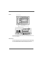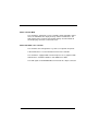
1
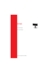
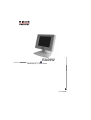
BA69W
LC-Display 5,7’‘ black/white
User Guide
BA69W
User Guide
Edition August 2004
PENTIUM® is a registered trademark of Intel Corporation
MS-DOS® is a registered trademark of the Microsoft Corporation
BEETLE® is a registered trademark of Wincor Nixdorf International GmbH
Copyright © Wincor Nixdorf International GmbH, 2004
The reproduction, transmission or use of this document or its contents is not permitted
without express authority.
Offenders will be liable for damages.
All rights, including rights created by patent grant or registration of a utility model or design, are
reserved.
Delivery subject to availability; technical modifications possible.
CONTENTS
Manufacturer´s Certification ...................................................................1
Important notes ..........................................................................................2
Warranty.....................................................................................................3
Introduction ..............................................................................................4
What does VGA/4 mean?...........................................................................5
About the manual .......................................................................................6
Cleaning the BA69W ..................................................................................6
Recycling the BA69W.................................................................................7
Before assembling ...................................................................................8
Unpacking and checking the packing list ...................................................8
Wiring connections for the BA69W ........................................................9
Data cable plug connection....................................................................10
Connection to the VGA/4 controller MUX ..............................................11
Connection to the VGA/4 embedded scale controller ............................11
Disconnecting the cable.........................................................................11
Assembly ................................................................................................12
Base stand ...............................................................................................12
Tube assembly .........................................................................................14
TA85 Keyboard ........................................................................................16
Adjustment options................................................................................17
Rotating and tilting....................................................................................17
Adjusting the contrast...............................................................................18
Controller ................................................................................................19
VGA/4 Controller MUX .............................................................................19
VGA/4 Embedded Scale Controller..........................................................20
Replacing/Cleaning the glass cover.....................................................21
Replacing the backlighting....................................................................25
Appendix .................................................................................................33
Technical data BA69W.............................................................................33
VGA/4 Controller MUX ...........................................................................34
VGA/4 Embedded Scale Controller .......................................................34
Hardware design ......................................................................................35
LCD Display ...........................................................................................36
Inverter...................................................................................................37
VGA/4 interface......................................................................................37
VGA/4 controller MUX............................................................................37
VGA/4 embedded scale controller .........................................................37
Abbrevations ............................................................................................38
Manufacturer´s Certification
The device complies with the requirements of the EEC
directive 891336/EEC with regard to ‘Electromagnetic
compatibilily".
Therefore, you will find the CE mark on the device or packaging.
GB - 1
Important notes
The display BA69W conforms to the current safety standards for data
processing equipment.
r If this device is taken from a cold environment into the operating
room, moisture condensation may form. The device must be absolutely dry before being put into service; an acclimatization period
of at least two hours must therefore be observed.
r This device is equipped with a safety-tested power cable and may
be connected only to a prescribed grounded-contact power socket.
r When setting up the device, ensure that the power socket on the
device and the grounded-contact power socket are easily accessible.
r To disconnect the device from the supply voltage completely,
switch off the POS System and disconnect the power plug.
r Ensure that no foreign objects (e.g. office clips) find their way into
the device, as this may lead to electric shocks or short-circuits.
r In order to ensure that the device is well ventilated and to prevent
overheating, do not obstruct the ventilation slots on your device.
r Never plug in or unplug data communication lines during thunderstorms.
r Protect devices from vibrations, dust, moisture and heat.
r In emergencies (e.g. damaged housing or damaged power cable,
penetration by liquids or foreign bodies), the device must be switched off immediately, the power plug disconnected and the Customer Service of Wincor Nixdorf International GmbH or your dealer
must be notified.
GB - 2
The device may only be repaired by authorized qualified
personnel. Unauthorized opening of the device and inexpertly carried-out repairs may not only seriously jeopardize the safety of the user, but also cancel all warranty
and liability agreements.
Warranty
Wincor Nixdorf (WN) guarantees a limited warranty engagement for 12
months beginning with the date of purchasing. This warranty engagement covers all those damages which occur despite a normal use of
the product.
Damages because of
- improper or insufficient maintenance,
- improper use of the product or unauthorized modifications of the
product,
- inadequate location or surroundings
will not be covered by the warranty.
For details please consult your contract documents.
All parts of the product which are subject to wear and tear are not included in the warranty engagement of Wincor Nixdorf. Please order
spare parts at the WN customer service.
GB - 3
Introduction
The BA69W liquid-crystal display is a tailor-made operator display for
modern cash-register applications with an embedded scale solution.
The BA69W has a 5.7" screen for black/white presentation and is designed with STN technology.
The flat screen provides standard VGA compatibility in the 1/4-format
of a standard screen. As a result, graphic user interfaces are presented with a high information content that is easily viewed for both customers and operators. Graphics capability and different fonts make the
configuration of the information which is presented a pleasure.
The display can be integrated into your cash-register system in different ways. You may select between the version with its own base
stand, a tube assembly, or assembly on the TA85 keyboard.
There are two buttons on the BA69W for tare and zero setting. These
buttons are necessary for the scale solution.
The BA69W is used as a combined POS and scale display.
There are two ways for connectin the display:
r VGA/4 controller MUX
To this controller you can connect a BA69W and a BA69 in parallel. In this case they are used as a customer display or a operator
display. This solution runs with MS-DOS operating system.
r VGA/4 embedded scale controller
Connect a BA69W to this controller as a combined POS and
scale display. This solution runs with Windows / Linux operating
systems.
GB - 4
What does VGA/4 mean?
VGA/4 means that 1/4 of a full screen is utilized for every display.
The illustration shows the arrangement of the VGA quadrants
(320x240 picture elements) for the operator and customer displays to
the standard for a VGA screen with a resolution of 640x480 picture elements.
640
1st Quadrant
2nd Quadrant
Customer Display
BA69
is not used
plug connector: LCD1
480
240
320
3rd Quadrant
240
Combined POS/scale
display BA69W
4th Quadrant
is not used
plug connector: LCD2
It should be noted here that, in comparison with a standard VGA
screen, the entire right half of the screen is not visible. As a result,
standard applications cannot be displayed at the BA69W.
You can only use software which has been appropriately adapted.
GB - 5
About the manual
References in the Manual are indicated by this symbol.
This symbol is used for cautions and warnings.
Cleaning the BA69W
During cleaning, be absolutely sure that the cash-register system is
shut off, that the power cable has been disconnected, and that no moisture is allowed into the interior of the display.
Clean your BA69W at regular intervals with a cleaner which is
suitable for plastic surfaces. This cleaner may be ordered from
Wincor Nixdorf-Plus.
Clean the protective glass with a commercially-available glass cleaner.
Clean the internal display module with a lint-free cotton cloth only.
For information on gaining access to the protective
glass, refer to the chapter on “Changing the protective
glass cover.”
GB - 6
Recycling the BA69W
Environmental protection
does not begin when it comes time to dispose of a device; it begins with the
manufacturer.
The LC-Display BA69W is
manufactured without the
use of CFCs und CCHS and
is produced mainly from reusable components and materials.
The processed plastics can, for the most part, be recycled. Even the
precious metals can be recovered, thus saving energy und costly raw
materials.
At this time, there are still some parts that are not reusable. Wincor
Nlxdorf guarantees the environmentally safe disposal of these parts in
a Recycling Center, which is certified pursuant to ISO 9001.
So don’t simply throw your BA69W an the scrap heap when it has served its time, but take advantage of the environmentally smart,
up-to-date recycling methods!
Our environmental protection section is always ready to answer any
questions you may have about our environmental protection policies.
Or visit us on the Internet: www.wincor-nixdorf.com
GB - 7
Before assembling
Unpacking and checking the packing list
Unpack the parts and check to be sure that the packing list agrees with
the specifications on the bill of delivery.
If you determine that there is shipping damage or discrepancies between the packing list and the bill of delivery, please inform your contract affiliate or the sales office of Wincor Nixdorf immediately.
We recommend that you keep the original packaging in
case it should be necessary to ship the equipment again
(protection from shock and impact).
GB - 8
Wiring connections for the BA69W
The installation of the system should be performed in the sequence given in the following description:
n
Be sure that the power plug of the cash-register system has been
disconnected.
n
Plug the data cable in the BA69W and the jack of the controller on
the cash-register system.
n
Plug in the power cable of the cash-register system into the socket
again.
Never plug in the data cable or power supply cable when
the system is switched on.
GB - 9
Data cable plug connection
Grasp the cable cover panel at the locations marked by the arrows.
Pull the cable cover panel downward and remove it to the rear.
Push the data cable into the BA69W display as shown in the illustration
until you hear an audible click as it engages. Then replace the cable
cover panel.
GB - 10
Connection to the VGA/4 controller MUX
Two liquid-crystal displays can be connected to the supplied controller.
The BA69W display is always connected at the LCD2 jack. Insert the
data cable into the corresponding jack until the plug connector engages audibly.
LCD
1
2
Connection to the VGA/4 embedded scale controller
The BA69W display is connected at the BA69W jack. Insert the data
cable into the corresponding jack until the plug connector engages audibly.
COM interface
Protection
seal
Scale interface
BA69W
Disconnecting the cable
Remove the cable cover panel (refer to the previous page). Never disconnect cables by pulling on the cable itself. To disconnect the cables,
press on the releases on the plug connector marked by the arrows and
pull the connector downward.
GB - 11
Assembly
Base stand
Insert the display in the base stand so that the groove (arrow) advances into the guide of the base stand and audibly engages.
GB - 12
Connect the plug connector on the rear of the BA69W and secure the
cable cover panel. Connect the data cable to the cash-register system.
GB - 13
Tube assembly
First thread the cable for the display through the two tubes as shown in
the illustration. There is a square recess in the short tube which is provided especially for the smaller plug connector of the BA69W. The plug
connector can easily be guided from below through this recess.
The lower tube depicted in the illustration is not a part of
the packing list for the BA69W. The tube must have an
outside diameter of 40 mm with a maximum wall thickness of 2 mm.
GB - 14
Before positioning the support bracket, check once again
to be sure that the smaller plug connector is
positioned at the top.
Then position the support bracket for the display on the short tube.
When doing this, the slot (1) must be located between the two clips (2
and 3). Press downward firmly on the support bracket until it engages.
2
3
1
Support bracket
Now insert the display so that the groove (arrow) moves into in the
guide of the support bracket and engages.
Secure the plug connector of the data cable as described in the chapter “Wire connections for the BA69W” (page 10).
GB - 15
TA85 Keyboard
First remove the cover on the keyboard. Insert a coin into the gap on
the rear of the cover and pry the cover loose.
Mount the display on the keyboard (refer to the illustration).
Secure the plug connectors of the data cable as described in the chapter “Wire connections for the BA69W”.
GB - 16
Adjustment options
Rotating and tilting
You can tilt the display up to 45 degrees to the rear and 10 degrees
forward. With the tube assembly, the display can also be rotated by up
to 330 degrees.
GB - 17
Adjusting the contrast
You will find the rotary knob for the contrast setting on the rear of the
display (refer to the enlarged section of the illustration).
GB - 18
Controller
VGA/4 Controller MUX
The controller is suitable for connecting a combined POS and scale
display. The BA69W display is always connected at the LCD2 jack.
This controller is used when the embedded scale controll has no
VGA/4 interface.
Below: Illustration of the controller mask panel.
LCD
1
2
The installation of the controller is described in the BEETLE documentation in the chapter on “Installation of an expansion card.”
Your cash-register system must have a free PCI slot.
Remove any VGA card which might be present.
GB - 19
VGA/4 Embedded Scale Controller
The BA69W display is connected at the BA69W jack. Insert the data
cable into the corresponding jack until the plug connector engages audibly.
Below is an illustration of the controller mask panel.
COM interface
Protection
seal
Scale interface
BA69W
Furthermore the controller panel provides
r a COM connector for the connection to the COM interface of the
BEETLE system
r a seal for securing the scale calibration switch and
r an interface for connection a scale unit.
GB - 20
Replacing/Cleaning the glass cover
If the protective glass cover is scratched or cracked, you should replace it. Also, proceed as follows if you wish to clean the cover from the
inside.
First switch the cash-register system off and disconnect
the power plug.
Then remove the cable cover panel on the display.
GB - 21
Disconnect the cable: To disconnect the cable, press on the releases
on the plug connector marked by the arrows and pull the connector
downwards.
Now press the two release tabs on the rear of the display downwards.
GB - 22
The display cover can now be rotated forward.
Release the glass cover by pulling the plastic section gently outward at
the location marked (1) while simultaneously pressing the glass cover
(2) out from the bottom.
1
2
In order to avoid fingerprints on the inside of the new
glass cover, grasp it only on the edges.
GB - 23
Avoid touching the display screen in the following steps.
Insert the new protective cover below the clip retainers shown in
the illustration (below) and then press it carefully past the opposite
alignment retainer.
Then position the display housing on the screen and close it until the
lower locking tabs audibly engage.
GB - 24
Replacing the backlighting
If the backlighting should malfunction, you can replace it with a few
easy steps.
First switch the cash-register system off and disconnect
the power plug.
Then remove the cable cover panel on the rear of the display.
A damaged backlighting is not covered by warranty
engagement.
GB - 25
Disconnect the cable. To disconnect the cable, press on the releases
on the plug connector marked by the arrows and pull the connector
downward.
Now press the two release tabs for the front section on the rear of the
display downward (refer to the illustration).
Avoid touching the display screen in the following steps.
If the screen should get dirty, use a lint-free cotton cloth
only to clean it.
GB - 26
The cover of the display can now be rotated forward.
Pull the entire display upward and out of the support bracket and place
it carefully on a smooth, clean and soft work surface with the screen
side facing downward.
When the front cover is removed, grasp the display only
on the rear plastic housing. If you do not do this, you
could damage the internal display.
GB - 27
Press the retainers on the rear panel and remove the panel toward the
top.
GB - 28
You will see the cable for the backlighting on the left side of the housing next to the inverter.
First lift the cable from the x-support bracket and then from the
y-support bracket so that the cable is freed.
Pull out the plug connector (1) for the backlighting on the inverter.
1
GB - 29
Now remove the cable from the channel. Then fold the three marked
tabs upward and remove the backlighting on the cable vertically upward.
GB - 30
Do not touch the new backlighting on the glass body.
Insert the new backlighting and lock it in place by folding the tabs back.
Position the cable in the cable channel (1) and around the cable retainer (2). Following that, plug the plug connector into the inverter (3) and
route the cable in front of the second cable retainer (4).
3
2
4
1
Reassemble the display in the opposite order.
GB - 31
Appendix
Technical data BA69W
Technology
STN (Super Twisted Nematic)
Type
1/4 VGA monochrome
Size
5,7"
Resolution
320 (H) x 240 (V) pixel
Visible area
120 (H) x 89 (V) mm
Pixel format
0,36 x 0,36 mm
Brightness
approx. 120 cd
Contrast
approx. 25
Supply voltage
12 V, via LCD cable
Mounting
Base, tube , keyboard
Mode:
VGA/4 controller MUX
VGA/4 embedded scale ctrl.
GB - 32
VGA Standard with 16 grey levels
VGA/4 mode black/white
with 1 pixel per bit
Climatic category
JEC 721-3-3- class 3K3
Current consumption
210 mA +12 V
Cable
Length: 2.50 m oder 1.50 m
20pol. twisted pair, EMC-shielded
Dimension
126 mm x 87 mm
VGA/4 Controller MUX
System interface
PCI
PCI-Frequency
max. 33 MHz
Bus
32 Bit
VGA Standard
Fully compatible
Connectors at bracket
1. 26pol MDR for LCD1 with
power supply 12 V
2. 26pol MDR für LCD2 iwith
power supply 12 V
5V @ 400 mA
Current consumption
VGA/4 Embedded Scale Controller
System interface
RS 232
Speed
960bd
Protocoll
dialog6 extended
Mode
VGA/4, b/w, 1 bit per pixel
Connectors at bracket
26pol MDR with power supply 12 V
for customer display
Current consumption
5V @ 350 mA
12 V @ 250 mA incl. scale
GB - 33
Hardware design
The block diagram shows the functions and the internal and external connections of the BA69W.
VGA/4 LCD-Modul
Inverter for CFL backlighting
VGA/4 interface
3
2
STN display 5,7"
320 x 240
LCD
interface
14
tare, zero setting
2
Contrast adjustment
20
LCD Display
Signals: STN-LCD, POWER SUPPLY P12V,
tare and zero setting
VGA/4 Controller MUX
LCD
1
0
2
1
100-120 V / 2 A max
200-240 V / 1 A max
DC24V
1
2
CASHDR ONLY
LPT1
B
A
MIC
KYBD
COM1
COM2*
USB
COM3*
COM4*
LAN
SPK
The 5.7-inch monochrome display with STN technology has a resolution of
320 x 240 picture elements.
GB - 34
Inverter
VGA/4 LCD-Modul
Inverter for CFL backlighting
VGA/4 interface
LCD
interface
3
2
STN display 5,7"
320 x 240
14
2
Tare, zero setting
Contrast adjustment
20
Signals: STN-LCD, POWER SUPPLY P12V,
Tare and zero setting
VGA/4 Embedded Scale Controller
0
1
100-120 V / 2 A max
200-240 V / 1 A max
DC24V
1
2
CASHDR ONLY
LPT1
B
A
MIC
KYBD
COM1
COM2*
USB
COM3*
COM4*
LAN
SPK
The inverter generates the high voltage of the LCD display which is necessary for the backlighting.
VGA/4 interface
The STN display and the inverter are linked via the internal VGA/4 interface. There is a potentiometer for contrast adjustment of the LCD. The interface is linked with the VGA/4 controller via a 20-pin plug connector.
GB - 35
VGA/4 controller MUX
The controller is configured as a PCI card with a VGA-compatible controller IC, the VGA-BIOS, the display memory, and the LCD interface. The
LCD signals for the customer and operator displays are transmitted via
two 26-pin plug connectors on the front mask.
VGA/4 embedded scale controller
The controller can be integrated to a system as an optional component.
A RS 232 interface is used for the data transfer of the controller.
The controller is equipped with a 16 bit microprocessor, a graphic IC with
LCD interface, a firmware PROM, a static RAM and a UART.
The LCD signals for the BA69W will be transferred via a 26-pin connector.
GB - 36
Abbrevations
CFL
Cold cathode Fluorescent Lamp
COM
Communication Port
cUL
canada Underwriters Laboratories
EPROM
Erasable Programmable Read Only Memory
GS
Tested safety
GUI
Graphic User Interface
ISO
International Standardization Organization
LCD
Liquid Crystal Display
MDR
Mini Delta Ribbon (connector family of 3M)
OTP
One Time programmable (EPROM type)
PCI
Peripheral Component Interconnect
QS
Quality safety
RAM
Random Access Memory
ROM
Read Only Memory
SIMM
Single-In-Line-Memory-Modul
SMT
Surface-Mount-Technology (assembly form)
SRAM
Static Random Access Memory
STN
Super Twisted Nematic (LCD Technology)
VGA
Video Graphics Array
UL
Underwriters Laboratories
GB - 37