1
BOXLIGHT PRO80S3 Projector Preliminary User’s Manual
BOXLIGHT PRO80S3 Projector
User’s Manual
For Controller Firmware Revision 0.73
and Motor Control Firmware Revision 2.0
7 July 2008
BOXLIGHT, Inc.
NE 151 Highway 300, Suite A
PO Box 2609
Belfair, WA 98528
For Controller Firmware Revision 4B/6.3 2007.0206
BOXLIGHT PRO80S3 Projector Preliminary User’s Manual
1.
Introduction
The Boxlight PRO80S3 Projector is a three-chip DLP projector with a native resolution of 1280x720 pixels (16:9 aspect
ratio). The projector accepts 720p video through a DVI-D connector on the rear panel.
1.1
Controllers
The projector is controlled by a pair of MTV312M64 microcomputers. The first is the main controller and is responsible for
lamp ballast and formatter initialization. It continuously monitors the state of the formatters, the ballast and the video input
primarily to prevent the lamp from extinguishing due to loss of video or unintentional resetting of the formatters due to
power fluctuations. Communication with the controller is through an RS-232 interface using a simple command/parameter
protocol. The second processor manages the IR remote control functions: lens shift, focus and zoom. It has no external
communications interface except the IR receiver.
1.2
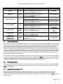
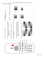
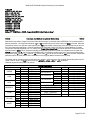
Rear Panel Connectors, Switches and Displays
There are four I/O connectors, two switches and nine LEDs on the rear panel.
Rear Panel Connectors, Switches and Displays
Connectors
Connector/Switch/LED
DVI-D
DB-9F
RJ-45
Switch
2-position Rocker Switch
3-position Rocker Switch
LEDs
RED/GREEN LED
8 GREEN LEDs
Purpose
720p Video Input. There is no scaler on board.
Serial Communications with main µC – 9600,8,N,1
Film Projector Lockout Connector
NIC
Located just about the power connector – System Power ON/OFF
Soft Power ON/OFF and Shutter Control
Power State – located to the left of the Power/Shutter Control Switch
Projector Status – Located to the left of the DVI Connector
Multicolor LED
Power Sequence State
Color
RED
GREEN
YELLOW
(GREEN + RED)
State
Standby
Power On or Power-up Sequence
IF some STATUS LEDs ON – 5 minute power-down
ELSE power-off sequence
Status LED Operation
STATUS LED
LAMP DOOR
FAN
LAMP
VIDEO SIGNAL
FORMATTER
BALLAST TEMP
READY
SHUTTER
When ON Continuously
Lamp Door Interlock OK
Lamp Thermal Switch Closed
Fans OK
Lamp Struck and Operating
Video Signal Detected
Formatters Initialized and Operating
Ballast Temperature OK
90 Second Lamp Cool-down Timer Expired, READY for
Power-up or Re-strike
Shutter OPEN
NORMAL Projection Mode
When Flashing (or OFF)
Lamp Door Open or
Lamp Thermal Switch Open - Shutdown
Fan Failure – Shutdown
Lamp Extinguished
Lamp Life time over system limited (1470 hours)
No Video
Formatter Failure (usually a communication failure) Shutdown
Ballast Temperature High – Shutdown
[READY OFF] 90 Second Lamp Cool-down Cycle in
Progress
Shutter CLOSED
CURTAIN mode
NOTE: There may be as much as a 2 second delay between an event that will cause a change in the STATUS LEDs, e.g.,
SHUTTER OPEN, and the actual display update.
Page 2 of 33
BOXLIGHT PRO80S3 Projector Preliminary User’s Manual
1.3
Power Sequencing
1.3.1
STANDBY
When the main power switch is turned ON, the projector comes up in STANDBY mode. It may be left in this state
indefinitely. Both controllers and the RS-232 circuitry are powered so that the unit can respond to serial commands, the IR
Remote Control or the rear panel switch. The ballasts, fans and formatters are not energized.
Note: The IR Remote POWER button is always active but the other buttons may be disabled. If the unit is powered up
using the IR Remote, all IR commands will be enabled. If the unit is powered up using the rear panel switch or via the
serial port, only the IR POWER button will be active. IR Remote buttons may be enabled or disabled with the IR+ and IRserial commands.
The projector may then be powered UP or DOWN using any of the methods above. The rear panel switch is
multifunctional. The following operation description assumes that the main power switch is ON:
If the projector is in STANDBY, the multicolor LED to the left of the switch will glow RED and on the 8 LED status display,
the READY LED will be ON. (If there were any problems encountered during the previous power-on cycle, other LEDs
may be flashing.) Depressing the left side of the switch momentarily (1/2 second or more) will power up the unit, turning on
the lamp and initializing the formatters. The multicolor LED will glow GREEN. The projector will come up in CURTAIN
projection mode with the shutter closed. The STATUS LEDs will display the progress of the power-up sequence. When all
of the LEDs except for the SHUTTER LED are lit, the shutter may be opened.
1.3.2
POWER ON
If the projector is POWERED UP, a momentary depression of the right side of the switch (1/2 second or more) will open
the SHUTTER and put the formatters in NORMAL PROJECTION MODE. Subsequent depressions will toggle between
NORMAL MODE/SHUTTER OPEN and CURTAIN MODE/SHUTTER CLOSED.
Depressing the left side of the rocker switch will cause the SHUTTER to close and the formatters to go to CURTAIN
MODE and also initiates a 5-MINUTE POWER DOWN cycle. During this time the lamp, fans and formatters remain active.
The multicolor LED will glow YELLOW (both the RED and GREEN are ON). The STATUS LEDs should all be ON except
for SHUTTER. If no other action is taken for the next 5 minutes, the projector will go through the 60 SECOND POWER
OFF sequence: the lamp is extinguished and the fans are left running for 60 seconds before going back to STANDBY. If
the shutdown was not due to some anomaly, e.g., a fan failure, all of the STATUS LEDs will be OFF. If there was an
anomaly, one or more may be flashing.
The READY LED will go OFF when the lamp is extinguished. It will go back ON after 90 seconds indicating that the lamp
may be re-struck. A command to re-strike via any of the three methods - serial, IR or switch – may be issued at any time
but the re-strike will not occur until the 90-second lamp cool-down has expired.
1.3.3
5 MINUTE POWER DOWN
If the projector is in the 5 MINUTE POWER DOWN sequence, a momentary depression of the left side of the switch (1/2
second or more) will initiate the 60 SECOND POWER OFF sequence. The 5 MINUTE POWER DOWN may be canceled
by issuing an ON or OPEN command through the serial port, by depressing the right side of the rocker switch or – if the IR
remote is enabled - depressing the BLANK button to open the SHUTTER. The multicolor LED will again glow GREEN.
1.3.4
60 SECOND POWER OFF
The 60 SECOND POWER OFF sequence first extinguishes the lamp, extinguishes the STATUS LEDs and resets the 90
second lamp cool-down timer. No re-strike will be permitted until it times out. If no further action is taken, after 60 seconds
the main power will be turned off – the fans go OFF - and the projector will be back in STANDBY.
Commands to restart the projector may be issued before the 60 SECOND POWER OFF sequence completes: serial ON
command, IR POWER button or left rocker switch. 60 SECOND POWER OFF will be canceled but the lamp will not restrike until the 90 second cool-down period has expired. The POWR STATE LED will show GREEN.
Page 3 of 33
BOXLIGHT PRO80S3 Projector Preliminary User’s Manual
Power and Shutter Operation
Current State
Power LED
STANDBY
RED
POWER ON
GREEN
5 MINUTE POWER DOWN
1.4
YELLOW
60 SECOND POWER OFF
YELLOW
SHUTTER CLOSED
GREEN or
YELLOW
SHUTTER OPEN
GREEN
POWER ON,
SHUTTER CLOSED,
FILM PROJECTOR
INTERLOCK ACTIVE
GREEN
Action
Serial Command – ON
Rocker Switch - depress Left Side ½ second or more
IR Remote - depress POWER 2 seconds or more
Serial Command – OFF
Rocker Switch - depress Left Side ½ second or more
IR Remote - depress POWER 2 seconds or more
Serial Command – ON or OPEN
Rocker Switch - depress Right Side ½ second or more (shutter OPEN)
IR Remote – depress BLANK (if IR enabled)
Serial Command – OFF
Rocker Switch - depress Left Side ½ second or more
IR Remote - depress POWER 2 seconds or more
Wait 60 seconds – no additional action required
Serial Command – ON
Rocker Switch - depress Left Side ½ second or more
IR Remote - depress POWER 2 seconds or more
Serial Command – OPEN
Rocker Switch - depress Right Side ½ second or more (shutter OPEN)
IR Remote - depress BLANK (if IR enabled)
Serial Command – CLOSE
Rocker Switch - depress Right Side ½ second or more (shutter OPEN)
IR Remote - depress FREEZE (if IR enabled)
Serial Command – no command available
Rocker Switch - depress Right Side 5 seconds or more to override Film
Projector Interlock
IR Remote - no command available
Resulting State
POWER ON
5 MINUTE POWER DOWN
POWER ON
Power Down Cancelled
60 SECOND POWER OFF
STANDBY
POWER ON
Lamp re-strike after 90 second
lamp cool-down
SHUTTER OPEN
Cancel 5 MINUTE POWER
DOWN
if in progress
SHUTTER CLOSED
SHUTTER OPEN
Override Film Projector
Lockout
Serial Communications
The controller UART must service communications from two sources: the RS-232 interface via the DB-9 connector on the
rear panel and the NIC interface. The NIC card controls a multiplexed that switches the UART between these two sources.
The controller firmware services three different command sets: one from the NIC card (which is not specified in this
document) and two from the RS-232 port. These two will be referred to as human and machine commands. The human
interface is a verbose natural language interface that is intended for manufacturing and maintenance operations via a PC
running a terminal program attached to the port. Incoming character are typically echoed back to the terminal and a variety
of status messages are routinely sent, especially during power-up up and down sequences and when system anomalies
are detected and corrected. The machine interface is a terse command set. Incoming characters are not echoed and no
data is sent to the host unless requested.
The controller’s UART is selectable at 9600 or 19200 baud, 8-bits, no parity and 1 stop bit. The receiver is interrupt driven
with a 64 byte queue. The transmitter is polled and has no queue. XON/XOFF (^Q/^S) flow control is implemented in both
directions. The DB9-F connector is wired as a standard PC computer peripheral and may be connected to a PC running
an ASCII terminal program with a straight-through serial extension cable – not a null-modem.
1.5
Film Projector Lockout
The film projector lockout feature uses an external signal control either turning the projector on/off or closing/opening the
shutter depending if the film projector lockout mode has been set to lock out or power control mode. See the command
FPOL for more details.
1.6
Enhanced Color Correction (P7)
Commands have been included to utilize Texas Instruments’ Enhanced Color Correction Algorithm. When viewing
REC709 images use Entertainment Experiences' film look target color gamut by selecting index 5. When viewing
Tristimulus images use Entertainment Experiences' XYZ target color gamut by selecting index 6. See the ECC command
for more details.
Page 4 of 33
BOXLIGHT PRO80S3 Projector Preliminary User’s Manual
1.7
Ambient Light Compensation
Commands have been included to utilize Texas Instruments’ Dgamma table selection. There are three Entertainment
Experience dgamma tables provided to compensate for low, medium and high ambient room light levels. For low light
levels use dgamma table 5. For medium light levels use dgamma table 9/10. For high light levels user dgamma table 14.
See the command GAMMA for more details.
1.8
Lamp Module Replacement
High pressure lamp may explode if improperly handled. Refer servicing to qualified service personnel. The customer
should never attempt to disassemble the lamp or to dispose of the lamp casing other than by returning to the dealer. If the
lamp breaks, leave the area immediately and stay away for at least 30 minutes and ventilate the room so as not to inhale
the mercury vapor. If you inhale the mercury vapor, see a physician immediately and follow their instructions. Lamp
replacement is recommended after 3000 hours of use. Wait 60 minutes after turning off and unplugging the projector
power cord before performing the lamp replacement.
Page 5 of 33
BOXLIGHT PRO80S3 Projector Preliminary User’s Manual
Page 6 of 33
BOXLIGHT PRO80S3 Projector Preliminary User’s Manual
Page 7 of 33
BOXLIGHT PRO80S3 Projector Preliminary User’s Manual
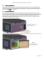
1.9
Filter Replacement
If the air filter is clogged with dust it can cause the projector to overheat , cause component failure or even catch on fire.
The filter should be replaced when clogged or when 10,000 hours of use has occurred. Contact the dealer to order a new
filter, never reuse an old filter. To replace the filter follow the steps that are provided in the following pages.
STEP 1: Remove the 2 screws.
Page 8 of 33
BOXLIGHT PRO80S3 Projector Preliminary User’s Manual
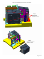
STEP 2: Lower the cover.
Page 9 of 33
BOXLIGHT PRO80S3 Projector Preliminary User’s Manual
STEP 3: Remove the filter.
STEP 4: Install the new filter, replace the filter cover and insert the 2 screws.
Page 10 of 33
BOXLIGHT PRO80S3 Projector Preliminary User’s Manual
1.10
Remote Control Key
Page 11 of 33
BOXLIGHT PRO80S3 Projector Preliminary User’s Manual
2.
Human Command Interface
The receive routine masks bit 7 of all characters received and buffers and echoes all printable ASCII characters. <TAB>s
are converted to <SPACE>s. Several other control characters are recognized or transmitted:
Name
Backspace
TAB
Line Feed
Carriage Return
DC1 – XON
DC3 – XOFF
Escape
Designation
<BKSP>
<TAB>
<LF>
<CR>
<CTRL-Q>
<CTRL-S>
<ESC>
HEX
0816
0916
0A16
0D16
1116
1316
1B16
Operation
Queue pointer decremented; echoed
Converted to <SPACE>
Placed in queue, not echoed, otherwise ignored
Placed in queue, not echoed, command terminator
Flow Control – Re-enable xmtr/rcvr
Flow Control – Disable xmtr/rcvr
Not placed in queue. Terminates current operations, flush queue
A number of control characters are set up as hot keys to perform the function of the Mode, Pattern, etc. buttons on the
PCB and on the rear panel switch via the serial interface. No <CR> terminator is required for these commands to execute.
See the first entry in Section 3.2 of the commands descriptions.
2.1
The ! Hot Key
Typing or sending a single exclamation point (!) immediately after the prompt with no whitespace or control characters –
will repeat the last command (the exclamation point is not echoed). If ANY characters are sent between the prompt and
the “!” – even a <CR> - the previous command will be lost and cannot be repeated using the “!” option. “!” just re-processes
the current contents of the command buffer so it will also repeat illegal commands or commands with illegal or missing
parameters.
2.2
ASCII Control Characters
In almost all cases sending an <ESC> character will terminate current operations and return a command prompt. It can
also be used when sending commands manually through a terminal to cancel any characters typed in after the prompt.
Whitespace characters - <TAB> and <SPACE> - are treated identically. Line feeds - <LF> - are queued but are otherwise
ignored by the code. A “newline” is always a <CR><LF> pair. The prompt is a newline followed by a > and a space.
Single <BKSP> characters are echoed and back up the queue pointer. A <BKSP> sent to the projector is not converted to
a “destructive” backspace string - <BKSP><SPACE><BKSP> when echoed. Only a single ASCII <BKSP> will be echoed.
If the terminal program can be configured to send <BKSP><SPACE><BKSP> when the Backspace Key is pressed, this
option should be selected.
Commands sent to the board in either mode can be terminated with either a single <CR> or a <CR><LF> pair. The <LF>
character triggers command parsing and execution. The <LF> is ignored. Neither commands nor hex data is casesensitive.
Page 12 of 33
BOXLIGHT PRO80S3 Projector Preliminary User’s Manual
2.3
ZOOM, FOCUS and Lens Shift Commands
ZOOM, FOCUS and Lens Shift Serial Commands
The following commands turn on the specified motors. The motors will stay energized until an <ESC> character is sent to
the projector. The last character of each command is an ASCII digit from 0 to 3 with no intervening whitespace. This
determines motor speed with 0 being the slowest and 3 the fastest. All of the motors have clutches or limit switches to
prevent damage if they are allowed to run after reaching a mechanical limit.
Command
Description
0≤ n≤ 3
Dn
Move image DOWN
Ln
Move image to the LEFT
FFn
Move FOCUS away from Projector – FOCUS FAR
FNn
Move FOCUS toward Projector – FOCUS NEAR
Rn
Move image to the RIGHT
Un
Move image UP
ZIn
ZOOM IN – Projected Image Smaller
ZOn
ZOOM OUT – Projected Image Larger
The following NUDGE commands turn on the specified motors for a short period. No <ESC> character need be sent. The
last character of each command is an ASCII digit from 0 to 3 with no intervening whitespace. This determines period the
motor is energized with 0 being the shortest and 3 the longest.
Command
Description
0≤ n≤ 3
NDn
Nudge image DOWN
NLn
Nudge image to the LEFT
NFFn
Nudge FOCUS away form Projector – FOCUS FAR
NFNn
Nudge FOCUS toward Projector – FOCUS NEAR
NRn
Nudge image to the RIGHT
Nun
Nudge image UP
NZIn
Nudge ZOOM IN – Nudge Projected Image Smaller
NZOn
Nudge ZOOM OUT – Nudge Projected Image Larger
Page 13 of 33
BOXLIGHT PRO80S3 Projector Preliminary User’s Manual
2.4
User Commands
Command
CLOSE
DGAMMA
FPOL
Gamma
GETP
IR+
IRLH
LAMPON1
LAMPON2
LAMPOFF1
LAMPOFF2
M+
MOFF
ON
ONS
OND
OPEN
P ID
SIZE
SETP
STS
V+
VVER
2.5
Enhanced Color Correction Commands
Command
ECC
MDNLD
RDMCGD
RDTCGD
TDNLD
∗1
User Serial Commands
Brief Description
Close Shutter and put Formatters in Curtain Mode
DGAMMA Dowlnoad
TOGGLE the Film Projector Lockout Polarity
Select Gamma Table
Get IR Remote
Enable IR Remote
Disable IR Remote except POWER Button (default at Power-up)
Display Lamp 1 or 2 Age Data
Turn On Lamp1*
Turn On Lamp2*
Turn Off Lamp1*
Turn Off Lamp2*
If V- enable display of non-critical (informational) messages – preceded by %
If V- disable display of non-critical (informational) messages – preceded by %
Main Power Shutdown
Main Power ON
Main Power ON and Start Signal Lamp mode∗
Main Power ON and Start Dual Lamp mode*
Open Shutter and put Formatters in Normal Projection Mode
Check Projector Serial Number
Set Display Size
Set Lamp Power Mode*
Check Shutter Status
Enable Verbose Mode
Disable Verbose Mode (see M+ and M- above also)
Display Controller Firmware Revision
DEBUG/Maintenance Serial Commands
Brief Description
Enable/Disable P7 Color Correction and Select Target Data
Download Measured Color Gamut Data for Storage in BLUE Formatter EEPROM
Display Measured Color Gamut Data
Display Specified Target Color Gamut Data
Downlaod User-Defined Target Color Gamut Data for Storage in EEPROM
: mark for MH-69 only.
Page 14 of 33
BOXLIGHT PRO80S3 Projector Preliminary User’s Manual
2.6
DEBUG/Maintenance Commands
Command
BAUD
FH
FR
FRB
FRG
FRR
FW
FWB
FWG
FWR
OCMD
RST
DEBUG/Maintenance Serial Commands
Brief Description
Change immediate and power-up baud clock
Display the FORMATTER Register Help Table
Read Register from ALL Formatters
Read BLUE Formatter Register
Read GREEN Formatter Register
Read RED Formatter Register
Write Register to ALL Formatters
Write to BLUE Formatter Register
Write to GREEN Formatter Register
Write to RED Formatter Register
Send Command to Ostram Ballast and Display Response
Reset and Reinitialize Formatters
Page 15 of 33
BOXLIGHT PRO80S3 Projector Preliminary User’s Manual
3.
Human Command Descriptions
3.1
Lens Shift, ZOOM and FOCUS Commands
The following commands turn on the specified motors. The motor will stay energized until an <ESC> character is sent to
the projector. The last character of each command is an ASCII digit form 0 to 3 with no intervening whitespace. This
determines motor speed with 0 being the slowest and 3 the fastest.
If an N prefix is appended to the command mnemonic the command is a NUDGE. NUDGE commands turn on the
specified motors at full speed for a timed period. An <ESC> character is not needed to terminate the command. The
purpose is to generate small changes in image position, focus or size. The last numeric character of the command
determines period the motor is energized with 0 being the shortest and 3 the longest. Due to backlash in the motor/drive
assemblies, a single NUDGE – especially a 0 or 1 – may not generate any noticeable change.
All of the motors have clutches or limit switches to prevent damage if they are allowed to run after reaching a mechanical
limit.
Un, Dn, Ln, Rn,
Nun, NDn, NLn, NRn
Lens Shift
Un, Dn, Ln, Rn,
Nun, NDn, NLn, NRn
UP, DOWN, LEFT and RIGHT. Move the projected image.
Example:
U3
NL1
FFn, FNn, NFFn, NFNn
FOCUS
FFn, FNn, NFFn, NFNn
FOCUS FAR and FOCUS NEAR. FOCUS FAR move the focus away from the projector while FOCUS NEAR moves it
toward the projector.
Example:
FN0
NFF3
ZIn, ZOn, NZIn, NZOn
ZOOM
ZIn, ZOn, NZIn, NZOn
ZOOM IN and ZOOM OUT. ZOOM IN makes the projected image smaller while ZOOM OUT makes it larger.
Example:
ZI2
NZ01
Page 16 of 33
BOXLIGHT PRO80S3 Projector Preliminary User’s Manual
3.2
User Commands
Control Characters
Several ASCII Control Characters are recognized to control Brightness, Contrast, Display Mode, Patterns and Orientation.
These are hot keys – i.e., no need to press ENTER.
<CTRL-Z>
Brightness – Decrement Lower Level
R/G/B Brightness=1D/1D/1D
<CTRL-X>
Brightness – Increment Lower Level
R/G/B Brightness=1C/1/C/1C
<CTRL-W>
Contrast – Decrement Upper Level
R/G/B Contrast=03/03/03
<CTRL-E>
Contrast – Increment Upper Level
R/G/B Contrast=02/02/02
<CTRL-N>
Cycles through the Projection modes
CURTAIN
<CTRL-O>
Cycles through the Projection orientations (FRONT, REAR, CEILING, etc.)
REAR-CEILING
<CTRL-P>
Cycles through the Patterns (when in PATTERN MODE)
PATTERN = 6
CLOSE, OPEN
SHUTTER Control
CLOSE, OPEN
OPEN opens the projector’s shutter and puts the formatters in NORMAL projection mode if:
a)
The power is ON AND
b)
The Film projector interlock is inactive
OPEN cancels a 5 MINUTE POWER DOWN sequence if it has been initiated.
CLOSE closes the projector’s shutter and puts the formatters in CURTAIN projection mode if the main power is ON, i.e.,
the fans are running.
Syntax: open
close
Page 17 of 33
BOXLIGHT PRO80S3 Projector Preliminary User’s Manual
DGAMMA
Download to De-gamma Mailbox
DGAMMA
Download de-gamma tables to the formatter’s degamma mailbox. DGAMMA takes three parameters. The first is a single
letter (r, g, b or a) specifying which formatter (or all of them) gets the table. The second is also a single letter (b or w)
specifying whether the table is formatted as bytes or words (16 bits). The last is a decimal parameter which specifies the
number of entries (1/2 the total number of bytes). Valid values for this parameter are 256, 512, 1024, or 2048. After the
command is issued, the user will be prompted to send the table as a series of hexadecimal bytes or words. Each entry is
16 bits. If byte mode is selected, send the LSB first. The table can be formatted rather loosely. Any ASCII character less
than ‘0’ (3016) is treated as a terminator. Any number of terminators may be inserted between values so the table can be
a single column of values separated by “newlines” or a column of comma separated values or even a string of hex digits
without any terminations as long as leading zeros are included with each byte or word.
If all formatters are to be loaded, a prompt will be issued after each successful download and a total of three separate
tables will have to be sent.
Syntax: dgamma {r|g|b|a} {b|w} {256,512,1024,2048}
> dgamma
Invalid De-Gamma Destination
> dgamma b 256
Data Size must be 'B' or 'W'
> dgamma b b 256
De-Gamma Download to BLUE FormatterXMIT EXACTLY 512 bytes of hexadecimal data
FPOL
Film Projector Interlock
FPOL
The film projector interlock feature operates in two modes: lockout mode and power control mode. FPOL takes either one
or no parameters.
In lockout mode the film projector interlock circuitry senses current in the External Interlock connector that is attached to
the Feature Film Projector. The lockout, when active, closes the shutter on the E-Cinema Projector and puts its formatters
in CURTAIN mode and prevents the shutter from being re-opened until the lockout becomes inactive. Depending on the
installation, the Feature Film Projector could be active or inactive when a voltage of about 5 volts is applied to the External
Interlock connector. FPOL sets or toggles the polarity of the sensing circuitry between active-when-energized [FPOL 0]
and active-when-not-energized [FPOL 1]. The unit is shipped with the polarity set to 0 [active-when-energized] so that if
the interlock is not connected, the projector will not be locked out. There is a way to override the lockout by depressing the
right side of the Power/Shutter rocker switch for more than 5 seconds.
In power control mode [FPOL 2], the polarity is nor selectable. When the External Interlock connector is energized – a
voltage of about 5 volts is applied – the projector will turn on and will remain on until the voltage is removed. The shutter
will automatically open at completion of the power-up sequence whether or not there is any active video.
If the projector is in power control mode, to take it out of this mode attach a terminal to the serial port and type:
fpol 0 [ set lockout active-when-energized] or
fpol 1 [ set lockout active-when-not-energized]
Typing fpol without a parameter will have no effect.
If the projector is in lockout mode:
fpol [ toggle lockout polarity: 0 Þ 1, 1 Þ 0] or
fpol 0 [ set lockout active-when-energized] or
fpol 1 [ set lockout active-when-not-energized] or
fpol 2 [ set power control mode]
The polarity parameter is stored in EEPROM and once established it is not necessary to set it again.
Page 18 of 33
BOXLIGHT PRO80S3 Projector Preliminary User’s Manual
NOTE: When the projector is in power control mode, the External Interlock has absolute control over the projector power.
It locks out the other power on/off methods – serial port commands (on and off), the rear panel rocker switch and the IR
remote. To control the power or enable the IR remote during setup or testing, a terminal must be connected to the serial
interface and serial commands (fpol, ir+, etc.) must be issued. The projector can be returned to power control mode
with fpol 2.
Syntax: fpol [0 | 1 | 2]
> fpol
FP Polarity = 1
>
Film Projector ON
IR= 08
> fpol
FP Polarity = 0
>
Film Projector OFF
> fpol 0
FP Polarity = 0
> fpol 1
FP Polarity = 1
>
Film Projector ON
> fpol 2
FP Polarity = 2
GAMMA
GAMMA Table Select
GAMMA
Select GAMMA Table. It will store to EEPROM, and when system boots up will reload the gamma setting.
Syntax: GAMMA {Table Num}
0 < num < n
>gamma 2
Set Gamma index = 2
Page 19 of 33
BOXLIGHT PRO80S3 Projector Preliminary User’s Manual
Index
0
1
2
3
4
5
6
7
8
9
10
11
12
13
14
SETP
GETP
Name
Graphic Enhanced
NTSC
NTSC Enhanced
PAL SECAM
PAL SECAM Enhanced
EE Ambient Light Compensation #1 –
for low light level
EE Ambient Light Compensation #2
EE Ambient Light Compensation #3
EE Ambient Light Compensation #4
EE Ambient Light Compensation #5 –
for medium light levels
EE Ambient Light Compensation #6 –
for medium light levels
EE Ambient Light Compensation #7
EE Ambient Light Compensation #8
EE Ambient Light Compensation #9
EE Ambient Light Compensation #10 –
for high light levels
LAMP POWER MODE
Owner
TI
TI
TI
TI
TI
EE
EE
EE
EE
EE
EE
EE
EE
EE
EE
SETP
GETP
OSRAM Lamp support change lamp Output power. The output wattage of the lampdriver can be adjusted by command.
SETP is used to setup the lamp output wattage. For now, user can adjust 2 mode, 250W or 300W. And if system is
working in dual lamp mode, then it is set for dual lamp. It can’t separately set lamp setting. GETP is used to read lamp
output wattage. It can separately read the lamp setting.
Syntax: SETP {Power Mode} 0:250W ; 1:300W
GETP {Lamp Num} 1:Lamp1 ; 2: Lamp2
> setp 0
Set Lamp1 250W!
Set Lamp2 250W!
> getp 1
Lamp1 = 250W
IR+, IR-
IR Remote Enable/Disable
IR+, IR-
Enable (IR+) or disable (IR-) the infrared remote control interface. The IR remote POWER button is always enabled. If the
projector is powered up using the IR remote, all other IR buttons are also enabled until an IR- command is issued or
POWER OFF.
Syntax: ir+
ir> ir+
IR Enable !!
> irIR Disable !!
Page 20 of 33
BOXLIGHT PRO80S3 Projector Preliminary User’s Manual
LAMPON1
LAMPON2
LAMPOFF1
LAMPOFF2
LAMP On/Off
LAMPON1
LAMPON2
LAMPOFF1
LAMPOFF2
Turn ON/OFF the lamp, when system is powered on. LAMPON1 is turn lamp 1 on; LAMPOFF1 is turn lamp1 off.
LAMPON2 is turn lamp 2 on; LAMPOFF2 is turn lamp2 off. In dual-lamp mode, user turn off one lamp, the system will
switch to single lamp mode, and store the mode to EEPROM.
Syntax: LAMPON1
LAMPOFF1
LAMPON2
LAMPOFF2
> lampoff1
LAMP1 OFF !
> lampoff2
LAMP2 OFF !
> lampon1
LAMP1 ON !
> lampon2
LAMP2 ON !
M+, M-
Informational Message Reporting Control
M+, M-
Syntax: m+
m> m+
Monitor Info. On !!
> mMonitor Info. Off !!
ON, OFF, ONS, OND
POWER Control
ON, OFF, ONS, OND
Power sequencing commands. See section 1.3 for more details.
Command
ON
ONS
OND
OFF
ON and OFF Power Sequencing Commands
Current State
Resulting State
STANDBY [RED]
POWER ON
POWER ON [GREEN]
NO CHANGE
5 MINUTE POWER DOWN [YELLOW]
POWER ON – Power Down Cancelled
60 SECOND POWER OFF [YELLOW]
POWER ON – Lamp re-strike after 90 second
lamp cool-down
STANDBY [RED]
NO CHANGE
POWER ON [GREEN]
5 MINUTE POWER DOWN – Shutter closed
5 MINUTE POWER DOWN [YELLOW]
60 SECOND POWER OFF – Lamp OFF,
Shutter closed
60 SECOND POWER OFF [YELLOW]
NO CHANGE
Page 21 of 33
BOXLIGHT PRO80S3 Projector Preliminary User’s Manual
System boot up will reload the settings, as below:
a.
b.
c.
d.
e.
f.
Gamma setting
P7 setting
MCGD & TCGD
Lamp mode
Brightness & Contrast
Image Orientation
Syntax: ON
OFF
ONS
OND
→
→
→
→
Main Power On and Turn On lamp which last power off select lamp mode. If lamp mode is Single
lamp mode, then turn on the lamp which lifetime is small, then the other one.
Main Power Off.
Main Power On and Turn On Single lamp mode which lifetime is small, then the other one.
Main Power On and Turn On Dual lamp.
> on
Power On – Dual_Lamp
Lamp1 S/N = feng1
Lamp1 Time = 9:21
Lamp1 Strikes = 45
Lamp1 is Off !
Lamp2 S/N = feng2
Lamp2 Time = 9:43
Lamp2 Strikes = 74
Lamp2 is Off !
>
Powering Up
> ond
Power On -Dual_Lamp
Lamp1 S/N = feng1
Lamp1 Time = 3:15
Lamp1 Strikes = 35
Lamp1 is Off !
Lamp2 S/N = feng2
Lamp2 Time = 3:37
Lamp2 Strikes = 64
Lamp2 is Off !
>
Powering Up
> ons
Power On -Signal_Lamp Lamp 1
Lamp1 S/N = feng1
Lamp1 Time = 9:23
Lamp1 Strikes = 46
Lamp1 is Off !
Lamp2 S/N = feng2
Lamp2 Time = 9:45
Lamp2 Strikes = 75
Lamp2 is Off !
>
Powering Up
Page 22 of 33
BOXLIGHT PRO80S3 Projector Preliminary User’s Manual
P_ID
Show Projector ID
P_ID
Display Size
SIZE
Read Projector ID.
Syntax: p_id
> p_id
Projector Serial Number=123456
SIZE
Native image size on the HD2+ engine is 1280 x 720. Parameters are entered in decimal.
Syntax: size {HSIZE} {VSIZE}
- 640 ≤ HSIZE ≤ 1280, 480 ≤ VSIZE ≤ 720
> size 1280 720
Size: 1280X720
STS
Display Shutter Status
STS
VERBOSE Mode Control
V+, V-
Display Shutter Status.
Syntax: STS
> STS
Shutter is On !
V+, V-
Enable (V+) or disable (V-) VERBOSE mode on the serial interface. When VERBOSE is enabled all messages –
informational, error and status, etc. – are sent as human readable text. When disabled those messages are sent as a 6
character ASCII group. There are two types of messages: critical and non-critical. Non-critical messages can be enabled
or disabled using the M+ and M- commands. The first character of non-critical messages is a percent sign (%). Critical
messages are headed by an exclamation point (!). The next two characters form a unique 8-bit hexadecimal code
identifying the message (see below). The last three characters are a dollar sign ($) followed by a <CR> and <LF>.
DGAMMA and most of the DEBUG/Maintenance commands output verbose messages regardless of whether VERBOSE
is enabled or disabled.
Page 23 of 33
BOXLIGHT PRO80S3 Projector Preliminary User’s Manual
%01$
%02$
%03$
%04$
%05$
%06$
%07$
%08$
%09$
%0A$
!80$
!81$
!82$
!83$
!84$
!85$
!86$
!87$
!88$
!89$
!8A$
!8B$
!8C$
!8D$
!8E$
!8F$
!90$
!91$
!92$
!A0$
!E0$
!E1$
!E2$
!F0$
!F1$
!F2$
!F3$
!F4$
!F5$
!F6$
Non-Verbose Message Codes
Non-critical (Informational) Messages [M+ and V-]
LAMP Door Closed and Lamp TEMP OK
FANS OK
Film Projector ON – During Power-up
Film Projector OFF – During Power-up
Video Signal Detected – During Power-up
Striking Lamp – During Power-up
Restrike – Ballast RESET
Restrike – Lamp Restrike
Restrike – Restrike Fail
Ballast COMM Failure – typically non-critical unless it least to !88$
Critical Messages / Shutdown Messages [V-]
Lamp Door Open or Lamp Overtemp – if after Power-up ► Shutdown
FAN Problem – if after Power-up ► Shutdown
NO Video – during or after Power-up
Video Signal Detected - Video Restored
Lamp Lit - During Power-up
Formatter COMM Disabled - Check SW500 – Power-up sequence halted
Restrike - Lamp Lit - After Power-up - 30 second Warm up before Shutter OPEN
Restrike Count Exceeded ► Shutdown
Ballast not Responding - After Power-up ► try Restrike
Ballast OVERTEMP ► Shutdown
Lamp Extinguished - After Power-up ► try Restrike
Resetting Formatters – usually non-critical
LAMP SYNC Signal Inactive – usually non-critical
LAMP SYNC Detected – usually non-critical
Film Projector ON - After Power-up – Shutter CLOSED
Film Projector OFF - After Power-up
RED FORMATTER Status Read Error – usually non-critical
GREEN FORMATTER Status Read Error – usually non-critical
BLUE FORMATTER Status Read Error – usually non-critical
Power-up Sequence Complete – Ready for shutter OPEN
Invalid Parameter in Command line
Missing Parameter(s) in Command line
Unknown Command
Lamp Time Read from EEPROM – Lamp Hour EEPROM Read Error
Strike Count Read from EEPROM – Lamp Hour EEPROM Read Error
Power Off – MAIN Power OFF – System in Standby Mode
5 Minute Power Down Can celled by OPEN or ON Command
5 Minute Power Down Initiated – Lamp OFF and 60 second cool down in 5 minutes
Powering Up – Main Power ON - Initiating Power-up Sequence
Powering Down – Lamp OFF – 60 second cool down
Syntax: v+
v-
VER
VERSION
VER
Display Controller Firmware Revision:
ver
* 720p MHF-69 Monitor – Rev. D03J
*
17 Nov 2006
*Syntax:
ver
Page 24 of 33
BOXLIGHT PRO80S3 Projector Preliminary User’s Manual
3.3
Enhanced Color Correction (P7) Commands
ECC
Select P7 TARGET DATA
ECC
Select the Target Color Data. This command takes a parameter – the target index – between 0 and 13. The following table
lists the GRBW CIE color coordinates for the selected ECC index. Note that indicates 1 through 9 do not specify the
Magenta, Cyan or Yellow CIE values. Indices 10 through 13 specify user-definable tables which may include the CMY
coordinates as well as GAIN values for each of the colors and WHITE. See TI document – Product Specification for
DDP1000, DDP1010, DDP1011 Based Modular Formatter Component Set [Dwg #2503986, Rev. J or later] for details.
Index
Description
0
OFF
1
2
GREEN
X
BLUE
WHITE
X
Y
ANSI - 3200°K
.423
.399
ANSI - 5400°K
.335
.349
.210
Y
Target Color Gamut Data
RED
X
Y
X
ECC OFF
.710
.670
.330
.140
Y
.080
3
ANSI - 6500°K
.313
.329
4
ANSI - 9300°K
.283
.297
5
6
7
EE-REC709
EE-XYZ
User 2
8
User 3
9
Native
N/A
N/A
User Selectable GREEN, RED, BLUE, MAGENTA, CYAN,
YELLOW and WHITE CIE Indices stored in EEPROM
(See TDNLD)
.651
.655
.341
.147
.044
.296
.337
.316
Syntax: ecc {target index}
> ecc2
EC Set Index 2
ECC Enable
Freeze Frame On
Freeze Frame Off
MDNLD
Download Measured Color Gamut Data
MDNLD
Download Measured Color data for storage on the BLUE Formatter’s EEPROM. When the command is entered, the
operator is prompted to send 16 bytes of data: the X and Y CIE coordinates of the un-enhanced GREEN, RED, BLUE and
WHITE colors. Each coordinate is 16 bits - 2 bytes - sent least significant byte first in hexadecimal. For each coordinate,
first multiply by 65536 and convert to hexadecimal. Output two hexadecimal bytes, LS byte first, for each of the 8
coordinates in order: Gx, Gy, Rx, Ry, Bx, By, Wx, Wy , Bx By ,WY and BY. The values can be manually typed from the
terminal or stored in a file and sent to the controller board using the terminal’s “Send Text File” utility. Characters typed of
sent will NOT be echoed. The 16 bytes sent may be <SPACE>, <TAB>, <CR> or <LF> separated.
After the data is downloaded, the coordinates will be displayed in decimal format for confirmation.
Page 25 of 33
BOXLIGHT PRO80S3 Projector Preliminary User’s Manual
Syntax: mdnld
> mdnld
Enter Gx,Gy,Rx,Ry,Bx,By,Wx,Wy,Bx,By,WB,BB(x100) 12 datas:
.323,.649,.664,.334,.146,.041,.291,.307,.310,.000,3000,123
GREEN = .323,.649
RED = .664,.334
BLUE = .146,.041
WHITE = .291,.307
BLACK = .310,.037
CONTRAST= 2439
RDMCGD
Display Measured Color Gamut
Data in Use
RDMCGD
Display the Measured Color Gamut Data that is currently in use. If the calibrated data in the EEPROM on the BLUE
Formatter has not been loaded or has been corrupted, a default table is loaded.
Syntax: rdmcgd
> rdmcgd
GREEN = .340,.650
RED = .640,.350
BLUE = .140,.033
WHITE = .290,.330
RDTCGD
Display Target Color Gamut Data
RDTCGD
Display the Target Color Gamut Data for the specified index. This command takes a parameter – the target index –
between 1 and 9.
Syntax: rdtcgd {1 ≤ target index ≤ 9}
For indices 1 through 4 (in this example index 4) the following will be output to the terminal:
> rdtcgd 4
GREEN = .210,.710
RED = .670,.330
BLUE = .140,.080
WHITE = .423,.399
TOLBOX = .010
For indices 5 through 8 (in this example index 8) the full contents of the used-definable table will be displayed. The third
value for each color is the GAIN. See TI document – Product Specification for DDP1000, DDP1010, DDP1011 Based
Modular Formatter Component Set [Dwg #2503986, Rev. J or later] for details on the tolerance box specification and the
Copyright notice.
Page 26 of 33
BOXLIGHT PRO80S3 Projector Preliminary User’s Manual
> rdtcgd 8
GREEN = .337,.642,.000
RED = .642,.353,.000
BLUE = .140,.034,.000
MAGENTA = .000,.000,.000
CYAN = .000,.000,.000
YELLOW = .000,.000,.000
WHITE = .287,.326,.000
TOLBOX0 = .277,.336
TOLBOX1 = .297,.336
TOLBOX2 = .297,.316
TOLBOX3 = .277,.316
Use TOL BOX
Notice: 'P7 TCGD Data - 6300K - Copyright (c) 2006 Delta Products Corp.'
TDNLD
Download User-Defined Target Color Gamut Data
TDNLD
Download a User-definer Target Color Gamut Data Set for storage in controller board’s EEPROM. The command takes a
decimal parameter – the target index between 10 and 13 corresponding to the index used in the ECC command. When the
command is entered, the operator is prompted to send 140 bytes of data. A description of the data packet can be found in
the Texas Instruments document – Product Specification for DDP1000, DDP1010, DDP1011 Based Modular Formatter
Component Set [Dwg #2503986, Rev. J or later] in the Target Color Gamut Data command description. Note that the first
byte listed here is 8816. This is used when actually communicating with the Formatters and should not be sent with the
TDNLD command. Byte 2 – the LS Byte of the GREEN CIE X coordinate is the first value sent. The command description
only defines bytes 2 through 140 – a total of 139. Add an extra 0 byte to the end so that full 140 bytes are sent. Unspecified
parameters such as GAIN values, CMY coordinates or the Copyright Notice should be sent as zeros.
The values can be manually typed from the terminal or stored in a file and sent to the controller board using the terminal’s
“Send Text File” utility. The 140 bytes sent may be <SPACE>, <TAB>, <CR> or <LF> separated.
Characters typed of sent will NOT be echoed.
Field Contents
X
GREEN
Y
GAIN
X
RED
Y
GAIN
X
BLUE
Y
GAIN
X
MAGENTA
Y
GAIN
X
CYAN
Y
GAIN
X
YELLOW
Y
GAIN
X
WHITE
Y
GAIN
BYTES
2
2
2
2
2
2
2
2
2
2
2
2
2
2
2
2
2
2
2
2
2
Positions
Bytes 1-2
Bytes 3-4
Bytes 5-6
Bytes 7-8
Bytes 9-10
Bytes 11-12
Bytes 13-14
Bytes 15-16
Bytes 17-18
Bytes 19-20
Bytes 21-22
Bytes 23-24
Bytes 25-26
Bytes 27-28
Bytes 29-30
Bytes 31-32
Bytes 33-34
Bytes 35-36
Bytes 37-38
Bytes 39-40
Bytes 41-42
TDNLD Data Format
Field Contents
RESERVED – 00H
X
W TOL BOX 1
Y
X
W TOL BOX 2
Y
X
W TOL BOX 3
Y
X
W TOL BOX 4
Y
RESERVED – 00H
TOL BOX MODE
RESERVED – 00H
Copyright Notice –
ASCII – 0 PADDED
RESERVED – 00H
BYTES
6
2
2
2
2
2
2
2
2
6
1
1
Positions
Bytes 43-48
Bytes 49-50
Bytes 51-52
Bytes 53-54
Bytes 55-56
Bytes 57-58
Bytes 59-60
Bytes 61-62
Bytes 63-64
Bytes 65-70
Byte 71
Byte 72
64
Bytes 73-136
4
Bytes 137-140
Page 27 of 33
BOXLIGHT PRO80S3 Projector Preliminary User’s Manual
Syntax: tdnld {5 ≤ target index ≤ 8}
> tdnld 5
XMIT EXACTLY 140 bytes of hexadecimal data
Download TCGD 5
down !!
GREEN = .265,.690,.513
RED = .665,.312,.150
BLUE = .140,.070,.078
MAGENTA = .373,.178,.270
CYAN = .176,.337,.659
YELLOW = .457,.522,.916
WHITE = .314,.351,.:00
TOLBOX0 = .309,.355
TOLBOX1 = .318,.362
TOLBOX2 = .319,.347
TOLBOX3 = .311,.341
Use TOL BOX
Notice: 'c)Copyright 2002 Texas Instruments Inc.'
>
>
>
3.4
DEBUG/Maintenance Commands
BAUD
Switch BAUD Clock
BAUD
Immediate BAUD clock change. Only two rates are supported – 9600 and 19200. The clock rate on the terminal
programmed will have to be changed to continue. This command also sets the BAUD clock that will be set at start-up.
Syntax: baud {9600 | 19200}
FH
FORMATTER Register Help
FH
This command prints the register numbers, R/W status and name of the accessible DDP1011 formatter registers:
Syntax: fh
> fh
00 RW Brightness
01 RW Contrast
02 RW Projection Mode
03 RW Image Orientation
04 RW Mirror Park
05 RW Image Freeze
06 RW Vertical Frequency
07 RW Vertical Frequency Offset
08 RW Color Temperature Gain
09 RW Input Image Size
0A RW Image Position
0B RW Test Pattern Select
0C RW Formatter Input Data Type
0F RW 3D Sequence Set Select
10 RW Pulsed Lamp Data
11 RW Pulsed Lamp Ballast Sel
31 RW Color Space Matrix Select
32 WO Color Space Matrix Dnld
Page 28 of 33
BOXLIGHT PRO80S3 Projector Preliminary User’s Manual
33 RO Color Space Matrix Read
34 RW De-Gamma Table Select
35 RW De-Gamma Dnld Dest
36 WO De-Gamma Dnld Mailbox
40 RO System Configuration
41 RW DMD Bin Voltage Method Sel
42 RW DMD Bin Voltage Level Sel
43 RW Convergence
44 RW Formatter Color
45 RW Processing Path Select
46 RW Sequence Set Select
47 RO Sequence Sets Available
48 RO Sequence Set Data
49 RW Select LAMPSYNC Output
4A RW Flash MEM Access Time Sel
4C RW Command Sync ENABLE
50 RO System Status
51 WO System RESET
53 RO VERSION
55 RO Special Feature STATUS
60 WO Target Color Gamut Data
61 WO Measured Color Gamut Data
63 RW Enhanced Color Corr. Disable
FR, FRR,
FRG, FRB
FORMATTER Register Read
FR, FRR,
FRG, FRB
Read formatter registers:
FR
FRR
FRG
FRB
- Read all formatters
- Read RED formatter
- Read GREEN formatter
- Read BLUE formatter
The required parameter is the hexadecimal register number. The output is formatted as a stream of 8-bit or 16-bit
hexadecimal values as specified in the TI document – Product Specification for DDP1000, DDP1010, DDP1011 Based
Modular Formatter Component Set [Dwg #2503986, Rev. J]. See FW below.
Syntax: fr[r|g|b] {register number}
> fr 0
RED Formatter Brightness Register: 1500 1500 1500
GREEN Formatter Brightness Register: 1500 1500 1500
BLUE Formatter Brightness Register: 1500 1500 1500
> frr 0
RED Formatter Brightness Register: 1500 1500 1500
> frg 0
GREEN Formatter Brightness Register: 1500 1500 1500
> frb 0
BLUE Formatter Brightness Register: 1500 1500 1500
Page 29 of 33
BOXLIGHT PRO80S3 Projector Preliminary User’s Manual
FW, FWR
FWG, FWB
FORMATTER Register Write
FW, FWR,
FWG, FWB
Write formatter registers:
FW
FWR
FWG
FWB
- Write all formatters
- Write RED formatter
- Write GREEN formatter
- Write BLUE formatter
The first parameter is the hexadecimal register number. One or more additional parameters are required – the data to be
written. See the TI document – Product Specification for DDP1000, DDP1010, DDP1011 Based Modular Formatter
Component Set [Dwg #2503986, Rev. J] – for details. The first byte in the spec – Number of bytes being sent – and the
Protocol Pad bytes are not entered in the parameter list. As an example, the Brightness Register (0016) lists the following
data:
Byte
1
2
3
4
5
6
7
8
Description
Number of data bytes being sent (06h)
Green (lsb)
Green (msb)
Red (lsb)
Red (msb)
Blue (lsb)
Blue (msb)
Protocol Pad
Thus three words are required. To write the following data to the BLUE formatter BRIGHTNESS register:
Green = 148416 , Red = 18E016 and Blue = 0AF916
type:
fwb 0 1484 18e0 af9
To write to all Test Pattern Select register (0B16):
Byte
1
2
3
4
5
6
7
8
Description
Number of data bytes being sent (03h)
Test Pattern Number
Vertical Frequency Value (lsb)
Vertical Frequency Value (msb)
Protocol Pad
Protocol Pad
Protocol Pad
Protocol Pad
with Test Pattern select = 0616 and Vertical Frequency Value = 177116
type: fw b 6 1771
Syntax: fw[r|g|b] {register number} {data1 [data2]…[datan]}
To write the Brightness or Contrast in R/G/B channel,please follow the below command.
R/G/B Brightness:
Fw {Brightness} {Green-Brightness}{Red-Brightness}{Blue-Brightness}
>fw 0 7000 8000 9000
RED Formatter Brightness Register : 7000 8000 9000
GREEN Formatter Brightness Register : 7000 8000 9000
BLUE Formatter Brightness Register : 7000 8000 9000
Page 30 of 33
BOXLIGHT PRO80S3 Projector Preliminary User’s Manual
R/G/B Contrast:
Fw {Contrast} {Green-Contrast}{Red-Contrast}{Blue-Contrast}
>fw 0 8000 9000 7000
RED Formatter Contrast Register : 7000 8000 9000
GREEN Formatter Contrast Register : 7000 8000 9000
BLUE Formatter Contrast Register : 7000 8000 9000
OCMD
Ballast Communications
OCMD
This command is used for sending commands to the Osram Lamp ballast. The first parameter determines which of the two
ballast ports is addressed. The second is the ballast register address (hexadecimal – e.g., STATUS = 2216). See the
Osram documentation for register details. If the command requires data to sent those bytes are appended to the
command (hexadecimal and space delimited). If the command causes the ballast to return data – no just echo the
command – the response will be output in hexadecimal bytes. The ballast status command is special in that the status bits
are decoded (see below). Examples:
Syntax: ocmd { 1 | 2 } {ballast command} [data1] [data2] … [datan]
> ocmd 2 22
Command response = E0
LAMP BALLAST 2 STATUS BYTE:
RUN UP IN PROGRESS
MAX IGN TIME EXCEEDED
LAMP BURNING
> ocmd 2 3e
Command has no response.
> ocmd 2 60 96
Command response = 9D
> ocmd 2 60 98
Command response = D9
RST
Reset and Re-initialize the Formatters
RST
Perform hardware RESET of the 3 formatters and re-initialize them:
Syntax: rst
> rst
Reset Formatter Board Now !!
MCGD OK to Read
ECC Index 2
ECC Enable
Freeze Frame On
Freeze Frame Off
Reload Gamma Index = 1
Page 31 of 33
BOXLIGHT PRO80S3 Projector Preliminary User’s Manual
4.
Infrared Remote Control Interface
An IR interface is included for Lens Positioning, Zoom and Focusing adjustments. The IR remote control that is handled by
the firmware is Model T320L by Umate Corp., Taipai, Taiwan. It emits the following RECS80 codes:
Button
Code Assuming
LSB First
POWER
Mouse Knob
L Mouse Button
R Mouse Button
UP Arrow
DOWN Arrow
RIGHT Arrow
LEFT Arrow
ENTER
Keystone UP
Keystone DOWN
Volume UP
Volume DOWN
MENU
STATUS
MUTE
AUTO
SOURCE
ZOOM+
ZOOMBLANK
FREEZE
8C73817E16
N/A
N/A
N/A
8C73837C16
8C7343BC16
8C7323DC16
8C73C33C16
8C73A35C16
8C73A15E16
8C7321DE16
8C7331CE16
8C73F10E16
8C73E11E16
8C7311EE16
8C73916E16
8C73619E16
8C73C13E16
8C7385AE16
8C73B14E16
8C738D2E16
8C73718E16
Operation/Action
Toggle Main Power
Not decoded
Not decoded
Not decoded
Pan UP
Pan DOWN
Pan RIGHT
Pan LEFT
Reserved
Brightness/Contrast – Increment Lower Level
Brightness/Contrast – Decrement Lower Level
Brightness/Contrast – Increment Upper Level
Brightness/Contrast – Decrement Upper Level
Change Mode – same as <CTRL-N>
Change Pattern – same as <CTRL-P>
Change Orientation – same as <CTRL-O>
Focus FAR
Focus NEAR
ZOOM OUT – Image larger
ZOOM IN – Image smaller
Open Shutter – same as OPEN
Close Shutter – same as CLOSE
Control buttons other than those listed in BOLD above generate no activity.
4.1
Pan, Zoom and Focus Speed and Nudge Functions
The Pan, Zoom and Focus buttons can be used to manually control the projected image. All of the motors may be driven
at one of four speeds to make small incremental adjustments. In addition a nudge function is implemented. When any of
the control keys are pressed and released, the associated motors will be turned on for a short period of time, causing a
small incremental change in the image. In the following descriptions this nomenclature is used:
P
H
PP
..PH
= a quick button press and release – press and release time each less that about 0.25 seconds
= the button is held down
= two quick button presses and releases – down times and intervening up times each less that about 0.25
seconds, etc.
= One or more quick button presses and releases followed by a hold
The nudge function generates small changes in lens position,etc., by applying power to the associated motor for one of
four time intervals: 12.5, 25, 50 or 100 milliseconds. Nudges are generated by a number of quick button depressions and
releases. Nudge increments are controlled by the number of quick button presses – up to four. More than four are treated
the same as four.
P
PP
PPP
PPPP
PP..PP
– smallest change – 12.5 msec
– 25 msec
– 50 msec
– largest change – 100 msec
– largest change – 100 msec
Page 32 of 33
BOXLIGHT PRO80S3 Projector Preliminary User’s Manual
Continuous changes are generated by a number of quick presses followed by a hold. Motor speeds are determined by the
number of quick button presses – up to three – before holding the button down.
H
PH
PPH
PPPH
PP..PH
– very slow
– slow
– medium
– fast
– fast
Release the button to stop the motor. Note that there is about a 0.25 to 0.35 second delay between button release and
motor off.
Page 33 of 33