1
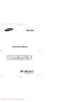
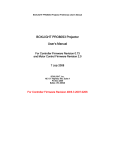
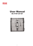
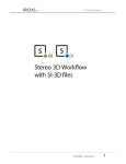
SERVICE BULLETIN DLP PRODUCT: BULLETIN NUMBER: ASC20050812002 BULLETIN DATE: 08/12/2005 HLPxx63 Series MODELS: HLPxx67 Series HLRxx66 Series HLRxx67 Series HLRxx77 Series Atlantis, Robocop, Chassis: Hurricane SUBJECT: Necessary Service Mode adjustments after replacing the Digital PCB. SYMPTOM: Distorted colors in the picture after replacing the Digital PCB. See figure 1. REPAIR: For all the models listed on this service bulletin the following Adjustments are required after replacing the Digital PCB: 1. INDEX DELAY 2. CCA 3. ACTUATOR GAIN Figure 1 If these parameters are not properly adjusted video issues such as distorted color will be visible on the screen. Follow the three procedures below depending on the situation to complete the adjustments properly after changing the Digital PCB. This information is published for experienced repair technicians only and is not intended for use by the public. It does not contain warnings to advise non-technical individuals of possible dangers in attempting to service a product. Only experienced professional technicians should repair products powered by electricity. Any attempt to service or repair the product or products dealt with in this information by anyone else could result in serious injury or death. Information provided in this bulletin is subject to change or update without notice. PROCEDURE 1: 1. If the DLP still has the ability to power on, then enter the Service Mode and record the data values from the original PCB. If this is not possible, skip to procedure 2. From stand-by mode enter the button sequence (MUTE + 1 + 8 + 2 + POWER) on the remote control. The DLP will turn on in Service Mode. From the main menu screen enter the DDP1011 menu. Record the INDEX DELAY value on the sub menu screen. Press MENU to return to the main menu screen. From the main menu screen scroll down and select the CCA menu. Enter the CCA menu and record the Red, Green, Blue and White (x, y & Y) values from the CCA sub menu screen. See Figure 2. Press MENU to return to the main menu screen. Figure 2 From the main menu screen scroll down and select the SP Actuator menu. Enter the SP Actuator menu and record the ACTUATOR GAIN value. Press the POWER button to exit Service Mode and shut off the DLP. 2. Replace the Digital PCB and re-enter the service mode. 3. Enter Service Mode via by entering the remote sequence as described above in step 1. 4. Re-enter the previous recorded values for the INDEX DELAY, CCA and ACTUATOR GAIN parameters. 5. Exit Service Mode by pressing the POWER button on the remote control. 6. Allow one minute for the fans to blow out excessive Lamp heat from the DLP before turning the unit on again. 7. Turn the DLP on and confirm the video and colors are correct. 8. If the colors are distorted or the white balance is shifted too far to one color go to procedure 2 step 4. This information is published for experienced repair technicians only and is not intended for use by the public. It does not contain warnings to advise non-technical individuals of possible dangers in attempting to service a product. Only experienced professional technicians should repair products powered by electricity. Any attempt to service or repair the product or products dealt with in this information by anyone else could result in serious injury or death. Information provided in this bulletin is subject to change or update without notice. PROCEDURE 2: 1. Replace the Digital PCB. 2. Enter the Service mode. From stand-by mode enter (MUTE + 1 + 8 + 2 + POWER) on the remote control. 3. Enter the default data from table 1 below to the INDEX DELAY parameter. This adjustment syncs the video circuitry on the Digital PCB to the rotation of the Color Wheel in the Light Engine. From the svc mode main menu screen enter the DDP1011 menu. Select INDEX DELAY and enter the value from table 1. Ranges are provided in the table. Run the INDEX DELAY through the entire range selecting the value that shows the most uniform color in the red bar on Figure 3 the screen. See figure 3. If the value is set too low the left side of the bar will become distorted (other colors and flashing). If the value is set too high then the right side of the bar will turn orange. Press MENU to return to the main menu screen. MODEL SERIES HLPxx63 Series HLPxx67 Series HLRxx66 Series HLRxx67 Series HLRxx77 Series INDEX DELAY RANGE 40 – 50 90 – 110 45 – 55 45 – 55 90 – 110 Table 1 This information is published for experienced repair technicians only and is not intended for use by the public. It does not contain warnings to advise non-technical individuals of possible dangers in attempting to service a product. Only experienced professional technicians should repair products powered by electricity. Any attempt to service or repair the product or products dealt with in this information by anyone else could result in serious injury or death. Information provided in this bulletin is subject to change or update without notice. 4. Enter the default data from table 2 below for the CCA parameters. From the main menu screen scroll down and select the CCA menu. 1. Turn CCA Off. 2. Enter the Red, Green, Blue and White (x, y & Y) values from table 2 below. 3. Select and activate the WB Spread parameter. 4. Confirm the white balance is correct by monitoring observing if the video flesh tones are correct. 5. If further adjustment is needed, manipulate the Red and/or Green x & y parameters. Do not adjust the Blue or White parameters. Do not adjust any Luma (Y) parameters. 6. Press MENU to return to the main menu screen. HLPxx63 Series ITEM Red-x Red-y Red-Y Green -x Green -y Green-Y Blue -x Blue -y Blue-Y White-x White -y White -Y 640 330 86 300 620 300 150 60 53 291 300 439 HLPxx67 Series 640 340 86 300 620 300 150 60 53 291 300 439 Table 2 HLRxx66 Series HLRxx67 Series HLRxx77 Series 640 340 86 300 620 300 150 60 53 291 300 439 651 340 128 290 709 455 148 53 67 272 285 703 5. Adjust the ACTUATOR GAIN level for smoothest picture. From the main menu screen scroll down and select the SP Actuator menu. Select the ACTUATOR GAIN parameter and adjust. The checkpoint on the screen is the OSD cross lines. Make the adjustment for smoothest lines reducing the jagged edges as much as possible. This information is published for experienced repair technicians only and is not intended for use by the public. It does not contain warnings to advise non-technical individuals of possible dangers in attempting to service a product. Only experienced professional technicians should repair products powered by electricity. Any attempt to service or repair the product or products dealt with in this information by anyone else could result in serious injury or death. Information provided in this bulletin is subject to change or update without notice. PROCEDURE 3: 1. There are 2 version Light Engines in the HLRxx67 and HLRxx66 Series. The first version is the Zeiss (L3) type. See figure 4. The second version is manufactured by Samsung (L620) type. See figure 5. Samsung Light Engine Zeiss Light Engine Figure 4 Figure 5 A number of ways can be used to determine which Light Engine is installed in the DLP. i. The distinguishing mark on the Zeiss Light Engine is that the Lamp and Ballast are mounted on a diagonal angle to the metal frame. On the Samsung Engine both components are aligned perpendicular with the front side of the metal frame. ii. The sticker below the Actuator/Detection PCB will read L3 or L620. iii. Check the setting of the ENGINE SELECT parameter under the DDP1011 menu. Originally set to Zeiss or Samsung. 2. If the Light Engines in the HLRxx67 or HLRxx66 series DLP is the Samsung Engine then all INDEX DELAY, CCA and ACTUATOR GAIN information is also stored on the DMD PCB. 3. Select the OPTION menu from the main Svc Mode menu. High-light and activate the DMD -> Digital parameter to initiate a direct download of all this information to the new Digital PCB. This information is published for experienced repair technicians only and is not intended for use by the public. It does not contain warnings to advise non-technical individuals of possible dangers in attempting to service a product. Only experienced professional technicians should repair products powered by electricity. Any attempt to service or repair the product or products dealt with in this information by anyone else could result in serious injury or death. Information provided in this bulletin is subject to change or update without notice. PRECAUTION: As noted in Procedure 3 above there are two Light Engine types available Zeiss (L3) and Samsung (L620). When changing a Digital PCB on one of the HLRxx67 or HLRxx66 series DLPs the board has to be set to match the engine type in the unit. If the board is not set to match the engine then the image will appear inverted and reversed. 1. Confirm the Light Engine type using the steps outlined in Procedure 3. 2. Enter the Service Mode and select DDP1011 from the main menu. 3. Select the ENGINE SELECT parameter and make the setting to match the Light Engine in the unit. See figures 6 and 7 below. Figure 6 Figure 7 Note: Consult the Samsung Service Website at (www.samsungasc.com) for the Service Manual and other information on this product. This information is published for experienced repair technicians only and is not intended for use by the public. It does not contain warnings to advise non-technical individuals of possible dangers in attempting to service a product. Only experienced professional technicians should repair products powered by electricity. Any attempt to service or repair the product or products dealt with in this information by anyone else could result in serious injury or death. Information provided in this bulletin is subject to change or update without notice.