1
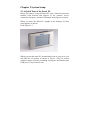
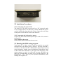
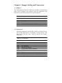
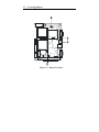
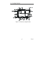
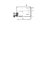
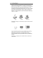
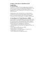
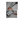
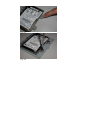
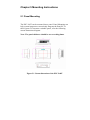
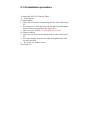
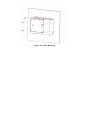
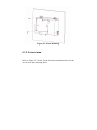
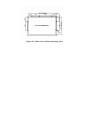
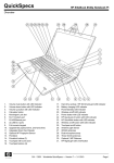
Panel PC user’s Manual ed1
PPC-L60T
VIA Eden Processor-based Fanless Panel PC
with 6.4 TFT LCD.
Contents
Chapter 1 General information
Chapter 2 System Setup
Chapter 3 Jumper Setting and Connectors
Chapter 4 Hardware Installation and Upgrading
Chapter 5 Mounting Instructions
Chapter 1 General information
1.1
Introduction
The PPC-L60T panel PC is a VIA low-power Eden processor
computer that is designed to serve as a human machine interface
(HMI) and as a multimedia computer. It is a PC based system with
6.4” color TFT LCF display and. Stainless enclosure, the
PPC-L60T is as compact and user friendly as a multi-function
computer.
For system integrators, this simple, complete, compact and high
integrated multimedia system lets you easily build a panel PC into
your application. Common industrial applications include factory
automation systems, precision machinery, and production process
control. It is also suitable for many nonindustry applications,
including car park automation and interactive Kiosk system. Our
Panel PC is a reliable, cost effective solution to your application’s
processing requirements.
1.2General Specifications
General
z Dimensions(WxHxD): 218x151x74.2 mm (8.58"X5.94"X2.92 ")
z Weight:1.8 kg (6.6 Ibs)
z Power supply: ATX type
Input Voltage:
12V dc -24 V dc, 3.5A max.
Output Voltage:
5V@5A, 12V@1A
z Power adaptor AC/DC
Input Voltage: 100~240V ac
Output Voltage:[email protected]
z
Disc Driver housing: Space for one 2.5”HDD.
z
Front Panel: IP65/NEMA compliant.
Standard PC functions
z CPU: Onboard VIA Eden™ 400 MHz processor
z
BIOS: Award 256 KB Flash BIOS.
z
System Chipset: VIA PN 133T Chipset
z
z
z
Front Side bus:133 MHz
2nd level cache: 64 KB on the Eden processor.
System Memory: One 144-pin SODIMM socket up to 512
MB SDRAM
Series ports: Two serial ports with two-232 ports, one is
RS232 ports; the other is RS-232/422/485 port. All ports are
compatible with 16C550UARTs, +5V/+12V power supply
selectable.
Universal serial bus (USB port: Support up to one USB port
and Intel UHC1v1.1 compatible.
SSD: Built in Type 1 Compact Flash socket, supports
Compact Flash card shared with one IDE channel.
Watchdog timer: 62-level, internal 1~62 seconds.
Automatically generates system reset or IRQ11 when the
system stops due to a program error or EMI. Jumperless
z
z
z
z
selection and software enabled/disabled.
Battery: 3.0V @ 195 Ma lithium battery
Audio function
Chipset: VIA82C686 South Bridge.
Audio controller: AC 97 Ver.2.0 compliant interface, Multi
stream direct sound and Direct Sound 3D acceleration.
Stereo Sound: 18 bit full-duplex codes.
Touch screen function:
Type
Analog Resistive
Resolution
Continuous
Light Transmission
80%
Controller
USB interface
Software Driver
Support Windows® 98/2000/XP
Durability
10million
(Touch in a lifetime)
Optional modules
Memory: up to 512 MB SDRAM (Standard is built-in 128 MB)
HDD: 2.5” HDD.
Operating System: Windows®
98/2000/XP/XPE/WinCE.NET4.2
Environmental Specifications
z
Operating Temperature 0-40° C
z
Relative Humidity
10~95% @ 40° C
(non-condensing)
z
Shock(Operating)
10G peak acceleration (11
ms.duration)
z
Vibration
1G
z
EMC
CE, FCC Class A
z
Safety
CE, UL
z
Front Panel Protection IP 65/ NEMA compliant
1.3 LCD specifications
z
z
z
z
z
z
z
z
Display Type
6.4” TFT LCD
Max. Resolution
600 X480
Colors
262K
Dot Size(mm)
0.203 x 0.203
Viewing Angle
90°
Luminance
150 cd/m2
Temperature
50° C
Backlight Lifetime 20,000hrs
Note: The color LCD display installed in the Panel PC is
high-quality and reliable. However, it may contain a few defective
pixls which don’t always illuminate. With current technology, it is
impossible to completely eliminate defective pixles. Advantech is
activity working to improve this technology.
Chapter 2 System Setup
2.1 A Quick Tour of the Panel PC
Before you start to set up the Panel PC, take a moment to become
familiar with location and purpose of the controls, driver,
connectors and ports, which are illustrated in the figures as below.
When you place the Panel PC upright on the desktop, its front
panel appears as shown
in the Figure 2-1.
When you turn the panel PC around and look at its rear cover, you
will find the I/O section as shown in Fig.2-2. (The I/O section
includes various I/O ports, including serial ports, the Ethernet port,
USB port, VGA port and so on.)
2.2 Installation Procedures
2.2.1 Connecting the power Cord
The Panel PC can only be powered by a DC electrical outlet
12~24 voltage, Max 3.5A). Be sure to always handle the power
cord by holding the plug ends only. Please connect the male plug
of the power cord to the DC inlet of the Panel PC.
2.2.2 Connecting the keyboard or mouse.
Connect the PS/2 mouse and keyboard port on the I/O section of
the Panel PC.
2.2.3 Switch on the power
Switch on the power switch on the rear cover.
2.3 Running the BIOS setup program
Your Panel PC is likely to have been the properly set up and
configured by your dealer prior to delivery. You may still find it
necessary to use the Panel PC’s BIOS (Basic Input-Output System)
setup program to change system configuration information, such
as the current date and time or your type of the hard drive. The
setup program is stored in ready-only memory (ROM).It can
either be accessed when you turn on or reset the panel PC, By
pressing the “ Del” Key on your keyboard immediately after
running the computer on.
The settings you specify with the setup program are recorded in s
special area of memory called CMOS RAM. This memory is
backed up by a battery so that it will not be erased when you turn
off or reset the system. Whenever you turn on the power, the
system reads the setting stored in CMOS RAM and compares
them to the equipment check conducted during the power on
self-test (POST).If an error occurs, an error message will be
displayed on screen, and you will be prompted to run the setup
program.
2.4 Installing the system software
Recent release of operating systems include setup program which
automatically load and guide you through hard disk preparation
and operating system installation. The guidelines below will help
you determine the steps necessary to install your operation system
on the Panel PC hard drive.
Note: Some distributors and system integrators may have already
pre-installed system software prior to shipment of your Panel PC.
Installed software requires an installed HDD. Software can be
loaded in the PPC-L60T using any of two methods.
2.4.1 Method 1: Use the Ethernet
You can use the Ethernet port to download software to the HDD.
2.4.2 Method 2: Use the COM
You can use the Lap Link 6 or similar transmission software.
Connect another PC to the PPC-L126 with an appropriate cable
and transmit the software to the PPC-L126.
2.5 Installing the Drivers
After installing your system software, you will be able to set up
the Ethernet, VGA, audio, and touch screen functions. All drivers
are stored in a CD-ROM disc entitled “Divers and Utilities” which
can be found in your assembly box.
The various drivers and utilities in the CD-ROM disc have their
own test files which help users install drivers and understand their
functions. These files are a very useful supplement to the
information in this manual.
Note: The drivers and utilities used for the PPC-L60T Panel PCs
are subject to change without notice. IF in doubt, check
Advantech’s website or contact our application engineers for the
latest information regarding drivers and utilities.
Chapter 3 Jumper Setting and Connectors.
3.1 Jumpers
The motherboard of the PPC-L60T has a number of jumpers that
allow you to configure your system to suit your application. The
table below lists the functions of the various jumpers.
Table 3.1: Jumpers
Label
S1
S2
S3
JP1
Function
Panel type select
CMOS clear button
System reset button
COM2 RS232/422/485 & WDT setting
3.2 Connectors
On-board connectors link the PPC-L60T to external devices
such as hard disk drives, a keyboard, or floppy drives. The
table below lists the func- tion of each of the board’s
connectors.
Table 3.2: Connectors
Label
Function
CN1
ATX feature
CN2
CPU fan power
CN3
Ext. flat panel
CN4
Flat panel connector
CN5
LCD Inverter control connector
CN6
LVDS connector
CN7
Main Power connector
CN8
ATX power on/off switch connector
CN9
Peripheral power connector (-5V, -12V)
Table 3.2: Connectors
CN10 PC/104 expansion
CN11 IDE hard drive connector
CN12 COM2 port connector
CN13 IR connector
CN14 Audio connector
CN15 Parallel port connector
CN16 Power & HDD LED connector
CN17 Ethernet connector
CN18 Keyboard and PS/2 mouse connector
CN19 USB channel 1, 2 connector
CN20 COM 1 port
CN21 CRT display
CN22 CFC connector
CN23 Floppy drive connector (optional)
3.3 Locating jumpers
Figure 3.1: Jumper locations
3.4 Locating Connectors
Figure 3.2: Connectors (component side)
11
2
Chapter
Figure 3.3: Connectors (solder side)
3.5 Setting Jumpers
You may configure your panel PC to match the needs of your
application by setting jumpers. A jumper is a metal bridge
used to close an electric cir- cuit. It consists of two metal pins
and a small metal clip (often protected by a plastic cover)
that slides over the pins to connect them. To “close” a jumper,
you connect the pins with the clip. To “open” a jumper, you
remove the clip. Sometimes a jumper will have three pins,
labeled 1, 2 and 3. In this case you would connect either pins
1 and 2, or 2 and 3.
open
closed
closed 2-3
The jumper settings are schematically depicted in this manual
as follows:.
open
closed
closed 2-3
A pair of needle-nose pliers may be helpful when working
with jumpers. If you have any doubts about the best
hardware configuration for your application, contact your
local distributor or sales representative before you make any
changes.
Generally, you simply need a standard cable to make most
connections.
3.6 Clear CMOS (S2)
Warning!
To avoid damaging the computer, always
turn off the power supply before setting
“Clear CMOS.” Before turning on the
power supply, set the jumper back to “3.0
V Battery On.”
This jumper is used to erase CMOS data and reset system
BIOS informa- tion.
The procedure for clearing CMOS is:
1. Turn off the system.
2. Short pin 2 and pin 3.
3. Return jumper to pins 1 and 2.
4. Turn on the system. The BIOS is now reset to its default
setting
Table 4.3: CMOS clear (S2)
Condition
unpressed*
pushed
CMOS
* default setting
Result
Normal
Clear
3.7 COM port connector (CN20,CN12)
The motherboard of PPC-L60T provides two serial ports
(COM1: RS-232; COM2: RS232/422/485) in one DB-9 connector (COM1) and one 14-pin
dual-inline, male header. It provides connections for serial
devices (a mouse, etc.) or a communication network. You can
find the pin assignments for the COM port connector in
Appendix C.
4.6.1COM2 RS-232/422/485 setting (pin 1-6 of JP1) COM2
can be configured to operate in RS-232, RS-422, or RS-485
mode. This is done via JP1
Table 2.4: JP1: COM2 RS-232/422/485 select
PINS
1-2
3-4
5-6
RS-232*
Open
Open
Closed
RS-422
Open
Closed
Open
RS-485
Closed
Open
Open
3.8 hernet configuration
The PCM-9373 is equipped with a high performance 32-bit
PCI-bus
Ethernet interface which is fully compliant with IEEE 802.3U
10/
100Mbps CSMA/CD standards. It is supported by all
major network operating systems.
The medium type can be configured via the
RSET8139.EXE program included on the utility disk. (See
Chapter 3 for detailed information.)
4.7.l1 100Base-T connector (CN17)
100Base-T connections are made via the on-board RJ-45
connector
4.7.2 Network boot
The Network Boot feature can be utilized by incorporating
the Boot ROM image files for the appropriate network
operating system. The Boot ROM BIOS files are included in
the system BIOS, which is on the utility CD disc.
3.9 Watchdog timer configuration
An on-board watchdog timer reduces the chance of
disruptions which EMP (electro-magnetic pulse) interference
can cause. This is an invalu- able protective device for
standalone or unmanned applications. Setup involves one
jumper and running the control software (refer to Appendix
A).
2.21.1 Watchdog timer action (pin 7-10 of JP1)
When the watchdog timer activates (CPU processing has
come to a halt), it can reset the system or generate an
interrupt on IRQ11. This can be set via setting JP1 as shown
below:
Table 2.6: JP1 Watchdog timer action
Pins
System reset*
IRQ11
7-8
closed
open
9-10
open
closed
* Default setting
3.10 USB connectors (CN19)
The PCM-9373 board provides up to four USB (Universal
Serial Bus)
ports. This gives complete Plug and Play, and hot
attach/detach for up to
127 external devices. The USB interfaces comply with USB
specification
Rev. 1.1, and are fuse protected.
The USB interface is accessed through two 5 x 2-pin
flat-cable connec- tors, CN19 (USB1, 2). You will need an
adapter cable if you use a stan- dard USB connector. The
adapter cable has a 5 x 2-pin connector on one end and a
USB connector on the other.
The USB interfaces can be disabled in the system BIOS setup.
Chapter 4 Hardware Installation and
Upgrading
4.1 Introduction
The panel PC consists a PC-based computer that is housed in a
metal rear cover and. You can install HDD, SDRAM and CF card
by removing the rear panel. Any maintenance or hardware
upgrades can be easily completed after removing the rear panel
and HDD bracket.
Warning! Don’t remove the metal rear cover until you have
verified that no power is following within the panel PC. Power
must be switched off and the powercord must be unplugged.
Every time you servie the Panel PC, you should be aware of this.
4.2 Installing the 2.5” Hard Disk Drive (HDD)
You can attach one enhanced Integrated Device Electronics (IDE)
Hard disk drive to the panel PC’S internal controller which uses a
PCI local-bus interface. The advanced IDE controller supports
faster data transfer and allows the IDE hard drive to exceed 512
MB. The following are instructions for installation:
1. Detach and remove the HDD bracket from rear cover.
2. Place the HDD on the Metal plate, and tighten the screws. (See
the Fig 4-1)
3. The Connect the HDD cable to the HDD.
4. put the rubber (see the Fig 4-2)
5. Put the damper on TOP OF the rubber. See the Fig 4-3)
6. Tighten screws. (See the Fig 4-4)
7. Put the HDD bracket and tighten the screws.
Fig 4-1
Fig 4-2
Fig 4-3
Fig 4-4
Chapter 5 Mounting Instructions
5.1 Panel Mounting
The PPC-L60T can be mounted into a panel. Panel Mounting can
help system integrators conveniently integrate the Panel PC in
their system. To construct a suitable panel, refer the following
cutout dimensions diagram.
Note: The panel thickness should be not exceeding 8mm.
Figure 5.1 Cutout dimension of the PPC-L60T.
5.1.2 Installation procedure
To mount the PPC-L60T into the Panel:
¾ Panel Mount
(1) Panel Mount
1. There are seven holes located along the four sides of the Panel
PC.
2. Insert the screws from the front side into the holes and tighten
them with the nuts provided.(See Figure E.2 )
3. The screw size is M3*L (L=wall thickness+5.0mm)
(2) Clamper Mount
1. There are four holes located along the four sides of the Panel
PC.
2. Insert the clamper from the four sides and tighten them with
the nuts provided.
3. The screw size is M4*12 mm
(See Figure5.3)
Figure 5.2 Panel Mounting
Figure 5.3 Panel Mounting
5.1.3 Cut-out area
Refer to Figure 5-3 below for the locations and dimensions for the
cut out area and mounting holes.
Figure 5.3: Dimension of Panel mounting holes.