1
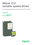
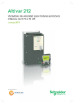
Variable speed drives Altivar 32 For 3-phase motors from 0.18 to 15 kW Catalogue April 2010 All technical information about products listed in this catalogue are now available on: www.schneider-electric.com Browse the “product data sheet” to check out: p characteristics, p dimensions, p curves, ... p and also the links to the user guides and the CAD files. 1 From the home page, type the model number* into the “Search” box. * type the model number without any blank, replace “p” by “ ” * 2 Under ”All” tab, click the model number that interests you. 3 The product data sheet displays. Example : Zelio Time data sheet Discover this product p Characteritics p Functions p Connection p Dimensions p Download & Documents Other products p Help me to choose Accessories p Plug p Sockets Example : Zelio Time data sheet 78 80 22,5 89,5 82 Example : Zelio Time data sheet U U C C G G R t1 t2 t'1 t'2 R t1 t2 t'1 t'2 You can get this information in one single pdf file. 1 2 3 4 5 6 7 8 10 2 Contents 0 Variable speed drives Altivar 32 b Offer for complex machines. . . . . . . . . . . . . . . . . . . . . . . . . . . . . . . . . . . page 4 b Presentation. . . . . . . . . . . . . . . . . . . . . . . . . . . . . . . . . . . . . . . . . . . . . . . . page 6 b Variable speed drives Altivar 32 1 v References . . . . . . . . . . . . . . . . . . . . . . . . . . . . . . . . . . . . . . . . . . . . . . page 12 b Options v v v v v v v Accessories. . . . . . . . . . . . . . . . . . . . . . . . . . . . . . . . . . . . . . . . . . . . . . Dialogue tools, configuration tools. . . . . . . . . . . . . . . . . . . . . . . . . . . . . Braking resistors . . . . . . . . . . . . . . . . . . . . . . . . . . . . . . . . . . . . . . . . . . Line chokes. . . . . . . . . . . . . . . . . . . . . . . . . . . . . . . . . . . . . . . . . . . . . . Motor chokes. . . . . . . . . . . . . . . . . . . . . . . . . . . . . . . . . . . . . . . . . . . . . Integrated EMC filters and additional EMC input filters. . . . . . . . . . . . . . Communication buses and networks. . . . . . . . . . . . . . . . . . . . . . . . . . . page 13 page 14 page 17 page 18 page 19 page 20 page 22 b SoMove setup software. . . . . . . . . . . . . . . . . . . . . . . . . . . . . . . . . . . . . . page 28 2 3 b Motor starters. . . . . . . . . . . . . . . . . . . . . . . . . . . . . . . . . . . . . . . . . . . . . . page 32 4 5 6 7 8 10 3 Offer for complex machines Altivar 32 variable speed drives and Lexium 32 motion control Application areas 1 Commons Printing, material handling, conveying, transfer machines, packaging, textiles, etc. Specific Hoisting, wood-working or metal processing machines, etc. Technology type Altivar 32 variable speed drives without sensor (velocity control) 2 3 4 Power range for 50…60 Hz (kW) line supply Drive 5 – Single-phase 200…240 V (kW) 0.18…2.2 Three-phase 380…480 V (kW) – Three-phase 380…500 V (kW) 0.37…15 Motor speed 0.1…599 Hz Type of control Motor sensor 6 7 10 Voltage/frequency ratios: U/f and 5-point U/f Sensorless flux vector control ratio Kn2 quadratic ratio (pump/fan) Energy saving ratio Synchronous motor Ratio for synchronous motor without sensor Integrated – Available as an option – Transient overtorque 170…200% of the nominal motor torque Peak current – 150 Safety functions Integrated 1: STO (Safe Torque Off) Available as an option 3: SLS (Safe Limited Speed), SDI (Safe Direction Information), SS1 (Safe Stop 1) Inputs Outputs 9 Asynchronous motor Number of functions Number of I/O 8 0.18…15 Single-phase 100…120 V (kW) Communication Analog 3 Logic 6 Analog 1: configurable as voltage (0-10 V) or current (0-20 mA) Logic 1 Relay outputs 2 Integrated Modbus, CANopen Available as an option DeviceNet, PROFIBUS DP V1, EtherNet/IP, Modbus TCP, EtherCat (r) Bluetooth link® Integrated Options SoMove setup software Multi-Loader configuration tool Graphic display terminal Filters, braking resistors, line chokes Standards and certifications IEC 61800-5-1, IEC 61800-3 (environments 1 and 2, category C2), UL 508C, EN 954-1 category 3, ISO/EN 13849-1/- 2 category 3 (PL d), IEC 61508 (parts 1 & 2) SIL 2 level, draft standard EN 50495E e, UL, CSA, C-Tick, NOM, GOST References Pages ATV 32 12 r Available 3rd quarter 2010 More technical information on www.schneider-electric.com . . . please consult the end pages of this catalogue Printing, material handling, conveying, transfer machines, packaging, textiles, etc. Clamping, cutting, cutting to length, flying shear, rotary knife, Pick & Place, winding, marking, etc. 1 Lexium 32 servo drives with sensor feedback (position control) 2 BMH servo motor BMH Servo motor BSH Servo motor BMH Servo motor BSH Servo motor BSH Servo motor 0.15…7 3 4 0.15…0.8 0.3…1.6 0.4…7 – Nominal speed: b BMH servo motors: continuous stall torque range between 1.2…84 Nm for nominal speeds between 1200 and 6000 rpm b BSH servo motors: continuous stall torque range between 0.5…33.4 Nm for nominal speeds between 2500 and 6000 rpm 5 – Synchronous motor with sensor feedback for BMH and BSH servo motors SinCos Hiperface® sensor – Resolver encoder Analog encoder (motor and machine) Digital encoder (machine only) 6 – Peak current, up to 4 times the drive direct current for 1 second – 1: STO (Safe Torque Off) 7 4: SLS (Safe Limited Speed), SS1 (Safe Stop 1), SS2 (Safe Stop 2), SOS (Safe Operating Stop) 2 – – 6 4 (1 of which can be used as a capture input) 6 (2 of which can be used as a capture input) – – – 5 2 3 – – – Modbus Modbus, CANopen, CANmotion Modbus – – CANopen, CANmotion, DeviceNet, EtherNet/IP, PROFIBUS DP V1, EtherCat (r) Available as an option Available as an option Available as an option 8 SoMove setup software Multi-Loader configuration tool Graphic display terminal Filters, braking resistors, line chokes 9 IEC 61800-5-1, IEC 61800-3 (environments 1 and 2, categories C2 and C3), IEC 61000-4-2/4-3/4-4/4-5, ISO/EN 13849-1 (PL e), IEC 61508 SIL 3 level e, UL, CSA, TÜV LXM 32C LXM 32A 10 LXM 32M Consult our catalogue “Lexium 32 motion control” r Available 3rd quarter 2010 More technical information on www.schneider-electric.com . . . please consult the end pages of this catalogue Presentation Variable speed drives Altivar 32 Presentation PF095109 1 The Altivar 32 drive is a frequency inverter for 200…500 V three-phase asynchronous and synchronous motors rated from 0.18 to 15 kW. By taking account of constraints on product setup and use right from the design stage, we are able to simplify its integration into industrial machines. The Altivar 32 drive features more than 150 functions and is robust, compact and easy to install. Up to 4 kW, the Altivar 32 drive is 45 or 60 mm wide, saving a considerable amount of space in an installation. It has also been designed to be mounted side by side or on its side in densely-packed or shallow enclosures. 2 270 mm 3 Example with six 45 mm wide drives mounted side-by-side The Altivar 32 drive also offers functions which satisfy the demands of specific applications: b The safety function guarantees a high level of safety (SIL 2 according to standard IEC 61508) comparable with performance level “d” (PL d) according to ISO/EN 13849-1/-2. b The ATV Logic function offers simple control system functions (Boolean, arithmetical operations, comparators, etc.). With various communication cards available as options, the Altivar 32 drive integrates perfectly into the main control system architectures. 4 PF600365 The Altivar 32 drive includes various motor control profiles for three-phase asynchronous motors. It also features a special control profile for permanent magnet synchronous motors. Being compact and highly energy efficient, these motors are particularly suitable for conveying applications. 5 6 Synergy between Altivar 32 drive and Lexium 32 servo drive (1) 7 Simplified setup and use Examples of solutions to simplify setup and use: b Compatibility with all dialogue and configuration tools for Altivar 32 variable speed drives and Lexium 32 servo drives (SoMove setup software, SoMove Mobile software for mobile phones, remote display terminals and the Simple Loader and Multi-Loader configuration tools) b Built-in Bluetooth® link b Easy-fit communication cards in cassette format b Optimised offer for connection to the CANopen machine bus b Different mounting options depending on the machine (vertical, horizontal, with the option to offset the control module when the drive is mounted on its side (to save space depthwise), side-by-side) b Quick connect for a TeSys GV2 L magnetic circuit-breaker (which can be equipped with numerous TeSys accessories) b Labelled terminals b Synergy with Lexium 32 servo drives for controlling applications involving asynchronous and synchronous motors (common tools and options, same shape and dimensions, etc.) The Altivar 32 drive is also compatible with SoMachine, the software solution for OEMs. This solution can be used to develop, configure and set up an entire machine in a single software environment. Applications PF600365 8 The Altivar 32 drive incorporates functions which are suitable for the most common applications, including: b Material handling (small conveyors, hoists, etc.) b Packing and packaging machines (small bagging machines, labelling machines, etc.) b Special machines (mixers, kneaders, transfer machines, textile machines, etc.) b Pumps, compressors, fans b Hoisting b Wood-working machinery (saws, gummers, planers, etc.) b Metal processing (bending presses, welding machines, cutting machines, etc.) 9 (1) Please refer to the “Lexium 32 motion control” catalogue. 10 Conveying application References: page 12 Presentation (continued) Main functions (1) Variable speed drives Altivar 32 The Altivar 32 drive has six logic inputs, three analog inputs, one logic/analog output and two relay outputs. PF600366 Application functions The Altivar 32 drive includes 150 functions for handling, in particular: b Configurations: standard or customisable b Settings: factory or OEM b Application-specific functions (conveying, cutting, hoisting, etc.) b The adjustable switching frequency for optimizing servo control (adjusted motor current, reduced motor noise and temperature rise, etc.) b The various Human-Machine Interfaces (HMIs) and dialogue or configuration tools b Menu parameter setting, using the “My Menu” function to obtain an applicationspecific Human-Machine Interface (HMI) b Uploads and downloads of application and drive software, with the power on or off Example of an application requiring the use of safety functions Safety functions The Altivar 32 drive software includes three safety functions which contribute to ensuring machines meet safety requirements, whether or not they are used in conjunction with a Preventa safety module (2): b STO: Safe Torque Off b SLS: Safely Limited Speed b SS1: Safe Stop 1 These safety functions are configured via the SoMove setup software (see page 28). 1 2 3 4 PF600367 Note: To set up the safety functions, please refer to the “Safety Integrated function” manual, which is available on our website at “www.schneider-electric.com”. ATV Logic The integrated control system functions featuring ATV Logic can be used to perform simple operations without adding further devices. ATV Logic is programmed via the SoMove setup software (see page 28) and provides access to the following functions: b Arithmetical operations, Boolean operators, counters, timers, etc. b Programming of up to 50 functions by an automated sequence b Access to the drive's internal variables Example of an application requiring a typical ATV Logic sequence Motor control profiles for asynchronous and synchronous motors The drive features different motor control profiles: b For asynchronous motors: v Two voltage/frequency ratios: U/f and 5-point U/f v Sensorless flux vector control ratio v Kn2 quadratic ratio (pump/fan) v Energy saving ratio b For synchronous motors: Permanent Magnet motor control profile 5 6 7 Examples of use (functions/applications) Functions Applications Handling Conveying Packing Wood-working machinery 8 Metal processing Safety functions Communication buses and networks Fast response time Control profile for synchronous motors Application-specific functions Typical use Not applicable 9 (1) Non-exhaustive list; please consult our website “www.schneider-electric.com”. (2) Please refer to the "Safety functions and solutions using Preventa" catalogue. 10 References: page 12 Presentation (continued) Variable speed drives Altivar 32 The offer The Altivar 32 range of variable speed drives covers motor power ratings from 0.18 kW to 15 kW with two types of power supply: b 200 V…240 V single-phase, 0.18 kW to 2.2 kW (ATV 32HpppM2) b 380 V…500 V three-phase, 0.37 kW to 15 kW (ATV 32HpppN4) Several drives can be mounted side by side to save space. 1 2 3 ATV 32H018M2...H075M2 ATV 32H037N4...HU15N4 ATV 32HU11M2...HU22M2 ATV 32HU22N4...HU40N4 In addition to the Modbus and CANopen protocols which can be accessed as standard, the Altivar 32 drive can be connected to the main industrial communication buses and networks by adding one of the communication cards available as an option: b Modbus/TCP - Ethernet/IP serial link b PROFIBUS DP V1, DeviceNet b EtherCAT (r) See page 22. 4 CANopen communication card with RJ45 connectors 5 6 The Altivar 32 drive integrates the Modbus and CANopen communication protocols as standard. They can be accessed via the RJ45 connector on the front of the drive. To simplify connection of the Altivar 32 drive to the CANopen machine bus, three dedicated communication cards are available with different connectors: b CANopen daisy chain card with two RJ 45 connectors b CANopen card with 9-way SUB-D connector b CANopen card with 5-way terminal block See pages 24 and 25. CANopen communication card with SUB-D connector CANopen communication card with connection via terminals 7 Electromagnetic compatibility (EMC) The built-in EMC filters in ATV 32HpppM2 and ATV 32HpppN4 drives and compliance with EMC requirements simplify installation and provide a very economical means of ensuring devices meet the criteria to receive the e mark. This enables compliance with standard IEC 61800-3, category C2 for a maximum motor cable length of 10 metres. This filter can be disconnected via a jumper. Filters are available as an option and can be installed by the customer to reduce the level of emissions from Altivar 32 drives. In particular, they allow use of a maximum motor cable length of 50 metres. See page 20. External accessories and options External accessories and options can be used with the Altivar 32 drive. The availability of external accessories and options depends on the drive rating. Accessories b Bracket for direct mounting of GV2/ATV 32 circuit-breaker (see page 32) b Adaptor for mounting the control module at 90°, for mounting the power module on its side, keeping the control module visible and accessible b Daisy chain DC bus cordsets for daisy chain connection of the DC bus See page 13. 8 External options b Braking resistors b Line chokes b Motor chokes b Additional EMC filters See pages 17 to 21. 9 GV2/ATV 32 direct mounting 10 r Available third quarter 2010 References: page 12 Variable speed drives Presentation (continued) Altivar 32 The offer (continued) Dialogue and configuration tools Human-Machine interface 3 The 4-digit display 1 displays drive states, faults and parameter values. The navigation button 2 is used to navigate through the menus, modify values and change the motor speed in local mode. 1 HMI terminals 1 2 The Altivar 32 drive can be connected to a remote display terminal 4 or a remote graphic display terminal 3, which are available as options. The remote terminal can be mounted on an enclosure door with IP 54 or IP 65 degree of protection. It provides access to the same functions as the Human-Machine interface. The remote graphic display terminal, with its text display in the user's language, provides a user-friendly interface for configuration, debugging or maintenance. It can also be mounted on an enclosure door with IP 54 or IP 65 degree of protection. See page 14. 4 2 3 SoMove setup software The SoMove setup software is used to configure, adjust, debug (using the Oscilloscope function) and maintain the Altivar 32 drive in the same way as for all other Schneider Electric drives and starters. It can be used with a direct connection or a Bluetooth® wireless connection. See page 28. 5 4 SoMove Mobile software for mobile phones 6 The SoMove Mobile software is used to edit the drive parameters from a mobile phone via a Bluetooth® wireless connection. It can also be used to save configurations. These configurations can be imported or exported from a PC via a Bluetooth® wireless connection. See page 16. 5 Simple Loader and Multi-Loader configuration tools The Simple Loader tool 6 enables the configuration from one powered-up drive to be duplicated on another powered-up drive. The Multi-Loader tool 5 enables configurations from a PC or drive to be copied and duplicated on another drive; the drives do not need to be powered up. See page 16. 6 Description 7 8 9 10 1 to 6, see “Dialogue and configuration tools” above. 7 Power terminals 8 Protective cover to prevent access to the power terminals 7 when closed 9 RJ 45 communication port for access to integrated protocols: Modbus serial link and CANopen machine bus 10 Protective cover for access to the control terminals (also includes a label with a wiring diagram) 11 Removable motor power terminal block (allows the connection memory to be retained during maintenance operations) 12 EMC mounting plate (integral part of the motor power terminal block 11). This plate is supplied with a cable guide support, which can be fitted if required. 11 12 7 8 9 10 References: page 12 Variable speed drives Presentation (continued) 1 2 3 4 5 f (Hz) 0 t (s) STO activation (zero torque) These three functions are certified in accordance with IEC 61800-5-2 Ed.1 “Adjustable speed electrical power drive systems - Part 5-2: Safety requirements Functional”. This integration makes it possible to: b Simplify setup of machines which require a complex safety device b Improve performance during maintenance by reducing machine or installation downtimes and increase the safety of any work carried out Activation of the STO safety function Note: Some applications may require the addition of external Preventa safety modules (2). Holding at a Freewheel predefined frequency stop f (Hz) Safe Torque Off (STO) safety function (1) The STO integrated safety function causes a motor freewheel stop by eliminating the torque on the motor shaft. Nominal frequency Predefined frequency 0 f max. t (s) STO activation (zero torque) if the predefined frequency is exceeded SLS activation Activation of the SLS safety function Safe stop according to a predefined ramp SS1 activation Activation of the SS1 safety function 8 9 10 References: page 12 10 STO activation (zero torque) Safely Limited Speed (SLS) safety function (1) The SLS integrated safety function slows down then holds the motor at a predefined frequency. If this predefined frequency cannot be held above a certain value, for example in the case of a driving load, the STO function is activated. Safe Stop 1 (SS1) safety function (1) The SS1 integrated safety function causes a category 1 safe stop. This stop occurs in the following sequence: b The motor is stopped according to a predefined deceleration ramp. b A check is made to ensure that the motor has stopped or that the frequency has been reached. b The STO function is activated. Setting up the integrated safety functions (1) Setting up the integrated safety functions in the Altivar 32 drive does not require any options or additional accessories. The functions are connected directly to the drive's logic inputs and can be configured using the SoMove setup software (see page 28). Nominal frequency 0 7 Integrated safety functions (1) The Altivar 32 drive includes three safety functions: b STO: Safe Torque Off b SLS: Safely Limited Speed b SS1: Safe Stop 1 Freewheel stop Nominal frequency f (Hz) 6 Altivar 32 t (s) (1) Please refer to the “Safety Integrated function” manual, which is available on our website at “www.schneider-electric.com”. (2) Please refer to the "Safety functions and solutions using Preventa" catalogue. Presentation (continued) Variable speed drives Altivar 32 Standards and certifications (1) Altivar 32 drives have been developed to conform to the strictest international standards and recommendations relating to industrial electrical control devices (IEC), in particular: b IEC 61800-5-1 b IEC 61800-3: v EMC immunity: IEC 61800-3, Environments 1 and 2 v Conducted and radiated EMC emissions: IEC 61800-3, category C2 b ISO/EN 13849-1/-2 category 3(PL d) b IEC 61508 (parts 1 & 2) 1 2 Altivar 32 drives are certified: b UL 508c b CSA b NOM b GOST b C-Tick They are e marked according to the European low voltage (2006/95/EC) and EMC (2004/108/EC) directives. They also comply with environmental directives (RoHS). (1) Complete list of certifications and characteristics available on our website “www.schneider-electric.com” 3 4 5 6 7 8 9 10 References: page 12 11 Variable speed drives References Altivar 32 Drives PF095103 1 Drives (frequency range from 0.1 to 599 Hz) 2 ATV 32H018M2...H075M2 ATV 32H037N4...HU15N4 kW HP Apparent Max. power prospec tive line Isc (3) Altivar 32 Max. continuous output current (In) (4) at U1 at U2 at U2 at U2 A kVA A kA A Maximum transient current for 60 s Power Reference dissipated at maximum output current (In) (4) A W Weight kg 5 0.18 0.37 0.55 0.75 1.1 1.5 2.2 1/4 1/2 3/4 1 11/2 2 3 3.4 6 7.9 10.1 13.6 17.6 23.9 2.8 5 6.7 8.5 11.5 14.8 20.1 0.7 1.2 1.6 2 2.8 3.6 4.8 1 1 1 1 1 1 1 1.5 3.3 3.7 4.8 6.9 8 11 2.3 5 5.6 7.2 10.4 12 16.5 25 38 42 51 64 81 102 ATV 32H018M2 ATV 32H037M2 ATV 32H055M2 ATV 32H075M2 ATV 32HU11M2 ATV 32HU15M2 ATV 32HU22M2 2.400 2.400 2.400 2.400 2.900 2.900 2.900 Three-phase supply voltage: 380…500 V 50/60 Hz, with integrated EMC filter (2) (5) (6) 4 ATV 32HU11M2...HU22M2 ATV 32HU22N4...HU40N4 0.37 1/2 2.1 1.6 1.4 5 1.5 2.3 27 ATV 32H037N4 2.500 0.55 3/4 2.8 2.2 1.9 5 1.9 2.9 31 ATV 32H055N4 2.500 0.75 1 3.6 2.7 2.3 5 2.3 3.5 37 ATV 32H075N4 2.500 1.1 11/2 5 3.8 3.3 5 3 4.5 50 ATV 32HU11N4 2.500 1.5 2 6.5 4.9 4.2 5 4.1 6.2 63 ATV 32HU15N4 2.500 2.2 3 8.7 6.6 5.7 5 5.5 8.3 78 ATV 32HU22N4 3.000 3 – 11.1 8.4 7.3 5 7.1 10.7 100 ATV 32HU30N4 3.000 4 5 13.7 10.5 9.1 5 9.5 14.3 125 ATV 32HU40N4 3,000 5.5 71/2 20.7 14.5 17.9 22 14.3 21.5 233 ATV 32HU55N4 7.500 7.5 10 26.5 18.7 22.9 22 17 25.5 263 ATV 32HU75N4 7.500 11 15 36.6 25.6 31.7 22 27.7 41.6 403 ATV 32HD11N4 8.700 15 20 47.3 33.3 41 22 33 49.5 480 ATV 32HD15N4 8.800 PF095105 6 Line supply Max. line current (1), (2) Single-phase supply voltage: 200…240 V 50/60 Hz, with integrated EMC filter (2) (5) (6) PF095104 3 Motor Power indicated on rating plate Dimensions (overall) Drives 7 ATV 32HU55N4, HU75N4 EMC plate not mounted LxHxD EMC plate mounted EMC plate not mounted mm mm ATV 32H018M2...H075M2, ATV 32H037N4...HU15N4 45 x 317 x 245 – (6) ATV 32HU11M2...HU22M2, ATV 32HU22N4...HU40N4 60 x 317 x 245 – (6) ATV 32HU55N4, HU75N4 150 x 308 x 232 150 x 232 x 232 ATV 32HD11N4, HD15N4 180 x 404 x 232 180 x 330 x 232 PF095106 (1) Typical value for a 4-pole motor and a maximum switching frequency of 4 kHz, with no line choke for max. prospective line Isc (3). (2) Nominal supply voltage, min. U1, max. U2: 200 (U1)…240 V (U2), 380 (U1)…500 V (U2). (3) If line Isc is greater than the values in the table, add line chokes (see page 18). (4) These values are given for a nominal switching frequency of 4 kHz, for use in continuous operation. The switching frequency is adjustable from 2 to16 kHz. Above 4 kHz, derate the nominal drive current. The nominal motor current should not exceed this value. See the derating curves on our website www.schneider-electric.com. (5) Drives supplied with category C2 integrated EMC filter. This filter can be disconnected. (6) Connection in compliance with EMC standards: - ATV 32HpppM2, ATV 32H037N4...HU40N4 drives are supplied with an EMC plate. This is an integral part of the power terminals; these 2 components cannot be separated. - ATV 32HU55N4…HD15N4 drives are supplied with an EMC plate, for assembly by the customer. 8 9 ATV 32HD11N4, HD15N4 EMC plate not mounted 10 Presentation: page 6 12 Variable speed drives References (continued) Altivar 32 Accessories, documentation PF095123 Accessories Components for mounting GV2 circuit-breaker directly on ATV 32 drive Description ATV 32HU15N4 with control module mounted at 90° For drives Sold in lots Unit of reference Weight kg Bracket for GV2/ATV 32 direct mounting ATV 32HpppM2 10 Mechanical bracket for holding the GV2 circuit-breaker in ATV 32H037N4…HU40N4 place when directly mounted on ATV 32 drive. Requires a GV2 AF4 adaptor plate for electrical connection, to be ordered separately. VW3 A9 921 0.075 Adaptor plate Provides the electrical link between the GV2 circuitbreaker and ATV 32 drive when GV2/ATV 32 directly mounted. Requires a VW3 A9 921 bracket for direct mounting, to be ordered separately. ATV 32HpppM2 10 ATV 32H037N4…HU40N4 GV2 AF4 0.016 For drives Reference ATV 32HpppM2 ATV 32H037N4…HU40N4 VW3 A9 920 Mounting the control module at 90° Description PF095121 Adaptor for mounting the control module at 90° This is used to mount the power module on the side, keeping the control module visible and accessible Weight kg 0.125 Daisy Chain connection of the DC bus (1) The DC bus is connected in a Daisy Chain in the following cases: b Drives powered by the AC supply with parallel connection of the DC bus in order to balance the loads during braking phases between the drives; used in addition to braking resistors (see page 17) b Drives powered by the DC bus only 1 2 3 4 Requires the cordsets listed below: Description Daisy chain DC bus cordsets (1) ATV 32HpppM2 connected with a Daisy Chain DC bus cordset Use Length Reference Weight From To m ATV 32HpppM2 ATV 32HpppM2 0.18 VW3 M7 101 R01 – ATV 32H037N4… HU40N4 ATV 32H037N4… HU40N4 Fitted with one ATV 32H037N4… connector and HU40N4 flying leads at one end ATV 32HU55N4… HD15N4 1.5 VW3 M7 102 R15 – Fitted with 2 connectors LEX 32ppppM2 (2) LEX 32ppppN4 (2) 0.65 Fitted with 2 connectors ATV 32HpppM2 ATV 32HpppN4 Documentation Description “Description of the Motion & Drives offer” DVD-ROM Comprises (3): b Technical documentation (programming manuals, installation manuals, quick reference guides) b Catalogues b Brochures kg 5 6 VW3 M7 101 R06 Reference VW3 A8 200 – Weight kg 0.100 (1) Setting up several devices on the DC bus requires special precautions, please refer to the installation manual which is available on our website at www.schneider-electric.com. (2) Lexium 32 motion control offer. See page 4 and please refer to our “Lexium 32 motion control” catalogue. (3) The contents of this DVD-ROM are also available on our website www.schneider-electric.com. 7 8 9 10 Presentation: page 6 13 Variable speed drives Presentation, references Altivar 32 Option: dialogue tools, configuration tools 1 PF095133 Remote display terminal 1 4 2 3 2 Remote display terminal with cover open PF095131 3 This terminal is used to locate the Human-Machine Interface of the Altivar 32 drive remotely on the door of an enclosure with IP 54 or IP 65 protection. It is used to: b Control, adjust and configure the drive remotely b Display the drive status and faults remotely Its maximum operating temperature is 50°C. Description 1 4-digit display 2 Navigation , and selection ENT, ESC keys 3 Motor local control keys: - RUN: Starts the motor - FWD/REV: Reverses the direction of rotation of the motor - STOP/RESET : Stops the motor/resets drive faults 4 Operating mode selection key MODE 5 Cover controlling access to the motor local control keys References Designation 5 4 Degree of Length protection Reference m Remote display terminal with cover closed Weight kg Remote display terminals A remote-mounting cordset VW3 A1 104 Rpp is also required IP 54 – VW3 A1 006 0.250 IP 65 – VW3 A1 007 0.275 Remote-mounting cordsets fitted with 2 RJ45 connectors – 1 VW3 A1 104 R10 0.050 3 VW3 A1 104 R30 0.150 Remote graphic display terminal PF600255 5 6 6 7 8 7 9 8 9 Remote graphic display terminal 8 9 10 Presentation: page 6 14 This graphic display terminal, common to all Schneider Electric's variable speed drive ranges, provides a user-friendly interface for configuration, debugging and maintenance. In particular, it is possible to transfer and store up to 4 configurations. For portable use or mounted on an enclosure door, it can also be connected to a number of drives (see page 15). Its main functions are as follows: b The graphic screen displays 8 lines of 24 characters of plain text. b The navigation button provides quick and easy access to the drop-down menus. b It is supplied with six languages installed (Chinese, English, French, German, Italian and Spanish). The available languages can be modified using the MultiLoader configuration tool (VW3 A8 121). Its maximum operating temperature is 60°C, and it features IP 54 protection; this can be increased to IP 65 when mounted on an enclosure door. Description 6 Graphic display: - 8 lines of 24 characters, 240 x 160 pixels, large digit display 7 Function keys (not operational on the Altivar 32) 8 Navigation button: - Rotate ±: Goes to the next/previous line, increases/decreases the value - Press: Saves the current value (ENT) ESC key: Aborts a value, a parameter or a menu to return to the previous selection 9 Motor local control keys: - RUN: Starts the motor - STOP/RESET : Stops the motor/resets drive faults - FWD/REV: Reverses the motor direction of rotation Variable speed drives Presentation, references Altivar 32 Option: dialogue tools, configuration tools DF600259 Remote graphic display terminal (continued) Accessories for mounting the graphic display terminal remotely 3 Description Item no. Length m Reference 1 – VW3 A1 101 0.180 Remote-mounting cordsets 2 fitted with 2 RJ45 connectors For remote mounting of the Altivar 71 drive and graphic display terminal VW3 A1 101 1 VW3 A1 104 R10 0.050 3 VW3 A1 104 R30 0.150 5 VW3 A1 104 R50 0.250 10 VW3 A1 104 R100 0.500 Female/female RJ45 adaptor 3 – VW3 A1 105 0.010 Remote mounting kit For mounting on enclosure door IP 54 degree of protection 4 – VW3 A1 102 0.150 Door Used to increase the degree of protection for remote mounting kit VW3 A1 102 to IP 65 To be mounted on remote mounting kit VW3 A1 102 5 – VW3 A1 103 0.040 Remote graphic display terminal A remote-mounting cordset VW3 A1 104 Rppp and an RJ45 adaptor VW3 A1 105 must be provided 1 2 DF600260 Portable use of the portable graphic display terminal: 1 + 2 + 3 4 Weight kg 1 2 3 4 1 Additional accessories for multidrop connection Description 2 5 Using the graphic terminal on enclosure door: 1 + 2 + 4 (+ 5, if IP 65) Item no. Modbus splitter box 10 RJ45 connectors and 1 screw terminal block 6 Sold in lots of – Modbus T-junction boxes With integrated cable (0.3 m) 7 – VW3 A8 306 TF03 – With integrated cable (1 m) 7 – VW3 A8 306 TF10 – Modbus line terminator For RJ45 connector 8 2 VW3 A8 306 RC Item no. Length m Reference 9 0.3 VW3 A8 306 R03 0.025 1 VW3 A8 306 R10 0.060 3 VW3 A8 306 R30 0.130 R = 120 W, C = 1 nf Description Cordsets for Modbus serial link equipped with 2 RJ45 connectors 2 7 2 7 Unit reference LU9 GC3 Weight kg 0.500 0.010 VW3 A1 102 6 Weight kg Example of connection via multidrop link All the components described on this page enable a graphic display terminal to be connected to several drives via a multidrop link. This multidrop link is connected to the RJ45 port on the Modbus/CANopen communication port. See the example opposite. 4 5 7 8 ATV 32 6 9 9 7 9 7 7 8 9 7 8 10 ATV 32 Example of connection via multidrop link Presentation: page 6 15 Variable speed drives Presentation, references Altivar 32 Option: configuration tools SoMove Mobile software for mobile phones (1) 1 The SoMove Mobile software “transforms” any compatible mobile phone (1) into a remote graphic display terminal by offering an identical Human-Machine Interface (see page 14). Particularly suitable for on-site or remote maintenance operations, the SoMove Mobile software can be used to print out and save configurations, import them from a PC and export them to a PC, or a drive, equipped with Bluetooth®. 2 The SoMove Mobile software and drive configuration files can be downloaded from our website www.schneider-electric.com. References Description Configuration with SoMove Mobile software for mobile phones via Bluetooth® 3 For drives SoMove Mobile software for mobile phones ATV 32Hppppp (1) Can be downloaded from our website www.schneider-electric.com. Reference Weight kg – – SoMove setup software PF095122 For presentation, description and references, see page 28. Simple Loader and Multi-Loader configuration tools The Simple Loader tool enables one powered-up drive's configuration to be duplicated on another powered-up drive. It is connected to the drive's RJ45 communication port. PF080628 4 SoMove lite setup software for PC is used to prepare drive configuration files. 5 VW3 A8 121 VW3 A8 120 The Multi-Loader tool enables a number of configurations from a PC or drive to be copied and loaded onto another drive; the Altivar 32 drives do not need to be powered up. References Description 6 PF600325 Simple Loader configuration tool Supplied with a cordset fitted with 2 RJ45 connectors. 7 8 Multi-Loader configuration tool Configuring an Altivar 32 in its packaging: VW3 A8 121 + VW3 A8 126 cordset 9 10 Presentation: page 6 16 Reference Weight kg ATV 32Hppppp VW3 A8 120 – Multi-Loader configuration tool ATV 32Hppppp Supplied with: - 1 cordset fitted with 2 RJ45 connectors - 1 cordset fitted with one type A USB connector and one mini B USB connector - 1 x SD memory card - 1 x female/female RJ 45 adaptor - 4 AA/LR6 1.5 V batteries - 1 anti-shock protection - 1 carrying handle VW3 A8 121 – Cordset for Multi-Loader tool ATV 32Hppppp in VW3 A8 126 For connecting the Multi-Loader tool to the its packaging Altivar 32 drive in its packaging. Fitted with a non-locking RJ45 connector with special mechanical catch on the drive end and an RJ45 connector on the Multi-Loader end. – (1) SoMove Mobile software requires a mobile phone with minimum features; please consult our website www.schneider-electric.com. Variable speed drives Presentation, references Altivar 32 Option: braking resistors Presentation The braking resistor enables the Altivar 32 drive to operate while braking to a standstill or during slowdown braking, by dissipating the braking energy. It enables maximum transient braking torque. 1 Depending on the drive rating, two types of resistor are available: b Enclosed model (IP 20 casing) designed to comply with the EMC standard and protected by a temperaturecontrolled switch or thermal overload relay. b Enclosed model (IP 65 casing) with cordset, for ATV 32HpppM2 and ATV 32H037N4…HU75N4 drives. Note: To optimize the size of the braking resistor, the DC buses on Altivar 32 drives in the same application can be connected in parallel (see 13). 2 Applications Machines with high inertia, driving loads and machines with fast cycles. References For drives Minimum Ohmic value of the value resistor to be connected Average power available at 50°C (1) Length of connection cable Reference Weight W W W m ATV 32H018M2…H075M2 40 100 25 0.75 VW3 A7 608 R07 0.410 ATV 32H037…H075N4 80 3 VW3 A7 608 R30 0.760 ATV 32HU11N4…HU22N4 54 ATV 32HU11M2, HU15M2 27 0.75 VW3 A7 605 R07 0.620 3 VW3 A7 605 R30 0.850 0.75 VW3 A7 603 R07 0.930 3 VW3 A7 603 R30 1.200 0.75 VW3 A7 606 R07 0.930 3 VW3 A7 606 R30 1.200 0.75 VW3 A7 604 R07 1.420 3 VW3 A7 604 R30 1.620 – VW3 A7 701 2.000 kg PF106005 IP 65 braking resistors VW3 A7 608 Rpp ATV 32HU22M2 25 ATV 32HU30N4 54 ATV 32HU40N4 36 ATV 32HU55N4, HU75N4 27 72 27 72 27 25 50 50 100 3 4 5 6 PF105659 IP 20 braking resistors VW3 A7 701 ATV 32H018M2…H075M2 40 ATV 32HU11M2, HU15M2 27 ATV 32H037N4…H075N4 80 ATV 32HU11N4…HU30N4 54 ATV 32HU40N4 36 ATV 32HU22M2 25 ATV 32HU55N4, HU75N4 27 ATV 32HD11N4, HD15N4 16 100 50 7 60 100 – VW3 A7 702 2.400 28 200 – VW3 A7 703 3.500 (1) Load factor for resistors: the value of the average power that can be dissipated at 50°C from the resistor into the casing is determined for a load factor during braking that corresponds to the majority of normal applications: - 2 s braking with a 0.6 Tn braking torque for a 40 s cycle - 0.8 s braking with a 1.5 Tn braking torque for a 40 s cycle 8 9 10 Presentation: page 6 17 Variable speed drives Presentation, references Altivar 32 Option: line chokes Presentation 1 Line choke M1 3 2 ∿ ATV 32HpppM2 M1 3 3 ∿ ATV 32HpppN4 3 The recommended chokes limit the line current. They have been developed in line with standard IEC 61800-5-1 (VDE 0160 level 1 high-energy overvoltages on the line supply). The inductance values are defined for a voltage drop between 3% and 5% of the nominal line voltage. Values higher than this will cause loss of torque. Line choke 2 Line chokes provide improved protection against overvoltages on the line supply and reduce harmonic distortion of the current produced by the drive. The use of line chokes is recommended in particular under the following circumstances: b Line supply with significant disturbance from other equipment (interference, overvoltages) b Line supply with voltage imbalance between phases > 1.8% of nominal voltage b Drive supplied by a line with very low impedance (in the vicinity of a power transformer 10 times more powerful than the drive rating) b Installation of a large number of frequency inverters on the same line b Reduction of overloads on the cos j correction capacitors, if the installation includes a power factor correction unit The prospective short-circuit current at the point of connection of the drive must not exceed the maximum value indicated in the reference tables (see page 12). The use of chokes allows connection to the following line supplies: b Max. Isc 22 kA for 200/240 V b Max. Isc 65 kA for 380/500 V 4 References 5 Drive Reference Choke Line current without choke Line current with choke U min. (1) U max. (1) U min. (1) U max. (1) A A A A Reference Weight kg Single-phase supply voltage: 200…240 V 50/60 Hz 6 7 ATV 32H018M2 3.0 2.5 2.1 1.8 ATV 32H037M2 5.3 4.4 3.9 3.3 ATV 32H055M2 6.8 5.8 5.2 4.3 ATV 32H075M2 8.9 7.5 7.0 5.9 ATV 32HU11M2 12.1 10.2 10.2 8.6 ATV 32HU15M2 15.8 13.3 13.4 11.4 ATV 32HU22M2 21.9 18.4 19.2 16.1 VZ1 L004M010 0.630 VZ1 L007UM50 0.880 VZ1 L018UM20 1.990 VW3 A4 551 1.500 VW3 A4 552 3.000 VW3 A4 553 3.500 VW3 A4 554 6.000 Three-phase supply voltage: 380…500 V 50/60 Hz 8 9 ATV 32H037N4 2.2 1.7 1.1 0.9 ATV 32H055N4 2.8 2.2 1.4 1.2 ATV 32H075N4 3.6 2.7 1.8 1.5 ATV 32HU11N4 4.9 3.7 2.6 2 ATV 32HU15N4 6.4 4.8 3.4 2.6 ATV 32HU22N4 8.9 6.7 5 4.1 ATV 32HU30N4 10.9 8.3 6.5 5.2 ATV 32HU40N4 13.9 10.6 8.5 6.6 ATV 32HU55N4 21.9 16.5 11.7 9.3 ATV 32HU75N4 27.7 21 15.4 12.1 ATV 32HD11N4 37.2 28.4 22.5 18.1 ATV 32HD15N4 48.2 36.8 29.6 23.3 (1)�Nominal supply voltage: For drives 10 Presentation: page 6 18 Nominal voltage U min. U max. ATV 32HpppM2 200 240 ATV 32HpppN4 380 500 Variable speed drives Presentation, references Altivar 32 Option: motor chokes Presentation M1 3 ATV 32Hppppp Motor choke Motor chokes can be inserted between the Altivar 32 drive and the motor to: b Limit the dv/dt at the motor terminals (500 to 1500 V/µs), for cables longer than 50 m b Filter interference caused by opening of a contactor placed between the filter and the motor b Reduce the motor earth leakage current b Minimizing the current wave, thus reducing motor noise References (1) For drives Losses W Cable length (2) Shielded cable Unshielded cable m m Nominal Reference current A Weight kg Single-phase supply voltage: 200…240 V 50/60 Hz ATV 32HU22M2 75 y 100 y 200 16 VW3 A4 553 3.500 1 2 3 Three-phase supply voltage: 380…500 V 50/60 Hz ATV 32HU22N4… 65 HU40N4 y 100 y 200 10 VW3 A4 552 3.000 ATV 32HU55N4 75 y 100 y 200 16 VW3 A4 553 3.500 ATV 32HU75N4, HD11N4 90 y 100 y 200 30 VW3 A4 554 6.000 ATV 32HD15N4 80 y 100 y 200 60 VW3 A4 555 11.000 (1) For ATV 32H018M2...HU15M2 and ATV 32H037N4...HU15N4 drives, contact our Customer Care Centre. (2)�For an application with several motors connected in parallel, the cable length must take account of all the tap links. If a cable longer than that recommended is used, the filters may overheat. 4 5 6 7 8 9 10 Presentation: page 6 19 Variable speed drives Presentation Altivar 32 Integrated EMC filters and additional EMC input filters PF095116 1 Presentation Integrated filters The Altivar 32 drive has integrated radio interference input filters to comply with the EMC (Electromagnetic Compatibility) standard for variable speed electrical power drive products IEC 61800-3 category C2 and the European EMC Directive. Additional EMC input filters The additional EMC input filters enable the drives to meet more stringent requirements; they are designed to reduce conducted emissions on the line supply below the limits of standard IEC 61800-3 category C1 or C2 (see page 21). 1 2 Mounting Depending on the model, the additional EMC filters can be mounted beside or underneath the drive. They act as a support for the drives and are attached to them via tapped holes. 2 3 VW3 A4 422 + ATV 32HU11N4 Mounting the filter on the side of the drive: 1 ATV 32HpppM2, ATV 32H037N4…HU40N4 drives 2 Additional EMC input filters Mounting the filter underneath the drive: PF095118 4 3 ATV 32HU55N4…HD15N4 drives 4 Additional EMC input filters 3 5 4 6 VW3 A4 423 + ATV 32HU55N4 7 8 9 10 Presentation: page 6 20 Use according to the type of line supply Additional EMC filters can only be used on TN (neutral connection) and TT (neutral to earth) type systems. Standard IEC 61800-3, appendix D2.1, states that on IT systems (isolated or impedance earthed neutral), filters can cause permanent insulation monitors to operate in a random manner. The effectiveness of additional filters on this type of system depends on the type of impedance between neutral and earth, and therefore cannot be predicted. In the case of a machine which needs to be installed on an IT network, the solution would be to insert an isolation transformer and place the machine locally on a TN or TT network. The radio interference input filters integrated in Altivar 32 drives can easily be disconnected by means of a selector switch without removing the drive. Variable speed drives References Altivar 32 Option: additional EMC input filters PF095115 Additional EMC input filters For drives Additional EMC input filter Reference Maximum length of shielded cable (1) In (2) Losses (3) A W Mounting Reference the filter/ATV 32 Weight 1 IEC 61800-3 (4) Category C2 Category C1 m m kg Single-phase supply voltage: 200…240 V 50/60 Hz VW3 A4 422 ATV 32H018M2 ATV 32H037M2 ATV 32H055M2 ATV 32H075M2 50 20 10.1 3.7 On the side VW3 A4 420 0.600 ATV 32HU11M2 ATV 32HU15M2 50 20 17.6 6.9 On the side VW3 A4 421 0.775 ATV 32HU22M2 50 20 23.9 7.5 On the side VW3 A4 426 1.130 PF095117 Three-phase supply voltage: 380…500 V 50/60 Hz VW3 A4 423 ATV 32H037N4 ATV 32H055N4 ATV 32H075N4 ATV 32HU11N4 ATV 32HU15N4 50 20 15 9.9 On the side VW3 A4 422 0.900 ATV 32HU22N4 ATV 32HU30N4 ATV 32HU40N4 50 20 25 15.8 On the side VW3 A4 423 1.350 ATV 32HU55N4 ATV 32HU75N4 50 20 47 19.3 Underneath VW3 A4 424 3.150 ATV 32HD11N4 ATV 32HD15N4 50 20 49 27.4 Underneath VW3 A4 425 4.750 (1)�The filter selection tables give the maximum lengths for shielded cables connecting motors to drives. These maximum lengths are given as examples only, as they vary depending on the stray capacitance of the motors and the cables used. If motors are connected in parallel, it is the sum of the cable lengths that should be taken into account. (2)�In: nominal filter current. (3)�Via heat dissipation, at the nominal filter current (In). (4) Standard IEC 61800-3: EMC immunity and conducted and radiated EMC emissions: - Category C1: public power supply (residential) - Category C2: industrial power supply 2 3 4 5 6 7 8 9 10 Presentation: page 6 21 Variable speed drives Presentation Altivar 32 Communication buses and networks Presentation The Altivar 32 drive is designed to meet the configuration requirements found in the main industrial communication installations. It includes the Modbus and CANopen communication protocols as standard. These can be accessed directly via the RJ45 communication port located on the front. The Altivar 32 drive can also be connected to other industrial communication buses and networks by using one of the communication cards available as an option. Communication cards are supplied in “cassette” format for ease of mounting/ removal. Modbus serial link Magelis STU ATV 32 Example of configuration on Modbus serial link Modbus serial link (1) The Modbus serial link is used for connecting dialogue and configuration tools: b Magelis HMI terminal, etc. b Remote display terminal, remote graphic display terminal, etc. b SoMove setup software, Simple Loader and Multi-loader configuration tools, etc. Modicon M238/Modicon M258 Magelis XBT GT CANopen machine bus (1) (2) (3) The CANopen machine bus is used for integration into control system architectures, especially when combined with Modicon M238 and M258 logic controllers, Lexium 32 motion controllers, etc. CANopen machine bus I/O Lexium 32 ATV 61 ATV 32 Sensors Example of configuration on CANopen machine bus Using one of the CANopen communication cards also reduces the installation dimensions compared to using VW3 CAN TAP 2 and VW3 CAN TDM4 junction boxes. Communication cards for industrial applications (3) The following communication cards are available: b Modbus TCP and EtherNet/IP network card b PROFIBUS DP V1 card b DeviceNet card b EtherCAT card 2 PF095124 1 Optimized solutions for connection to the CANopen machine bus To simplify setting up the Altivar 32 drive, three dedicated CANopen (2) communication cards are available depending on the connection and connector types: b CANopen Daisy chain card with 2 RJ45 connectors offering an optimized solution for daisy chain connection to the CANopen machine bus (see page 24) b CANopen card for connection to the bus via 9-way SUB-D connector (see page 24) b CANopen card for connection to the bus via terminals (see page 25) 3 Description The Altivar 32 drive has been designed to simplify connections to communication buses and networks with: 1 Integrated RJ45 communication port for Modbus/CANopen on the front 2 Slot for the communication card 3 Communication card (1) The Modbus serial link always uses the RJ45 communication port located on the front. If simultaneous use of the Modbus serial link and the CANopen machine bus is required, a CANopen communication card is needed. (2) When one of the CANopen communication cards is inserted in the Altivar 32 drive, CANopen communication via the RJ45 communication port on the front is disabled. (3) The Altivar 32 drive can only take one communication card. Example of installing a communication card 3 (view of underside) Functions: page 23 22 References: page 23 Functions, references Variable speed drives Altivar 32 Communication buses and networks Functions All the Altivar 32 drive functions can be accessed via the communication buses and networks: b Control b Monitoring b Adjustment b Configuration The speed reference and command may come from different sources: b Logic input or analog I/O terminals b Communication bus or network b Remote display terminals The Altivar 32 drive's advanced functions can be used to manage switching of these drive control sources according to the application requirements. The communication periodic I/O data assignment can be selected using the network configuration software. The Altivar 32 drive can be controlled: b According to the CiA 402 native profile b According to the I/O profile Communication is monitored according to criteria specific to each protocol. Regardless of protocol type, the reaction of the drive to a communication fault can be configured as follows: b Freewheel stop, stop on ramp, fast stop or braked stop b Maintain the last command received b Fallback position at a predefined speed b Ignore the fault Modbus serial link (1) Connection accessories for remote Human-Machine Interface (2) Description Modbus serial link Magelis STU (3) Cordsets for Modbus serial link equipped with 2 RJ45 connectors 1 ATV 32 Example connection of an Altivar 32 drive and a Magelis STU HMI terminal via the Modbus serial link No. Length m Reference Weight kg 1 0.3 VW3 A8 306 R03 0.025 1 VW3 A8 306 R10 0.060 3 VW3 A8 306 R30 0.130 (1) The Modbus serial link always uses the RJ45 communication port located on the front. If simultaneous use of the Modbus serial link and the CANopen machine bus is required, a CANopen communication card is needed. (2) See page 14 for connection of a remote display terminal or remote graphic display terminal. (3) Requires a 24 V c power supply. Please refer to the “Human/Machine interfaces” catalogue. Presentation: page 22 23 Variable speed drives References (continued) Altivar 32 Communication buses and networks CANopen machine bus (1) PF095127 Description No. Length m Unit reference Weight kg Connection with VW3 A3 608 CANopen Daisy chain card (optimized solution for daisy chain connection to the CANopen machine bus) VW3 A3 608 Modicon M238/Modicon M258 (7) CANopen Daisy chain communication 1 card (2) (3) Ports: 2 RJ45 connectors – VW3 A3 608 CANopen cordsets equipped with 2 RJ45 connectors 2 0.3 VW3 CAN CARR03 0.050 1 VW3 CAN CARR1 0.500 CANopen line terminator for RJ45 connector (4) 3 – TCS CAR013M120 – – CANopen machine bus (8) Connection via SUB-D connector with VW A3 618 CANopen card 1 2 2 1 1 3 ATV 32 + VW3 A3 608 card PF095128 Optimized solution for daisy chain connection to the CANopen machine bus VW3 A3 618 CANopen machine bus (8) Modicon M238/Modicon M258 (7) 4 6 5 4 5 6 4 6 ATV 32 + VW3 A3 618 card Example of connection to the CANopen machine bus via SUB-D connector Presentation: page 22 24 Functions: page 23 CANopen communication card (2) (3) 4 Port: 1 x 9-way male SUB-D connector – VW3 A3 618 CANopen cable Standard cable, e marking Low smoke zero halogen Flame retardant (IEC 60332-1) 5 50 TSX CAN CA 50 100 TSX CAN CA 100 8.800 300 TSX CAN CA 300 24.560 CANopen cable Standard cable, UL certification, e marking Flame retardant (IEC 60332-2) 5 50 TSX CAN CB 50 3.580 100 TSX CAN CB 100 7.840 300 TSX CAN CB 300 21.870 CANopen cable Cable for harsh environments (5) or mobile installations, e marking Low smoke zero halogen Flame retardant (IEC 60332-1) 5 50 TSX CAN CD 50 3.510 100 TSX CAN CD 100 7.770 300 TSX CAN CD 300 21.700 CANopen IP 20 straight connector 9-way female SUB-D with line terminator which can be deactivated 6 – TSX CAN KCDF 180T 0.049 IP 20 CANopen right angle connector 6 (6) 9-way female ������������ SUB-D with line terminator which can be deactivated – TSX CAN KCDF 90T 0.046 (1) The Modbus serial link always uses the RJ45 communication port located on the front. If simultaneous use of the Modbus serial link and the CANopen machine bus is required, a CANopen communication card is needed. (2) The Altivar 32 drive can only take one communication card. (3) When one of the CANopen communication cards is inserted in the Altivar 32 drive, CANopen communication via the RJ45 communication port on the front is disabled. (4)Order in multiples of 2. (5)Standard environment: - No particular environmental constraints - Operating temperature between + 5°C and + 60°C - Fixed installation Harsh environment: - Resistance to hydrocarbons, industrial oils, detergents, solder splashes - Relative humidity up to 100% - Saline atmosphere - Operating temperature between - 10°C and + 70°C - Significant temperature variations (6) Incompatible with side-by-side mounting. (7) Please refer to the “M238 logic controller” and “M258 logic controller” catalogues. (8) Cable dependent on the type of controller or PLC; please refer to the corresponding catalogue. – 4.930 Variable speed drives References (continued) Altivar 32 Communication buses and networks CANopen machine bus (continued) (1) PF095129 Description No. Length m Unit reference Weight kg Connection via terminals with VW3 A3 628 CANopen card VW3 A3 628 CANopen machine bus (6) 5 (7) 5 (7) 8 – VW3 A3 628 – CANopen line terminator for screw terminal connector (4) – TCS CAR01NM120 – 8 Other connection accessories and cordsets Modicon M238/Modicon M258 (5) 7 CANopen communication card (2) (3) 7 Port: 1 5-way screw terminal block 7 ATV 32 + VW3 A3 628 card 7 8 Example of connection to the CANopen machine bus via screw terminals IP 20 CANopen cordsets – equipped with two 9-way female SUB-D connectors. Standard cable, e marking Low smoke zero halogen Flame retardant (IEC 60332-1) 0.3 TSX CAN CADD 03 0.091 1 TSX CAN CADD 1 0.143 3 TSX CAN CADD 3 0.295 5 TSX CAN CADD 5 0.440 IP 20 CANopen cordsets – equipped with two 9-way female SUB-D connectors. Standard cable, UL certification, e marking Flame retardant (IEC 60332-2) 0.3 TSX CAN CBDD 03 0.086 1 TSX CAN CBDD 1 0.131 3 TSX CAN CBDD 3 0.268 5 TSX CAN CBDD 5 0.400 IP 20 CANopen junction boxes equipped with: b 4 x 9-way male SUB-D connectors + screw terminal block for trunk cable tap link b Line terminator – – TSX CAN TDM4 0.196 IP 20 CANopen junction boxes equipped with: b 2 screw terminal blocks for trunk cable tap link b 2 RJ45 connectors for connecting drives b 1 RJ45 connector for connecting a PC – – VW3 CAN TAP2 0.480 (1) The Modbus serial link always uses the RJ45 communication port located on the front. If simultaneous use of the Modbus serial link and the CANopen machine bus is required, a CANopen communication card is needed. (2) The Altivar 32 drive can only take one communication card. (3) When one of the CANopen communication cards is inserted in the Altivar 32 drive, CANopen communication via the RJ45 communication port on the front is disabled. (4) Order in multiples of 2. (5) Please refer to the “M238 logic controller” and “M258 logic controller” catalogues. (6) Cable dependent on the type of controller or PLC; please refer to the corresponding catalogue. (7) See page 24 for item “5”. Presentation: page 22 Functions: page 23 25 Variable speed drives References (continued) Altivar 32 Communication buses and networks Modbus TCP network and EtherNet/IP network (1) PF095126 Description No. Length m (3) Reference Weight kg 1 – VW3 A3 616 Straight shielded twisted pair cordsets equipped with 2 RJ45 connectors Conforming to EIA/TIA-568 category 5 and IEC 11801/EN 50173-1, class D standards 2 2 490 NTW 000 02 – 5 490 NTW 000 05 – 12 490 NTW 000 12 – Crossed shielded twisted pair cordsets equipped with 2 RJ45 connectors Conforming to EIA/TIA-568 category 5 and IEC 11801/EN 50173-1, class D standards 3 5 490 NTW 000 05 – 15 490 NTC 000 15 – Straight shielded twisted pair cordsets equipped with 2 RJ45 connectors Conforming to UL and CSA 22.1 standards 2 2 490 NTW 000 02U – 5 490 NTW 000 05U – 12 490 NTW 000 12U – Crossed shielded twisted pair cordsets equipped with 2 RJ45 connectors Conforming to UL and CSA 22.1 standards 3 5 490 NTC 000 05U – 15 490 NTC 000 15U – Communication card Modbus TCP and EtherNet/IP network card For connection to the Modbus TCP network or EtherNet/IP network Ports: 2 RJ45 connectors b 10/100 Mbps, half duplex and full duplex b Embedded Web server VW3 A3 616 Modicon M340 (4) SoMove software Web browser 2 2 1 2 or 3 2 1 1 ATV 32 + VW3 A3 616 card Example of connection on an EtherNet/IP network Requires cordsets 490 NTW 000 pp/ppU or 490 NTC 000 pp/ppU ConneXium cordsets (2) (3) (1) The Altivar 32 drive can only take one communication card. (2) For other ConneXium connection accessories, please refer to our website at “www.schneider-electric.com”. (3) Also available in 40 and 80 metre lengths (2). (4) Please refer to the “M340 Automation platform” catalogue. Presentation: page 22 26 Functions: page 23 0.300 References (continued) Variable speed drives Altivar 32 Communication buses and networks PF095130 PROFIBUS DP V1 bus (1) Description PROFIBUS DP V1 communication card Port: One 9-way female SUB-D connector Conforming to PROFIBUS DP V1 Profiles supported: b CiA 402 drive b Profidrive Offers several message handling modes based on DP V1 VW3 A3 607 PF095125 DeviceNet bus (1) Description DeviceNet communication card Port: 1 removable 5-way screw connector Profiles supported: b CIP AC DRIVE b CiA 402 drive VW3 A3 609 EtherCAT bus (1) Description EtherCAT communication card Port: 2 RJ45 connectors References VW3 A3 607 References Weight kg 0.140 Weight kg VW3 A3 609 References – Weight kg VW3 A3 601 r – (1) The Altivar 32 drive can only take one communication card. r Available third quarter 2010 Presentation: page 22 Functions: page 23 27 SoMove setup software Presentation, functions Presentation SoMove is user-friendly setup software for PCs, for setting up the following Schneider Electric motor control devices: b ATV 12, ATV 312, ATV 31, ATV 32, ATV 61 and ATV 71 variable speed drives b ATS 22 starters b TeSys U starter-controllers b TeSys T motor management system b Lexium 32 servo drives 1 2 SoMove software incorporates various functions for the device setup phases, such as: b Configuration preparation b Start-up b Maintenance SoMove start page To facilitate setup and maintenance, SoMove software can use a direct USB/RJ45 cable link or a Bluetooth® wireless link. SoMove software is also compatible with the Multi-Loader configuration tool and SoMove Mobile software for mobile phones. These tools can save a significant amount of time when loading, duplicating or editing configurations on a device. 3 SoMove software and all the DTMs (Device Type Managers) associated with the devices can be downloaded from our website www.schneider-electric.com”. 4 Functions Configuration preparation in disconnected mode SoMove software has a genuine disconnected mode which provides access to all the device parameters. This mode can be used to generate the device configuration. The configuration can be saved, printed and exported to office automation software. 5 SoMove software also checks the consistency of the parameters, validating the configurations created in disconnected mode. Example of connecting SoMove software to an ATV 12 drive 6 Setup When the PC is connected to the device, SoMove software can be used for: b Transferring the configuration that has been generated onto the device b Adjustment and monitoring. This includes such functions as: v The oscilloscope v Displaying communication parameters b Easy control via the control panel user interface b Saving the final configuration 7 Maintenance In order to simplify maintenance operations, SoMove software can be used to: b Compare the configuration of a device currently being used with a configuration saved on the PC b Transfer a configuration to a device b Compare oscilloscope curves b Save oscilloscope curves and faults 8 9 A large number of functions are available in disconnected mode, in particular: b The device configuration software wizard b The configuration comparison function b Saving, copying, printing and creating configuration files for export to MultiLoader, SoMove Mobile or Microsoft Excel® and sending configurations by e-mail. SoMove control panel 10 References: page 30 28 Compatibility: page 31 Functions (continued) SoMove setup software Functions (continued) User interface SoMove software provides fast, direct access to all information on the device via five tabs: b My Device: Displays all the information on the device (type, reference, software versions, option cards, etc.) b Parameters: Displays all the device adjustment parameters, shown in a table or in the form of diagrams b Faults: Displays a list of the faults that may be encountered with the device, the fault log and any current faults or alarms b Monitoring: Provides a realtime display of the device status, its I/O and all the monitoring parameters. It is possible to create your own control panel by selecting your parameters and how they are to be represented. b Oscilloscope: Provides a high-speed oscilloscope (recording traces in the device) or low-speed oscilloscope (recording traces in the software for devices that do not have an integrated oscilloscope) SoMove oscilloscope function SoMove's user interface automatically adapts to the specific configured device by offering additional tabs: b Safety: For configuring the Safety functions on ATV 32 variable speed drives and Lexium 32 servo drives. It can also be used to: v Display the I/O v Compile and print a report b ATVLogic: For accessing the ATV 32 drive's programmable function blocks. It can also be used to: v Develop a program and transfer it to the drive v Display and debug the program already on the drive b Auto-tuning: For accessing the servo control settings for the three different operating modes of the Lexium 32 servo drive's auto-tuning function: v Automatic mode for quick setup, designed for simple applications v Semi-automatic mode for quick setup, with the option of optimizing the servo drive/servo motor combination (access to the mechanical and dynamic behaviour parameters) v Expert mode for optimizing the adjustment parameters, designed for complex applications Connections Modbus serial link SoMove Safety function The PC running SoMove software can be connected directly via the RJ45 connector on the device and the USB port on the PC using the USB/RJ45 cable. 1 2 3 4 5 6 See the product references on page 30. Bluetooth® wireless link SoMove software can communicate via Bluetooth® wireless link with any Bluetooth® enabled device. If the device is not Bluetooth® enabled, use the Modbus-Bluetooth® adaptor. This adaptor is connected to the terminal port or the Modbus network port on the device. It has a 10 m range (class 2). If the PC is not Bluetooth® enabled, use the USB-Bluetooth® adaptor. 7 8 See the product references on page 30. 9 10 Presentation: page 28 References: page 30 Compatibility: page 31 29 SoMove setup software References References Description 1 2 SoMove setup software 3 5 Weight kg SoMove lite setup software (1) Comprising: b SoMove setup software for PC in English, French, German, Italian, Spanish and Chinese b DTMs (Device Type Managers) and technical documentation for variable speed drives, starters and servo motors – USB/RJ45 cable Used to connect a PC to the device. This cable is 2.5 m long, and has a USB connector (PC end) and an RJ45 connector (device end). TCSM CNAM 3M002P – Modbus-Bluetooth® adaptor Used to enable any non-Bluetooth® device to communicate via Bluetooth® wireless link (2). VW3 A8 114 0.155 VW3 A8 115 0.290 Comprising: b 1 Bluetooth® adaptor (range 10 m, class 2) with an RJ45 connector b For SoMove: 1 x 0.1 m cable with 2 x RJ45 connectors b For TwidoSuite: 1 x 0.1 m cable with 1 RJ45 connector and 1 mini DIN connector USB-Bluetooth® adaptor for PC Used to enable any non-Bluetooth® PC to communicate via Bluetooth® wireless link (3). It connects to a USB port on the PC. Range 10 m (class 2) PF080632 4 Reference (1) Available on our website “www.schneider-electric.com” (2) Required for the following devices: - ATV 12, ATV 312, ATV 31, ATV 61 and ATV 71 drives - ATS 22 starters - TeSys U starter-controllers - TeSys T motor management system - Lexium 32 servo drives (3) Check the manufacturer's specification. VW3 A8 114: Bluetooth® adaptor 6 7 8 9 10 Presentation: page 28 30 Functions: page 28 Compatibility: page 31 SoMove setup software Compatibility Compatibility of SoMove software with specific devices Device Range Version of software on the device ATV 12, ATV 312, ATV 32 u 1.0 ATV 31 u 1.1 ATV 61, ATV 71 u 1.6 Starter ATS 22 u 1.0 Starter-controller TeSys U u 1.0 Motor management system TeSys T u 1.0 Servo drive Lexium 32 u 1.0 Variable speed drive 1 2 Environments SoMove operates in the following PC environments and configurations: b Microsoft Windows® 7 Professional b Microsoft Windows® XP Professional SP3 b Microsoft Windows® Vista Business SP2 b Pentium IV (or equivalent), 1 GHz, hard disk with 1 GB available space, 512 MB of RAM (minimum configuration) 3 4 5 6 7 8 9 10 Presentation: page 28 Functions: page 28 References: page 30 31 Combinations Variable speed drives Altivar 32 Motor starters: circuit-breaker + drive Applications The proposed combinations can protect people and equipment when a short-circuit occurs on the power stage. 1 Two types of combination are possible: b Drive + circuit-breaker: minimum combination The circuit-breaker can be mounted directly on ATV 32HpppM2 and ATV 32H037N4…HU40N4 drives using the bracket for GV2/ATV32 direct mounting (VW3 A9 921) and the adaptor plate (GV2 AF4) (see page 13). b Drive + circuit-breaker + contactor: minimum combination with contactor when a control circuit is needed. 2 The circuit-breaker provides protection against accidental short-circuits, disconnection and, if necessary, isolation. The contactor controls and manages any safety features. A contactor can be used downstream of the drive to ensure the motor is isolated on stopping. In this case, the contactor size should be category AC-3 depending on the associated motor, only for operation between 25 Hz and 500 Hz. The Altivar 32 drive is protected electronically against short-circuits between phases and between phase and earth. It therefore ensures continuity of service and thermal protection of the motor. 3 Motor starters: circuit-breaker + drive Standard Variable speed power drive ratings of three-phase Reference 4-pole 50/60 Hz motors (2) PF095111 4 5 kW Circuit-breaker (1) Reference HP Rating Maximum short-circuit current Icu at 415 V A kA Circuitbreaker mounted directly on ATV 32 Single-phase supply voltage: 200…240 V 50/60 Hz 6 0.18 1/4 ATV 32H018M2 GV2 L08 4 > 100 0.37 1/2 ATV 32H037M2 GV2 L10 6.3 > 100 0.55 3/4 ATV 32H055M2 GV2 L14 10 > 100 0.75 1 ATV 32H075M2 GV2 L16 14 > 100 1.1 1 1/2 ATV 32HU11M2 GV2 L16 14 > 100 1.5 2 ATV 32HU15M2 GV2 L20 18 > 100 2.2 3 ATV 32HU22M2 GV2 L22 25 50 With accessories VW3 A9 921 + GV2 AF4 (3) Three-phase supply voltage: 380…500 V 50/60 Hz 7 8 GV2/ATV 32 direct mounting: GV2 L08 + (VW A9 921 + GV2 AF4) (3) + ATV 32H075N4 0.37 1/2 ATV 32H037N4 GV2 L07 (4) 2.5 > 100 0.55 3/4 ATV 32H055N4 GV2 L08 (4) 4 > 100 0.75 1 ATV 32H075N4 GV2 L08 (4) 4 > 100 1.1 1 1/2 ATV 32HU11N4 GV2 L10 (4) 6.3 > 100 1.5 2 ATV 32HU15N4 GV2 L14 (4) 10 > 100 2.2 3 ATV 32HU22N4 GV2 L14 (4) 10 > 100 3 – ATV 32HU30N4 GV2 L16 (4) 14 50 4 5 ATV 32HU40N4 GV2 L16 (4) 14 50 5.5 7 1/2 ATV 32HU55N4 GV2 L22 25 50 – 7.5 10 ATV 32HU75N4 GV2 L32 32 50 – 11 15 ATV 32HD11N4 GV3 L40 40 50 – 15 20 ATV 32HD15N4 GV3 L50 50 50 – With accessories VW3 A9 921 + GV2 AF4 (3) (1) GV2 L, GV3 L: TeSys magnetic motor circuit-breakers; accessories (see page 35). (2) The HP values given are NEC-compliant (National Electrical Code). (3) To be ordered separately (see page 13). (4) A GV2 P TeSys thermal magnetic circuit-breaker with the same rating can also be used with ATV 32H037N4…HU40N4 drives. The thermal release should then be set to maximum to inhibit this function. 9 10 32 Combinations (continued) Variable speed drives Altivar 32 Motor starters: circuit-breaker + contactor + drive PF600335 Motor starters: circuit-breaker + contactor + drive Standard Variable speed power rating drive of 50/60 Hz Reference 4-pole motors (3) kW Circuit-breaker (1) Reference Rating Maximum short-circuit current Icu at 415 V Contactor (2) Reference (4) 1 2 A HP PF095103 PF600336 Single-phase supply voltage: 200…240 V 50/60 Hz 0.18 1/4 ATV 32H018M2 GV2 L08 4 > 100 LC1 D09pp 0.37 1/2 ATV 32H037M2 GV2 L10 6.3 > 100 LC1 D09pp 0.55 3/4 ATV 32H055M2 GV2 L14 10 > 100 LC1 D09pp 0.75 1 ATV 32H075M2 GV2 L16 14 > 100 LC1 D09pp 1.1 1 1/2 ATV 32HU11M2 GV2 L16 14 > 100 LC1 D09pp 1.5 2 ATV 32HU15M2 GV2 L20 18 > 100 LC1 D09pp 2.2 3 ATV 32HU22M2 GV2 L22 25 50 LC1 D09pp Three-phase supply voltage: 380…500 V 50/60 Hz GV2 L14 + LC1 D09 + ATV 32HU15N4 0.37 1/2 ATV 32H037N4 GV2 L07 2.5 > 100 LC1 D09pp 0.55 3/4 ATV 32H055N4 GV2 L08 4 > 100 LC1 D09pp 0.75 1 ATV 32H075N4 GV2 L08 4 > 100 LC1 D09pp 1.1 1 1/2 ATV 32HU11N4 GV2 L10 6.3 > 100 LC1 D09pp 1.5 2 ATV 32HU15N4 GV2 L14 10 > 100 LC1 D09pp 2.2 3 ATV 32HU22N4 GV2 L14 10 > 100 LC1 D09pp 3 – ATV 32HU30N4 GV2 L16 14 50 LC1 D09pp 4 5 ATV 32HU40N4 GV2 L16 14 50 LC1 D09pp 5.5 7 1/2 ATV 32HU55N4 GV2 L22 25 50 LC1 D09pp 7.5 10 ATV 32HU75N4 GV2 L32 32 50 LC1 D18pp 11 15 ATV 32HD11N4 GV3 L40 40 50 LC1 D25pp 15 20 ATV 32HD15N4 GV3 L50 50 50 LC1 D32pp (1) GV2 L, GV3 L: TeSys magnetic motor circuit-breakers; accessories (see page 35). (2) Composition of TeSys contactors LC1 D09/D18/D25/D32 : 3 poles + 1 N/O auxiliary contact + 1 N/C auxiliary contact. (3) The HP values given are NEC-compliant (National Electrical Code). (4) Replace pp with the control circuit voltage reference given in the table below: AC control circuit LC1-D Volts a 24 48 115 230 230/240 50/60 Hz B7 E7 FE7 P7 U7 3 4 5 6 For other voltages between 24 V and 660 V, or a DC control circuit, please refer to the “Motor starter solutions - Control and protection components" catalogue or visit www.schneider-electric.com. 7 8 9 10 33 Combinations (continued) Variable speed drives Altivar 32 Accessories for TeSys circuit-breakers Accessories for TeSys circuit-breakers (1) GV2 G254 1 GV1 G09 GV2 G454 2 GV2 AK00 GV1 L3 3 GV2 G05 4 LA9 E07 5 GV2 AP02 . TRIP T RESE GV2 P 6 7 O GV2 AP04 8 GV2 L 9 GV2 V03 (1) Example of accessories available; complete list of references (see page 35). 10 34 Combinations (continued) Variable speed drives Altivar 32 Accessories for TeSys circuit-breakers Accessories for TeSys circuit-breakers (continued) (1) PF095119 Description For circuit-breaker Unit reference Weight kg Add-on blocks Disconnector (2) Max. number: 1 Mounted on front GV2 L07…L22, GV2 P07…P22 GV2 AK00 0.150 Limiters Max. number: 1 Mounted on the top GV2 P GV1 L3 0.130 Separate GV2 L/GV2 P LA9 LB920 0.320 45 mm interval GV2 L/GV2 P GV2 G245 0.036 54 mm interval GV2 L/GV2 P GV2 G254 0.038 72 mm interval GV2 L/GV2 P GV2 G272 0.042 3-pole busbars 63 A, 3 tap links 45 mm interval GV2 L/GV2 P GV2 G345 0.058 54 mm interval GV2 L/GV2 P GV2 G354 0.060 3-pole busbars 63 A, 4 tap links 45 mm interval GV2 L/GV2 P GV2 G445 0.077 54 mm interval GV2 L/GV2 P GV2 G454 0.085 72 mm interval GV2 L/GV2 P GV2 G472 0.094 3-pole busbars 63 A, 5 tap links 54 mm interval GV2 L/GV2 P GV2 G554 0.100 Terminals For supplying one or more busbars GV2 Gppp Connection at the GV2 L/GV2 P top GV1 G09 0.040 Can take the limiter option GV1 L3 GV2 P GV2 G05 0.115 Protective end cover For busbar output awaiting extension (order in multiples of 5) GV2 L/GV2 P GV1 G10 0.005 Cover for terminals For mounting in modular distribution boards (order in multiples of 10) GV2 L/GV2 P LA9 E07 0.005 Busbars 3-pole busbars 63 A, 2 tap links Example of GV2/ATV 32 direct mounting in an enclosure: GV2 L circuit-breakers + GV2 454 and GV2 G05 accessories + ATV 32HU15N4 drives 2 3 4 5 6 Adaptor “Large Spacing” adaptor UL 508 type E 1 GV2 P07…P022 GV2 GH7 0.040 External controls External control Max. enclosure depth 290 mm Off visual indication. Red handle, yellow front plate, IP 54 Can be locked with padlock (not supplied) GV2 L, GV2 P GV2 AP02 0.200 External control GV2 L, GV2 P Max. enclosure depth 290 mm No On and Off visual indication. Does not lock the door or plug-in base opening control mechanism in the On position Colour: RAL 7016, IP 54 GV2 AP04 0.104 External control Max. enclosure depth 390 mm Includes: A handle LU9 AP1p, a rod 260 mm long maximum, a bracket and an adaptor. Off visual indication. Red handle, yellow front plate, IP 54 Can be locked with padlock (not supplied) GV3 AP02 0.294 GV3 L, GV3 P 8 9 Padlocking device Padlocking device Can take 4 padlocks (not supplied) ∅ 6 mm max. 7 GV2 L, GV2 P GV3 L, GV3 P GV2 V03 0.092 (1) For a detailed description and other accessories for circuit-breakers, please refer to the "Motor starter solutions - Control and protection components" catalogue or visit www.schneider-electric.com. (2) 3 poles isolated upstream of GV2 L and GV2 P circuit-breakers. 10 35 Head Office 35, rue Joseph Monier F-92500 Rueil-Malmaison France The information provided in this documentation contains general descriptions and/or technical characteristics of the performance of the products contained herein. This documentation is not intended as a substitute for and is not to be used for determining suitability or reliability of these products for specific user applications. It is the duty of any such user or integrator to perform the appropriate and complete risk analysis, evaluation and testing of the products with respect to the relevant specific application or use thereof. Neither Schneider Electric nor any of its affiliates or subsidiaries shall be responsible or liable for misuse of the information contained herein. Design: Schneider Electric Photos: Schneider Electric Printed by: ART. 960433 April 2010 DIA2ED2100401EN www.schneider-electric.com Schneider Electric Industries SAS