1
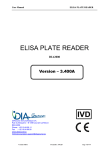
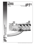
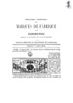
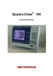
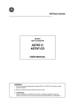
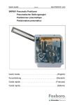
TROUBLESHOOTING THE QUICKCHILLER
The QuickChiller is a stand alone, high capacity refrigeration system used to rapidly and uniformly lower
the temperature of a hot food product through the “chill danger zone.” There are five Quickchiller models
consisting of the QC3, QC20, QC40, QC50, and QC100. All models share the same basic electrical and
electronic components.
ELECTRICAL INSTALLATION
Basic installation must be made on a level, load-bearing surface and must have a drain available for
condensate. The electrical requirements are either 208VAC or 240VAC single-phase. All units are shipped in
the 240 VAC default setting. THE SUPPLY VOLTAGE MUST BE VERIFIED BEFORE HOOKUP.
If the supply voltage is 218 to 245 VAC, no changes are needed. If the supply voltage is less than 218 VAC
the leads of the transformer must be changed. Locate and remove the transformer orange lead from the
transformer to the terminal block. Remove the wire nut from the transformer red lead and install it on the
terminal block in the same location from which the
orange wire was removed. Install the wire nut on the
Figure 1
orange wire and secure it. Once again verify the power
supply matches the transformer setup. Once the power
supply is connected, the unit circuit breaker, which is
®
mounted on the relay board enclosure, must be
switched ON .
MENU SCREEN
™
MICROPROCESSOR CONTROL
The Alto-Shaam Quickchiller has a microprocessor
control panel, which utilizes a menu screen to guide
the operator through all operation mode sequences.
The main menu screen should appear in the control
display (Figure 1). If the Main Menu screen does not
appear, the control display will show “SYSTEM
INITIALIZED” and an audible alarm will sound for 30
to 60 seconds. THE QUICKCHILLER SHOULD BE
LEFT IN THIS CONDITION FOR A PERIOD OF
TWO (2) MINUTES.
After waiting 2 minutes, turn the Quickchiller
circuit breaker OFF for 30 seconds. Turn the
Quickchiller circuit breaker back ON and the Main
Menu screen will appear on the display.
CONTROL
KEYBOARD
QUICK
REFERENCE
OPERATION
GUIDE
SERIAL PRINTER PORT
QUICKCHILLER SET-UP SCREEN
From the Main Menu screen, press and hold the “1” key
for 5 seconds. The Software Version screen (Figure 2)
will appear. NOTE: YOU MUST VERIFY THAT THE
QUICKCHILLER IS PROGRAMMED TO THE
SPECIFIC UNIT MODEL NUMBER. After verifying
the programmed model number is correct, press the
“D” key to return to the Main Menu screen.
Figure 2
QUICKCHILLER .
QC-50
SOFTWARE
.
Vers:
1/17/01
VER.
01/17/01
3.20
08:43
08:43:01AM
1.
QUICKCHILLER SET-UP
Figure 3
PA S S W O R D E N T RY S C R E E N
Since all Quickchillers use the same microprocessor, they
must be configured for each specific model. The set-up is
Q-CHILLER CONFIGURE
completed at the factory, however, if the unit is unplugged for
more than 14 days, the microprocessor will lose the factory set
memory and revert back to a default setup. The default is
PA S S W O R D : 5588744
always specific to the model QC 50.
The Main Menu screen must appear on the control
Figure 4
display. To access the Password screen, press and hold the
PA
S
S
W
O
R
D DENIED SCREEN
“0” key on the key board for 5 seconds. When the Password
screen is in view, enter the password 5588744 using the
control keyboard (Figure 3).
After entering the password on the Password screen, press
AC C E S S D E N I E D
the “D” key on the keyboard to access the User Setting screen.
Press and hold the "1" button on the keyboard for a period of five (5)
seconds. The Software Version screen will appear. The Quickchiller
model number must appear.
Press and hold the "1" button on the keyboard for a period of five (5) seconds. The Software Version screen will
appear. The Quickchiller model number must appear.
If the model number does not appear, press and hold zero (0) button again until Password Entry screen appears.
Enter password 16021892 and press "D" button to access Set-up Menu Screen. Select option "C" and set correct chiller
model number using the "C" button. Following entry, press "D", and press "D" again to return to Main Menu screen.
NOTE: If the wrong password number is entered in error, “ACCESS DENIED” (Figure 4) will appear in the
display, an alarm will sound for 10 seconds, and the Main Menu screen will reappear. If this
situation occurs, press and hold the “0” key for 5 seconds and reenter the correct password.
SETTING TIME, DATE & OPTIONS
When the User Setting screen (Figure 5) appears on the
control display, push the “B” key on the keyboard to access
the time and date screen (Figure 6). The time and date are
very important particularly if a printer is used since
incorrect time and date settings will impact the printout.
Figure 5
USER SETTING MENU SCREEN
S e t Po i n t s . . . . . . . . . . . . A
Time and Date . . . . . . . . . B
Miscellaneous . . . . . . . . . C
Exit . . . . . . . . . . . . . . . . D
NOTE: TIME MUST BE ENTERED AS 24 HOUR,
MILITARY TIME (HH:MM:SS).
After the time and date have been set, press the “C” key
to return to the User Setting screen. After the User Setting
screen appears, press the “C” (Miscellaneous) key to change
the following options. Press “A” to scroll to the next screen.
Figure 6
T I M E A N D D AT E S C R E E N
Enter Time and Date
01/17/01
A=Left
08:33:48
C=Accept
B=Right
D=Cancel
TEMPERATURE UNITS: Allows the user to choose
between Celsius and Fahrenheit.
KEYBOARD BUZZER: Allows the user to turn tone sound ON or OFF .
AUTOMATIC DEFROST: Allows the user to turn the Auto-Defrost ON or OFF .
DEFROST TIME: Allows the user to set the maximum minutes for the defrost cycle.
NOTE: DEFAULT IS SET FOR 20 MINUTES
AFTER ALL OPTIONS HAVE BEEN SELECTED, PRESS “D” TO EXIT AND RETURN TO THE USER SETTING SCREEN.
SETTING SET POINTS
From the user screen, press the”A” (Set Point) key to access the Numeric Setting screen (Figure 7). All
set points are shown in Celsius and can only be changed within an allowable range. Any value entered
outside of this range will result in a warning buzzer and the value must be reentered. To reset any set point
to the factory default, push the “CE” key to show the default values for each set point and then key in the
2.
correct setting. Temperatures that require a negative number can
be entered by using the minus key ”-“ on the keyboard. To exit,
press the “D” key and return to the User Setting screen. To
return to the Main Menu screen press the “D” key again.
NOTE: THE SET POINT CONFIGURATIONS HAVE BEEN
ESTABLISHED AFTER EXTENSIVE TESTING.
CHANGING THE SET POINTS MAY SERIOUSLY
AFFECT THE OPERATION OF THE QUICKCHILLER.
The factory default set points for all the Quickchillers are
listed in the appendix at the end of the Trouble Shooting Guide.
Figure 7
USER SETTING MENU SCREEN
S e t Po i n t s . . . . . . . . . . . . A
Time and Date . . . . . . . . . B
Miscellaneous . . . . . . . . . C
Exit . . . . . . . . . . . . . . . . D
CPU BOARD
The CPU board is the microprocessor for the Quickchiller. It processes and controls all input from the
product probes, air temperature sensor, the coil 1 and coil 2 RTD sensors, the LCD driver board, the keyboard
touch pad, and the printer. The microprocessor has a battery that will allow the CPU board to hold a program
for up to 14 days in the event of a power failure. A ribbon cable allows the relay board to communicate with
the CPU board.
The CPU reset and power LED are located at the bottom part of the board (Figure 8).
NOTE: THERE IS AN RTD SENSOR BUILT INTO A CHIP TO MONITOR TEMPERATURE IN THE CPU
ENCLOSURE. IF THE TEMPERATURE IN THE ENCLOSURE EXCEEDS 115 DEGREES F. (46°C), THE
CONTROL WILL FAIL. THERE ARE NO SERVICEABLE PARTS ON THE CPU BOARD.
Figure 8
AIR SENSOR
COIL 1 & COIL 2
RTD SENSORS
24VAC (J12)
WRITE
PROTECT SWITCH
RELAY/CPU
RIBBON CABLE
PRODUCT PROBE
1, 2, 3
5VDC
PFI PIN
P12 TRIM-POT
DISPLAY RIBBON
CABLE
POWER LED
BATTERY
SWITCH
KEYBOARD
RIBBON
DIP
SWITCHES
CPU
RESET
PRINTER SERIAL
PORT CONNECTOR
3.
TROUBLE SHOOTING THE CPU BOARD
If the CPU board is suspected as the problem, open the locked CPU access door and verify the green
power LED is illuminated. If the LED is not illuminated and there is 24VAC on the J12 connector across L1
and L2, the CPU board is defective and must be replaced (Figure 8). Also check for 12VAC from L1 to COM
and from L2 to COM. If there is no voltage or 1/2 voltage present, check for 24VAC across the 2 outside
terminals at the J17 connector on the relay board (Figure 9). If there is 24VAC on the J17 connector, the
wiring from the relay board to the CPU board is defective and needs to be replaced.
Figure 9
24VAC
12VAC FROM
L 1 TO GROUND
AND
L 2 TO GROUND
12VAC FROM
L 1 TO GROUND
AND
L 2 TO GROUND
POWER LED
24VAC
5VDC
If there is no 24VAC across L1 and L2 on the J17 plug, check the F16
and F17 1 AMP fuses. If the fuses are good and there is no 24VAC present
at J18 connector or if the green power LED on the relay board is not
illuminated, the circuit breaker switch is tripped or defective. If the circuit
breaker switch is turned ON and appears good, check for line voltage
through the filter at the terminal block mounted at the top of the relay
board enclosure. If there is line voltage at the terminal block, the
transformer is defective and needs to be replaced.
Figure 10
If the LCD display is blank and the circuit breaker switch is turned ON ,
check that the LCD display ribbon cable is not cut or damaged. If it is
connected properly to the LCD driver board and the pins on the board are
clean, check to make certain it is plugged into the J13 connector and seated
properly. If the above checks out good, power down the control by turning
the circuit breaker switch OFF . Inspect chip-set U15, U11 and U10 to make
certain they are seated properly. Turn the circuit breaker switch ON and
check the display. If there is still no display, check to make certain the
power failure threshold is set to between 1.70 and 1.85VDC.
To set the power failure threshold, locate the P12 trim-pot at the lower
left-hand portion of the CPU board (Figure 10). Using a multi-meter set to
the DC volts scale, place the red lead onto pin connector PFI and the black
lead onto the metal board retaining nut. Adjust the trim-pot P12 until the
voltage reading is between 1.70 and 1.85VDC.
4.
ADJUST TRIM-POT TO
RAISE THRESHOLD
TO 1.70 - 1.85 VDC (P12)
PFI
RELAY BOARD
The relay board (Figure 11) is mounted in a metal enclosure with a metal or lexan cover over it. For the
QC-3 it is located behind the front grille, mounted to the left of the compressor and can be slid out for
servicing. For the QC-20 it is located behind the CPU enclosure, laying flat and can be slid out for servicing.
For the QC-40 it is located behind the lower grille, mounted to the left of the compressors and can be slid
out for servicing. For the QC-50 it is located behind the upper grille, to the left of the compressors and can
be accessed by removing the metal cover. For the QC-100 it is located inside the locked CPU enclosure at the
top of the enclosure.
Figure 11
REFRIGERANT
SOLENOID
DEFROST
HEATERS
LEFT
COMPRESSORS
FAN FUSES
RIGHT
COMPRESSOR
FUSE
EVAPORATOR FANS
LEFT
EVAPORATOR FANS
RIGHT
HEATER DEFROST
RELAYS 14VDC
DEFROST
HEATER
FUSES
SOLENOID
FUSES
POWER LED
RIBBON CABLE
CONNECTOR
BEEPER
DOOR
SWITCH
5DVC
TO CPU BOARD
24VAC
CPU
POWER FUSES
TO CPU BOARD
24VAC
FROM
TRANSFORMER
The relay board has 6 (F1-F6) 2A fuses to protect the fans. There are 6 (F7-F12) 4A fuses to protect the
defrost heaters in all Quickchillers except the QC-40 which uses 6.3 Amp fuses. All units use 2 (F13-F14)
300MA fuses to protect the refrigerant solenoids and 1 (F14) 250MA fuse to protect the compressor relays. The
2 (F16-F17) 1A fuses protect the 24 VAC power to the CPU board.
5.
There are 16 LED’s on the relay board (Figure 12) that illuminate when that function of the board is
energized and can be used in diagnostics.
NOTE: THE ONLY REPLACEMENT PARTS ON THE RELAY BOARD ARE THE FUSES AND THE DEFROST
HEATER RELAYS.
Figure 12
CPU BOARD POWER LED (J17)
FAN RELAY LED'S
14VDC RELAY VOLTAGE LED
(REL3, REL4, REL5)
5VDC CPU BOARD POWER LED (J16)
DEFROST HEATER
RELAY LED'S
CPU IS POWERED & CONNECTED BUT
NOT RUNNING A PROGRAM
CPU DIAGNOSTIC SOFTWARE LED
DOOR OPEN/CLOSED LED
REFRIGERANT
SOLENOID RELAY
LED'S
COMPRESSOR
RELAY LED
CPU IS CONNECTED, POWERED, &
RUNNING A PROGRAM
BUZZER ON/OFF LED
When the unit is powered up, the door is closed, and the Main Menu screen appears on the control display,
the following LED’s must be illuminated: WDI, +5V, +14V,CPU.
TROUBLE SHOOTING THE RELAY BOARD
If the relay board is suspected as the problem, check to make certain the power LED, located in the lower
right corner, is illuminated. If it is not illuminated, check at the power input connector (J18) for 24VAC across
the 2 outside terminals. If there is 24VAC present and the power LED is not illuminated, the relay board is
defective and must be replaced. If there is no
voltage present, check to make certain the
Figure 13
circuit breaker switch is good and it is turned
ON . If the breaker switch is good, check
power by locating the terminal block in the
upper, right side of the relay board enclosure
and check for line voltage across the two
outside terminals. If the voltage is present,
then the transformer is defective and must be
2A FAN
replaced.
FUSES
The evaporator fans are powered by the
relay board, through the J1 and J2 plugs on
the upper left corner of the relay board
(Figure 13). L 2 is continuously supplied to
the evaporator fan motors and L 1 is switched
by solid state relays, with protection by the
2A fuses (F1-F6). L 2 goes to the fan
SOLID
terminator located on the evaporator suction
STATE
FAN
line, which closes at 30 degrees F (-1 degree C)
RELAYS
and opens at 60 degrees F (16 degrees C).
6.
Even though the fan LED’s are illuminated on the relay board, the
terminator must be satisfied before the fans will operate.
Figure 14
NOTE: IF THE EVAPORATOR COIL 1 OR EVAPORATOR COIL 2 RTD
SENSOR IS DISCONNECTED OR DEFECTIVE, THE FAN LED’S
OR THE EVAPORATOR FANS WILL NOT BE ENERGIZED. THE
RTD CONNECTIONS ARE LOCATED, IN THE LOWER RIGHT
CORNER OF THE CPU BOARD AT THE J6 PLUG (FIGURE 14).
Figure 15
4A
DEFROST
HEATER
FUSES
OR
6-3A
FUSES
FOR
QC-40
MODEL
DEFROST
HEATER
RELAYS
L1
L2
L1
L2
L2 IS ALWAYS
ENERGIZED. L1
IS SUPPLIED BY
THE SOLID STATE
RELAYS TO
PROPER FAN
DEPENDING ON
MODEL NUMBER.
COIL 1
RTD SENSOR
LEADS
COIL 2
RTD SENSOR
LEADS
The defrost heaters are powered by the
relay board, through the J3 and J4 plugs on
the upper middle of the relay board (Figure
15). L 2 is continuously supplied to the
defrost heaters and L 1 is switched by the "ice
cube" relays with protection by the 4A fuses
or 6.3A fuses in the model QC-40 (F7-F12).
L 2 goes to the defrost terminator, located on
a plate above the evaporator, and which
closes at 30 degrees F (-1 degree C) and
opens at 60 degrees F (16 degrees C). The
evaporator fan(s), solenoid(s) or
compressor(s) are not energized when the
unit is in either one of the defrost modes.
NOTE: IF THERE IS NO POWER THROUGH ANY OF THE RELAYS, INITIALLY ENSURE THE RELAY PINS
AND SOCKETS ARE CLEAN AND PROPERLY SEATED. THERE IS A RETAINING STRAP ACROSS
THE TOP OF THE RELAY TO KEEP IT FROM VIBRATING LOOSE IN THE SOCKET. TO TEST THE
RELAY COIL, USE A MULTI-METER SET TO THE OHMS SCALE. TEST ACROSS THE 2 VERTICAL
PINS. THE RESISTANCE READING SHOULD BE APPROXIMATELY 150 OHMS RESISTANCE.
The Manual Defrost time is factory pre-set for 20 minutes. When the unit is in the Manual Defrost mode, the
control will time down and the heater(s) will be activated until the defrost
terminator senses 60 degrees F (16 degrees C). At that time, the defrost
Figure 16
L2 LEFT
heater(s) will be de-energized and the control will finish timing down to zero.
L2 RIGHT
The Control Display will read "Defrost Finished." Push the “D” key to return
L2 IS ALWAYS
L1
to the Main Menu screen. In the Automatic Defrost mode the unit will go
ENERGIZED. L1 IS
into defrost whenever the evaporator fans are running for at least a 6-hour
SUPPLIED BY THE
cumulative period of time, the unit has been in the hold mode for at least 15
SOLID STATE
RELAY TO THE
minutes, and the internal cavity temperature is not above 35 degrees F (1,7
PROPER SOLENOID.
degrees Celsius. When in the Automatic Defrost mode, the unit will go into
defrost, after the above conditions are met until the defrost terminators reach
60 degrees F (16 degrees C). At that time the Control Display will read
"Defrost Finished" and the unit will continue in the hold cycle.
The refrigerant solenoid valves are powered by the relay board through the
J5 plug which is located on the upper right corner of the relay board (Figure
SOLID STATE
16). L 2 is continuously supplied to the solenoid coil and L 1 is switched by the
RELAYS
solid state relays on the relay board, with protection by the 300MA fuses (F13F14). If there is 208/240VAC supplied to the solenoid coils and the solenoid
valve is not opening, the coil may be defective. To check for a defective coil,
disconnect the leads to the coil. Using a multimeter set to the OMH’s scale,
measure between the 2 terminals. There should be 780 OHM’s resistance.
300MA
NOTE: DO NOT APPLY POWER TO A COIL THAT IS NOT MOUNTED
TO THE SOLENOID VALVE. THIS ACTION WILL CAUSE THE
COIL TO MELT.
FUSES
7.
The condenser unit(s) solid state relay(s) are powered by the relay
board through the J6 plug located on the upper right corner of the relay
board (Figure 17). L 2 is continuously supplied to the solid state condenser
relay(s) and L 1 is switched by the solid state relay on the relay board with
protection by the 250MA fuse (F15).
During either Chill mode or the Holding mode, L 1 and L 2 is
continuously supplied both to and through the solid state relay on the relay
board, to and through the condenser solid state relay(s), and to the pressure
switch(s) and the compressor(s). Both the solid state relay on the relay
board and the solid state relay(s) for the condenser are powered at all times
and the condensers are cycled by the probes. Line voltage (both L 1 and L 2 )
to the condensing units is protected by the SC15 or SC 20 fuses located in
the relay board enclosure. When the probe temperatures are satisfied, the
relay board de-energizes the solenoid valve(s) which causes the
compressor(s) to pump-down into a vacuum. When the pressure on the
suction line drops to 2PSIG, the pressure switch will open and disconnect
the voltage on L 1 which causes the condenser to shut OFF . When the
probe(s) call for cooling, the relay board re-energizes the solenoid coil(s)
causing the low side pressure to rise. When the pressure increases to 18
PSIG, the pressure switch will close which will supply voltage on L 1 and
turn the condensing unit ON .
Figure 17
L1 SUPPLY
VOLTAGE TO
SOLID
STATE
RELAY
ON
RELAY
BOARD.
L1 SUPPLY
VOLTAGE
FROM SOLID
STATE RELAY
ON RELAY
BOARD TO
CONDENSER
SOLID STATE
RELAY(S).
250MA
FUSE
SOLID
STATE
RELAY
NOTE: IF THE SOLENOID COIL DOES NOT CLOSE, THE RELAY BOARD SOLENOID COIL LED IS NOT
ILLUMINATED AND THERE IS NO POWER TO THE SOLENOID COIL, A VARISTOR MUST BE
INSTALLED ACROSS L 1 AND THE RIGHT AND/OR LEFT SOLENOID COIL CONNECTION ON
PLUG J5 (FIGURE 16).
PRESSURE SWITCH
The pressure switch is opened and closed by means of a capillary tube connected to the suction line
which applies pressure on a diaphragm to open and close the switch. The cut-out setting is 2PSIG and the
cut-in setting is 18PSIG.
NOTE: IF THERE IS A LEAK IN THE REFRIGERATION SYSTEM, THE CONDENSER WILL NOT TURN ON.
ON
TO TEST THE CONDENSER, JUMP-OUT THE PRESSURE SWITCH. IF THE CONDENSER TESTS
GOOD, REMOVE THE JUMPER, LOCATE AND REPAIR THE LEAK, AND RECHARGE THE SYSTEM.
8.
Figure 18
EVAPORATOR COIL AND SENSOR LOCATION (MODELS QC3 AND QC20)
COIL SENSOR
DEFROST
TERMINATOR
PRODUCT
PROBE
FAN
TERMINATOR
TEMPERATURE
EXPANSION VALVE
AIR TEMPERATURE
SENSOR
EVAPORATOR FAN
CONNECTOR
DEFROST
HEATER
9.
Figure 19
EVAPORATOR COIL AND SENSOR LOCATION (MODEL QC 40)
DEFROST
HEATER
TEMPERATURE
EXPANSION
VALVE
COIL RTD
SENSORS
DEFROST
TERMINATOR
FAN
TERMINATOR
The QC40 has a split coil evaporator under the floor of the cabinet and uses 3 evaporator fans.
10.
Figure 20
EVAPORATOR COIL AND SENSOR LOCATION (QC 50 AND QC100)
TEMPERATURE
EXPANSION
VALVE
DEFROST HEATER
TERMINATOR
COIL
SENSOR
D
FAN
TERMINATOR
EF
RO
ST
H
TE
EA
R
The QC50 has 2 evaporators on the left side of the cabinet along with an evaporator in the ceiling of the
cabinet. There are a total of 6 evaporator fans on the left side wall and 2 evaporator fans in the ceiling. The
QC100 has 2 evaporators on each side of the cabinet and uses a total of 12 evaporator fans.
NOTE: THE QC50 HAS 3 EVAPORATOR FANS THAT ROTATE IN A CLOCKWISE DIRECTION AND 3
EVAPORATOR FANS THAT ROTATE IN A COUNTER-CLOCKWISE DIRECTION. THE QC100 HAS 6
EVAPORATOR FANS THAT ROTATE CLOCKWISE AND 6 EVAPORATOR FANS THAT ROTATE
COUNTER-CLOCKWISE.
11.
TROUBLE SHOOTING EVAPORATOR COMPONENTS
FAN TERMINATOR
The fan terminator is located on the suction line and is
covered by cork tape. The terminator is closed at 30
degrees F (-1 C) and opens at 60 degrees F (16 C). If the
terminator is suspected as the problem, the evaporator
coil must be cooled to 30 degrees F (-1 C). This can be
verified by placing the unit in the Auto Chill Mode
followed by a 5 minute waiting period. After 5 minutes,
push and hold the 2 key on the keyboard for 5 seconds.
The RTD Temperature Screen should appear (Figure 21).
Figure 21
UP:
72.0
COL1
23.4
MID:
72.0
COL2
22.4
LOW:
73.4
CPU:
72.7
AIR:
74.4
(F)
EXIT=D
Observe the temperature of COL 1 and COL 2. If the temperature of the coils is under 30 degrees F (-1 C)
and the fan(s) are not turning, the fuses, the terminator, the wire from the terminator to the fan, or the fan
motor may be defective. Disconnect the plug from the fan and with a multimeter set to the VAC scale, check
across the 2 outside pins. There should be 208/240VAC. If the correct voltage is present, turn OFF the power
and plug the fan in. Turn the power ON . If the fan does not run, the fan motor is defective and needs to be
replaced. If there is no voltage present, disconnect the wires from the terminator and with a multimeter set to
the OHMS scale, check for continuity through the terminator. If there is no continuity, the terminator is
defective and needs to be replaced.
NOTE: IN AN EMERGENCY, THE UNIT CAN BE OPERATED WITH THE FAN TERMINATOR BYPASSED,
BUT ONLY UNTIL A NEW PART IS RECEIVED AND INSTALLED. AT NO TIME SHOULD
BYPASSING THE TERMINATOR BE A PERMANENT SOLUTION.
DEFROST TERMINATOR
The defrost terminator is located on a plate, usually above the evaporator coil. The terminator closes at 30
degrees F (-1 C) and opens at 60 degrees F (16 C). If the terminator is suspected as the problem, verify the coil
temperature is at 30 degrees F (-1 C) by accessing the RTD Temperature Screen (Figure 21). If the coil
temperature is 30 degrees (-1 C), turn the unit OFF . Access the 2 evaporator heater leads and disconnect. With
a multimeter set to the VAC scale and connected to the heater leads, place the unit into defrost. There should
be 208/240VAC present. If not, turn the unit OFF , and disconnect the defrost terminator leads. With a
multimeter set to the OHMS scale, test for continuity through the terminator. If there is no continuity, the
terminator is defective and needs to be replaced. If the defrost heater is suspect, disconnect the heater leads
and with a multimeter set to the OHMS scale, test for continuity through the heater.
RTD COIL SENSOR, PRODUCT PROBES, AND AIR SENSOR
The RTD coil sensor, located on the suction line and covered by black cork tape, can be tested by
placing the sensor in an ice water bath. With a multimeter set to the OHMS scale, there should be 100
OHMS resistance at 32 degrees F (0 C). The product probe and air temperature sensor should be tested in
the same manner.
NOTE: WHEN REPLACING ANY OF THE SENSORS OR PRODUCT PROBES, BE CERTAIN TO CONNECT
THEM TO THE CORRECT PLUGS ON THE CPU BOARD.
12.
DOOR SWITCH
There are up to three types of door switches that were installed on the
Quickchillers. The oldest type was installed in the bottom of the top hinge
Figure 22
(Figure 22). When the door is opened, the hinge post ramped-up and opened the
contacts of the door switch. When the door is closed, the hinge post rampeddown and closed the contacts of the door switch. This type of door switch can be
easily identified since the top hinge is longer than the bottom hinge.
The next style door switch
Figure 23
uses a bullet magnet screwed on
the top of the door with the door
switch under the top mullion
DOOR
SWITCH
strip (Figure 23). To test and
replace, remove the screws
holding the mullion strip in place
DOOR
MAGNET
INTERLOCK
SWITCH
and pull down the strip. The switch can be removed and
replaced, and the mullion strip reinstalled.
The newest style door switch uses the
same magnet and interlock switch as the
Figure 24
Combitherm (Figure 24). The magnet is
screwed to the side of the door across from
the door latch. The interlock switch is
mounted inside the door latch and can be
replaced by removing the four screws holding
the door latch to the frame. Cut the 2 red
wires leaving enough wire to make the splice
and remove the nut holding the switch to the
latch. Install the new switch into the latch
using butt connectors to connect the wires to
the 2 red wires of the unit. Reinstall the latch
and test for proper operation.
INTERLOCK
SWITCH
DOOR
MAGNET
13.
Figure 25
CONDENSER COMPONENTS
RELAY BOARD
ENCLOSURE
CONDENSATE
DRAIN PAN AND
DRAIN HOSE
RECEIVER
CONDENSER COIL
AND FAN
HIGH SIDE
SERVICE VALVE
SUCTION LINE
SERVICE VALVE
COMPRESSOR
CAPACITORS
FILTER/DRIER
SIGHT PORT
SOLENOID
VALVE
OPERATING PRESSURES
(R404A)
LO
HI
(R22)
LO
HI
14.
20-25 LBS. @ 38 DEGREES F (AMBIENT: 90 DEGREES F)
275-300 LBS.
19-25 LBS. @ 38 DEGREES F (AMBIENT: 90 DEGREES F)
250-275 LBS.
DIAGNOSTIC MENU SCREEN
As an aid for repairing or checking the Quickchiller, a
Figure 26
diagnostic menu allows the technician to independently enable
or disable the solenoids, fans, heaters, and compressors. The
Q-CHILLER CONFIGURE
technician can also view the temperature readings for each of the
RTD coil sensors, air temperature sensor, and the product
PA S S W O R D : 9 1 0 9 5 3 4 0
probes. To access the diagnostic screen from the main menu
screen, press and hold the "0" key for 5 seconds. When the
Password entry screen appears, enter the diagnostic password
91095340 and push the "D" key (Figure 26).
Figure 27
The diagnostic menu screen appears (Figure 27). Check each
function as required by pressing keyboard buttons "0" through
SOLEND
1=HLD
2=CHL
FA N S
3=HLD
4=CHL
H E AT E R
5=HLD
6, 7=CHL
COMPRS
8=ALL
9, 0, D
"9." Press the "D" key to exit the program.
"1" . . . . Open/close the holding compressor solenoid
"2" . . . . Open/close the chilling compressor solenoid
"3" . . . . Toggle holding evaporator fans on/off
"4" . . . . Toggle chilling evaporator fans on/off
"5" . . . . Toggle heaters for holding evaporator on/off
"6" "7" . . Toggle heaters for chilling evaporator on/off
"8" . . . . Toggle compressor power on/off
"9" . . . . Display real-time temperature readings
"0" . . . . Display software version date
"D" . . . Exit program
The temperature of the three food probes are shown as "UP",
Figure 28
"MID", and "LOW." The air probe is "AIR." The probes on the
evaporator coils are identified as "COL1" and "COL2." The
UP:
72.0
COL1: 23.4
temperature inside the CPU enclosure is shown as "CPU."
MID:
72.0
COL2: 22.4
Temperature units are "(F)" for Fahrenheit and "(C)" for Celsius
L OW : 7 3 . 4
(Figure 28).
AIR:
74.4
CPU:
(F)
72.7
EXIT=D
15.
FACTORY SETUP CONFIGURATIONS
QC-3 CONTROL SETTINGS
PRINTER
Printer Interface
Baud Rate
Stop Bits
Printing Delay
Sample Period, min.
Print Grid Spacing
Print Grids
Printer Columns
BUZZERS/TIME-OUTS
Probe Mute Time, sec.
Chill Done Time, sec.
Are-U-Sure Time, sec.
DefrstDone Time, sec.
Probe Mute Buzzer
Chill Done Buzzer
Are-U-Sure Buzzer
Defrost Done Buzzer
HOLDING
Hold Set-point, C
Hold Offset, 0.1C
Hold Low Offset, 0.1C
Hold Med Offset, 0.1C
Hold High Offset. 0.1C
CHILLING
Probe 1 Set-point, C
Probe 2 Set-point, C
Probe 3 Set-point, C
Chill Set-point, C
Chill Offset, 0.1C
ChillLow Offset. 0.1C
ChillMed Offset, 0.1C
ChillHi Offset. 0.1C
DEFROSTING
Automatic Defrost
AutoDefrst Per. 5min
DefrstWarnTime, 10min
Coil1 Defrost End. C
Coil2 Defrost End, C
Defrost Time, min
MISC
Chiller Model
Compressor Mode
Number Compressors
Power Throttle
Temp Cycling
RTD Offset, 0.1C
Power Down Minutes
Temperature Units
Time Format
Fan Cut-in Temp, C
Fan Cut-Out Temp, C
KeyBoard Buzzer
Device Access Number
16.
QC-20 CONTROL SETTINGS
PRINTER
PRINTER
=
Serial
=
4800
=
1 bit
= 40 [40]
= 5 [ 5]
= 5 [ 5]
=
YES
=
[40]
=
=
=
=
=
=
=
=
30
60
20
60
0
1
2
3
[30]
[60]
[20]
[60]
[ 0]
[ 1]
[ 2]
[ 3]
=
=
=
=
=
3
0
6
4
4
[
[
[
[
[
3]
0]
6]
4]
4]
=
=
=
=
=
=
=
=
4
4
4
-6
0
8
8
8
[
[
[
[[
[
[
[
4]
4]
4]
6]
0]
8]
8]
8]
=
=
=
=
=
=
72
60
16
16
20
YES
[72]
[60]
[16]
[16]
[20]
=
QC-3
= CPU CNTR
=
ONE
=
NO
=
YES
= 0 [ 0]
= 1 [ 1]
=
Farhen
HH:MM
=
= 4 [ 4]
= 13 [13]
=
ON
= 49 [49]
Printer Interface
Baud Rate
Stop Bits
Printing Delay
Sample Period, min.
Print Grid Spacing
Print Grids
Printer Columns
BUZZERS/TIME-OUTS
Probe Mute Time, sec.
Chill Done Time, sec.
Are-U-Sure Time, sec.
DefrstDone Time, sec.
Probe Mute Buzzer
Chill Done Buzzer
Are-U-Sure Buzzer
Defrost Done Buzzer
HOLDING
Hold Set-point, C
Hold Offset, 0.1C
Hold Low Offset, 0.1C
Hold Med Offset, 0.1C
Hold High Offset. 0.1C
CHILLING
Probe 1 Set-point, C
Probe 2 Set-point, C
Probe 3 Set-point, C
Chill Set-point, C
Chill Offset, 0.1C
ChillLow Offset. 0.1C
ChillMed Offset, 0.1C
ChillHi Offset. 0.1C
DEFROSTING
Automatic Defrost
AutoDefrst Per. 5min
DefrstWarnTime, 10min
Coil1 Defrost End. C
Coil2 Defrost End, C
Defrost Time, min
MISC
Chiller Model
Compressor Mode
Number Compressors
Power Throttle
Temp Cycling
RTD Offset, 0.1C
Power Down Minutes
Temperature Units
Time Format
Fan Cut-in Temp, C
Fan Cut-Out Temp, C
KeyBoard Buzzer
Device Access Number
QC-40 CONTROL SETTINGS
=
Serial
=
4800
=
1 bit
= 40 [40]
= 5 [ 5]
= 5 [ 5]
=
YES
=
[40]
=
=
=
=
=
=
=
=
30
60
20
60
0
1
2
3
[30]
[60]
[20]
[60]
[ 0]
[ 1]
[ 2]
[ 3]
=
=
=
=
=
3
0
6
4
4
[
[
[
[
[
3]
0]
6]
4]
4]
=
=
=
=
=
=
=
=
4
4
4
-6
0
8
8
8
[
[
[
[[
[
[
[
4]
4]
4]
6]
0]
8]
8]
8]
=
=
=
=
=
=
72
60
16
16
20
YES
[72]
[60]
[16]
[16]
[20]
=
QC-20
= CPU CNTR
=
ONE
=
NO
=
YES
= 0 [ 0]
= 1 [ 1]
=
Farhen
HH:MM
=
= 4 [ 4]
= 13 [13]
=
ON
= 49 [49]
Printer Interface
Baud Rate
Stop Bits
Printing Delay
Sample Period, min.
Print Grid Spacing
Print Grids
Printer Columns
BUZZERS/TIME-OUTS
Probe Mute Time, sec.
Chill Done Time, sec.
Are-U-Sure Time, sec.
DefrstDone Time, sec.
Probe Mute Buzzer
Chill Done Buzzer
Are-U-Sure Buzzer
Defrost Done Buzzer
HOLDING
Hold Set-point, C
Hold Offset, 0.1C
Hold Low Offset, 0.1C
Hold Med Offset, 0.1C
Hold High Offset. 0.1C
CHILLING
Probe 1 Set-point, C
Probe 2 Set-point, C
Probe 3 Set-point, C
Chill Set-point, C
Chill Offset, 0.1C
ChillLow Offset. 0.1C
ChillMed Offset, 0.1C
ChillHi Offset. 0.1C
DEFROSTING
Automatic Defrost
AutoDefrst Per. 5min
DefrstWarnTime, 10min
Coil1 Defrost End. C
Coil2 Defrost End, C
Defrost Time, min
MISC
Chiller Model
Compressor Mode
Number Compressors
Power Throttle
Temp Cycling
RTD Offset, 0.1C
Power Down Minutes
Temperature Units
Time Format
Fan Cut-in Temp, C
Fan Cut-Out Temp, C
KeyBoard Buzzer
Device Access Number
=
Serial
=
4800
=
1 bit
= 40 [40]
= 5 [ 5]
= 5 [ 5]
=
YES
=
[40]
=
=
=
=
=
=
=
=
30
60
20
60
0
1
2
3
=
=
=
=
=
3
0
6
4
4
[30]
[60]
[20]
[60]
[ 0]
[ 1]
[ 2]
[ 3]
[
[
[
[
[
3]
0]
6]
4]
4]
= 4 [ 4]
= 4 [ 4]
= 4 [ 4]
= -10 [-10]
= 0 [ 0]
= 8 [ 8]
= 8 [ 8]
= 8 [ 8]
=
=
=
=
=
=
72
60
16
16
20
YES
[72]
[60]
[16]
[16]
[20]
=
QC-40
= CPU CNTR
=
TWO
=
YES
=
YES
= 0 [ 0]
= 1 [ 1]
=
Farhen
=
HH:MM
= 4 [ 4]
= 13 [13]
=
ON
= 49 [49]
FACTORY SETUP CONFIGURATIONS
QC-50 CONTROL SETTINGS
PRINTER
QC-100 CONTROL SETTINGS
PRINTER
Printer Interface
=
Serial
Printer Interface
=
Serial
Baud Rate
=
4800
Baud Rate
=
4800
Stop Bits
=
1 bit
Stop Bits
=
1 bit
= 40 [40]
Printing Delay
Printing Delay
= 40 [40]
Sample Period, min.
=
5 [ 5]
Sample Period, min.
=
5 [ 5]
Print Grid Spacing
=
5 [ 5]
Print Grid Spacing
=
5 [ 5]
Print Grids
=
YES
Print Grids
=
YES
Printer Columns
=
[40]
Printer Columns
=
[40]
BUZZERS/TIME-OUTS
BUZZERS/TIME-OUTS
Probe Mute Time, sec.
= 30 [30]
Probe Mute Time, sec.
= 30 [30]
Chill Done Time, sec.
= 60 [60]
Chill Done Time, sec.
= 60 [60]
Are-U-Sure Time, sec.
= 20 [20]
Are-U-Sure Time, sec.
= 20 [20]
DefrstDone Time, sec.
= 60 [60]
DefrstDone Time, sec.
= 60 [60]
Probe Mute Buzzer
=
0 [ 0]
Probe Mute Buzzer
=
0 [ 0]
Chill Done Buzzer
=
1 [ 1]
Chill Done Buzzer
=
1 [ 1]
Are-U-Sure Buzzer
=
2 [ 2]
Are-U-Sure Buzzer
=
2 [ 2]
Defrost Done Buzzer
=
3 [ 3]
Defrost Done Buzzer
=
3 [ 3]
Hold Set-point, C
=
3 [ 3]
Hold Set-point, C
=
3 [ 3]
Hold Offset, 0.1C
=
0 [ 0]
Hold Offset, 0.1C
=
0 [ 0]
6 [ 6]
HOLDING
HOLDING
Hold Low Offset, 0.1C
=
6 [ 6]
Hold Low Offset, 0.1C
=
Hold Med Offset, 0.1C
=
4 [ 4]
Hold Med Offset, 0.1C
=
4 [ 4]
Hold High Offset. 0.1C
=
4 [ 4]
Hold High Offset. 0.1C
=
4 [ 4]
Probe 1 Set-point, C
=
4 [ 4]
Probe 1 Set-point, C
=
4 [ 4]
Probe 2 Set-point, C
=
4 [ 4]
Probe 2 Set-point, C
=
4 [ 4]
Probe 3 Set-point, C
=
4 [ 4]
Probe 3 Set-point, C
=
4 [ 4]
Chill Set-point, C
=
-6 [- 6]
Chill Set-point, C
=
-6 [- 6]
CHILLING
CHILLING
Chill Offset, 0.1C
=
0 [ 0]
Chill Offset, 0.1C
=
0 [ 0]
ChillLow Offset. 0.1C
=
8 [ 8]
ChillLow Offset. 0.1C
=
8 [ 8]
ChillMed Offset, 0.1C
=
8 [ 8]
ChillMed Offset, 0.1C
=
8 [ 8]
ChillHi Offset. 0.1C
=
8 [ 8]
ChillHi Offset. 0.1C
=
8 [ 8]
=
YES
DEFROSTING
DEFROSTING
Automatic Defrost
YES
Automatic Defrost
= 72 [72]
AutoDefrst Per. 5min
DefrstWarnTime, 10min
= 60 [60]
DefrstWarnTime, 10min
= 60 [60]
Coil1 Defrost End. C
= 16 [16]
Coil1 Defrost End. C
= 16 [16]
Coil2 Defrost End, C
= 16 [16]
Coil2 Defrost End, C
= 16 [16]
Defrost Time, min
= 20 [20]
Defrost Time, min
= 20 [20]
AutoDefrst Per. 5min
=
MISC
= 72 [72]
MISC
Chiller Model
Compressor Mode
QC-50
Chiller Model
= CPU CNTR
=
Compressor Mode
=
QC-100
= CPU CNTR
Number Compressors
=
TWO
Number Compressors
=
Power Throttle
=
YES
Power Throttle
=
YES
Temp Cycling
=
YES
Temp Cycling
=
YES
TWO
RTD Offset, 0.1C
=
0 [ 0]
RTD Offset, 0.1C
=
0 [ 0]
Power Down Minutes
=
1 [ 1]
Power Down Minutes
=
1 [ 1]
Temperature Units
=
Farhen
Temperature Units
=
Time Format
=
HH:MM
Time Format
=
Fan Cut-in Temp, C
=
4 [ 4]
Fan Cut-in Temp, C
=
= 13 [13]
Fan Cut-Out Temp, C
Fan Cut-Out Temp, C
KeyBoard Buzzer
Device Access Number
=
ON
KeyBoard Buzzer
= 49 [49]
Device Access Number
Farhen
HH:MM
4 [ 4]
= 13 [13]
=
ON
= 49 [49]
17.
SERVICE NOTES
18.
COOK/HOLD/SERVE SYSTEMS
PHONE: (262)251-3800 (800)558-8744 U . S . A ./ CANADA
●
Ken Kreuscher, Service Manager
● Mike
Hlavenka, Service Support Tech
● EXTENSION
6425
● EXTENSION
8501
SERVICE DEPARTMENT FAX: (262)251-1565 (800)329-8744 U . S . A .
W164 N9221 Water Street
PRINTED IN U.S.A.
●
P.O. Box 450
●
Menomonee Falls, Wisconsin 53052-0450
www.alto-shaam.com
●
U.S.A.
#8421 • 6/01