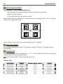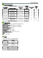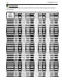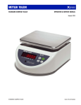
1
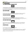
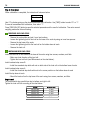
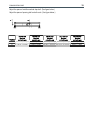
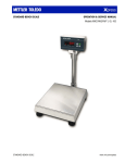
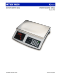
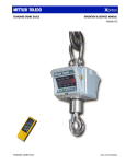
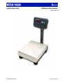
ECONOMY BENCH SCALE
OPERATION & SERVICE MANUAL
Models XBL-XID
ECONOMY BENCH SCALE
www.mt.com/xpress
2
ECONOMY BENCH SCALE
ABOUT THIS MANUAL AND MT XPRESS
Thank you for purchasing an MT Xpress product.
All of our equipment is assembled and packed with great care. If you should find any incorrect item, please
contact your Xpress dealer immediately.
MT Xpress products are Weights & Measures approved precision weighing instruments. However, you may
want to obtain official certification through your supplier or local Weights & Measures office.
This MT Xpress product was developed, produced, and tested in a METTLER TOLEDO facility that has been
audited and registered according to international ISO 9001 quality standards and ISO 14000 environment
control program. Properly used and maintained, this product will provide years of accurate weighing.
Handle it as you would any piece of fine electronic equipment.
Please READ this manual BEFORE operating or servicing this equipment. Follow the instructions carefully
and save this manual for future reference.
We at MT Xpress want to make sure you received the product you expected. It is important to us that you
are satisfied with your purchase. If there is anything we can help you with, or if you are not satisfied with
either your product or the services received from the Xpress representative, let us know.
How can you reach us?
XPRESS CUSTOMER CARE CENTER, USA
24/7 Information and Support:
www.mt.com/xpress
[email protected]
8 AM to 8 PM EST
Toll Free: 1-866-MTXPRESS
Xpress
Mettler-Toledo, Inc.
60 Collegeview
Westerville, OH 43081
ECONOMY BENCH SCALE
FCC Approval
This device complies with part 15 of the FCC Rules. Operation is subject to the following two
conditions: (1) this device may not cause harmful interference, and (2) this device must accept
any interference received, including interference that may cause undesired operation.
3
4
ECONOMY BENCH SCALE
CONTENTS
PREPARING THE SCALE FOR USE ....................................................................................................
UNPACKING AND ASSEMBLY................................................................................................ 5
POWERING UP THE INDICATOR ............................................................................................ 6
YOUR XPRESS SCALE AT A GLANCE ............................................................................................... 7
DISPLAY ............................................................................................................................ 7
KEYPAD............................................................................................................................. 7
CURSORS (LED) ................................................................................................................. 7
OPERATING YOUR SCALE ...............................................................................................................
STRAIGHT WEIGHING .......................................................................................................... 8
TARE FUNCTION ................................................................................................................. 8
POWERING UP AND SELF-CHECKING .................................................................................... 8
SPECIAL MODES – SETUP MODE ................................................................................................... 9
ACCESSING SETUP MODE .................................................................................................... 9
CLEANING & MAINTAINING YOUR SCALE...........................................................................................
CLEANING AND REGULAR MAINTENANCE............................................................................. 10
BATTERY CHECK............................................................................................................... 10
BATTERY REPLACEMENT.................................................................................................... 11
SERVICING YOUR SCALE ................................................................................................................
ACCESSING THE SERVICE MODE......................................................................................... 12
REMOVING OLD LOAD CELLS ............................................................................................. 14
INSTALLING NEW LOAD CELLS ........................................................................................... 14
SHIFT TEST AND ADJUSTMENT ........................................................................................... 16
SETUP SCALE CAPACITY .................................................................................................... 16
DEFLECTION TEST............................................................................................................. 16
APPENDIX....................................................................................................................................
TROUBLESHOOTING .......................................................................................................... 17
ERROR MESSAGES............................................................................................................ 17
CORRECTIVE STEPS .......................................................................................................... 17
MODEL SPECIFICATIONS.................................................................................................... 18
TECHNICAL DATA .............................................................................................................. 18
WIRING ........................................................................................................................... 18
GEO VALUE TABLE ............................................................................................................ 19
PHYSICAL DIMENSIONS ..................................................................................................... 20
5
ECONOMY BENCH SCALE
PREPARING THE SCALE FOR USE
UNPACKING AND ASSEMBLY
Thank you for purchasing an MT Xpress product. Please inspect the package immediately upon receipt. If
the box is damaged, check for internal damage and file a freight claim with the carrier if necessary. If the
container is undamaged, open the box, remove the scale and place it on a solid, flat surface. Please keep
the packing material and shipping insert in case you need to return the scale to an MT Xpress
representative.
Package contents for all MT Xpress Economy Bench Scale units include:
Product
Documents
− Xpress Economy Bench scale
− Quick Start Guide
− Xpress Column indicator
− Installation Instructions
− AC-DC power adapter
− Accessory bag (including 4 socket
head screws, 4 flat washers, 4
spring washers, 1 cable clamp, 1
cable protective baffle, 1 Allen key, 1
seal screws, 1 lead seal wire, 1
lead, “kg” sticker)
1. Open the box and take out the scale. Remove the packing
material from each side of the scale. Set the unit on a sturdy
workplace.
2. Attach the column bracket beneath the bottom scale frame by
tightening the four socket head screws.
CD-ROM
− Operation & Service Manual
6
ECONOMY BENCH SCALE
3. Coil the excess load cell cable and insert it into the column. A
small length of tape applied to the ends of the coils allows
the cable to slide into the column easier Mount the indicator
onto the column. Adjust the indicator to the proper angle and
fasten the bolt.
4. Apply power to the scale using adapter or six “C” cell
batteries.
5. Level the scale by turning the adjustable feet. It is leveled
correctly when the bubble indicator is in the center of the
circle.
level
not level
POWERING UP THE INDICATOR
Plug in the indicator to an electrical outlet. Turn the on/off button gently. The indicator will automatically run
a self-test when powered up.
− All segments of the display will light. Operator should check that the display is lit.
− Detect the memory of the indicator. If an error message is displayed during the powering up process,
refer to the Error Code table in the Appendix.
7
ECONOMY BENCH SCALE
YOUR XPRESS SCALE AT A GLANCE
DISPLAY
The display of the indicator is made up of six red LED, 0.56" digits. Five of the digits are for weight and the
sixth digit is for displaying a negative/minus sign, which indicates motion. Two cursors indicate gross zero
and net weight separately. This display is used for showing weighing data, prompting the operator, and
coding errors. The indicator has two buttons: "Zero/ON-OFF" and "Tare".
KEYPAD
Key
Name
Zero – On/Off Key
Tare Key
Function
On/Off: Turn power on andoff
Zero: Zeroes the scale
Tare: Tares the scale and clears the tare value
CURSORS (LED)
Cursor
ZERO
NET
Description
Illuminates when weight is gross zero (0)
Illuminates when weight is in net weight.
8
ECONOMY BENCH SCALE
OPERATING YOUR SCALE
STRAIGHT WEIGHING
Zero/ON-OFF button: this button turns the power OFF and ON and zeros the scale. When you want to turn
off the power, hold down this button for 3-5 seconds until the display shows “OFF”. Then close the
indicator.
TARE FUNCTION
Tare button: In gross weighing mode, the displayed weight will be recorded as a tare value by pressing this
button. The displayed net weight will be zero. In net weight mode, pressing this button and returning to
gross mode will clear the tare value.
When you press both the Zero/ON-OFF and Tare buttons at the same time, the indicator will enter service
mode and parameter setup.
POWERING UP AND SELF-CHECKING
When you press the Zero/ON-OFF button, the indicator powers up and the scale will self-check RAM and
ROM before entering the normal operation mode. The self-checking process includes lighting all display
segments, displaying software part numbers/versions, and capturing zero.
9
ECONOMY BENCH SCALE
SPECIAL MODES – SETUP MODE
Several parameters in the scale can be changed to enable you to Setup the scale to your individual needs.
ACCESSING SETUP MODE
When in Normal Weighing Mode, press down and hold the TARE button for three seconds.
The display will show the example given below, indicating that the scale has entered into user
setup mode.
weight (kg)
`F1
ZERO
0
NET
Zero/ON-OFF button: Press this button to accept the current selected parameter and to move on
to the next setup.
Tare button: Press this button to select the set up parameter.
Operation Parameter Configuration
Configuration
Parameter
F1 – Increment selection
0 = Disable
1 = Enable, press the TARE button to select the increment needed than press the
ZERO/ON-OFF button to confirm.
F2 – Push-button zero range
0 = ± 2% FS
1 = ± 20% FS
E - End of setup
0 = Give up amendment
1 = Save
10
ECONOMY BENCH SCALE
CLEANING & MAINTAINING YOUR SCALE
WARNING
DISCONNECT ALL POWER TO THIS UNIT
BEFORE INSTALLING, SERVICING,
CLEANING, OR REMOVING THE FUSE.
FAILURE TO DO SO COULD RESULT IN
BODILY HARM AND/OR PROPERTY
DAMAGE.
CLEANING AND REGULAR MAINTENANCE
Periodically clean the faceplate of the terminal with a soft, damp cloth and a mild cleaner. DO NOT use
industrial solvent to clean the keyboard or display panel. DO NOT spray cleaner directly onto the unit.
BATTERY CHECK
When the battery power is low the display will show:
Weight (kg)
L
ZERO
0
NET
11
ECONOMY BENCH SCALE
BATTERY REPLACEMENT
CAUTION
RISK OF EXPLOSION IF BATTERY IS
REPLACED BY AN INCORRECT TYPE OR
CONNECTED IMPROPERLY.
DISPOSE OF USED BATTERIES ACCORDING
TO LOCAL LAWS AND REGULATIONS.
Replace the batteries in time. To change the batteries:
1. Open the battery door on the rear of the XID terminal enclosure.
2. Carefully remove the six “C” cell batteries.
3. Contact the manufacturer or seller of the batteries to find out how they should be recycled or recharged.
CAUTION
THE XID TERMINAL CANNOT RECHARGE BATTERIES. IF
RECHARGEABLE BATTERIES ARE USED, THEY MUST BE
RECHARGED WITH A COMMERCIALY AVAILABLE CHARGER THEN
REINSTALLED INTO THE TERMINAL.
4. Insert six new or recharged “C” cell batteries as illustrated on the battery housing. This arrangement is
shown below.
Figure: Shown With Rear Battery Panel Removed
5. Reinstall the rear cover over the batteries and press into place.
6. Test for proper operation.
12
ECONOMY BENCH SCALE
SERVICING YOUR SCALE
For the following services, please contact your Xpress representative at www.mt.com/xpress.
CAUTION
WARNING
BEFORE CONNECTING OR DISCONNECTING ANY INTERNAL
ELECTRONIC COMPONENTS OR INTERCONNECTING WIRING
BETWEEN ELECTRONIC EQUIPMENT, ALWAYS REMOVE POWER AND
WAIT AT LEAST THIRTY (30) SECONDS BEFORE ANY CONNECTIONS
OR DISCONNECTION’S ARE MADE. FAILURE TO OBSERVE THESE
PRECAUTIONS COULD RESULT IN DAMAGE TO OR DESTRUCTION OF
THE EQUIPMENT, OR BODILY HARM.
DISCONNECT ALL POWER TO THIS UNIT
BEFORE INSTALLING, SERVICING,
CLEANING, OR REMOVING THE FUSE.
FAILURE TO DO SO COULD RESULT
IN BODILY HARM AND/OR
PROPERTY DAMAGE.
ACCESSING THE SERVICE MODE
Open the indicator enclosure and short jumper J5 on controller PCB, then open the circuit and enter setup
mode. The display shows:
Weight (kg)
S1
ZERO
0
NET
Zero/ON-OFF button: Press this button to accept the current selected parameter and to move on to the
next setup.
Tare button: Press this button to select the set up parameter.
Parameter Configuration
Setup Item
S1 - Expanded display
S3 – Geo code setup
S4 - Calibration
E - End of setup mode
Optional Value
0 = Normal display
1 = Expand display (show internal counts)
0 = Disable
1 = Enable, default is 12. Change GEO code using the TARE button, and then press
the ZERO/ON-OFF button to confirm that selected value.
0 = Skip calibration
1 = Enter calibration
0 = Give up amendment
1 = Save
13
ECONOMY BENCH SCALE
CALIBRATION SEQUENCE
Step 1: Display the scale capacity and then enter the calibration
Weight (kg)
SP
100
ZERO
NET
Display default capacity 100 kg. Then press the TARE button successively and the display will show 100
kg, 150 kg, 200 kg, 300 kg, 500 kg, 600 kg, 750 kg, 1000 kg, 2000 kg, 3000 kg, 5000 kg, 10,000
kg, 15 kg, 20 kg, 30 kg, 50 kg, 60 kg, 75 kg. Select a desired capacity and then press the ZERO/ON-OFF
button to choose. Then enter the next step.
Step 2: Select the increment
Weight (kg)
G
0. 0 2
ZERO
NET
The default setting is 0.02 kg, if 100 kg is selected. Press the TARE button to select other increments if
needed, then press the ZERO/ON-OFF button to verify each selected value. Enter the next step.
Step 3: Clear the scale calibration
Weight (Kg)
L - - - 净重
ZERO
Remove all the items from the scale platter and press the ZERO/ON-OFF button. The display will
automatically count down from five to zero to calibrate zero. If any motion is detected during the process the
calibration will restart. When you finish the calibration, go on to the next step.
Step 4: Select the calibration weight
Weight (kg)
CP
100
ZERO
NET
Select the calibration weight value that you want by pressing the TARE button. Press the ZERO/ON-OFF
button to confirm the selected value and enter into SPAN calibration shown as Step 5: (if 100%FS is
selected)
Step 5: SPAN Calibration
Weight (kg)
ZERO
H- - - D
NET
Place a test weight on the scale platter for the selected capacity.
Note: Do not change the loaded test weight at discretion.
Press the ZERO/ON-OFF button and the display will begin counting down from five to zero, indicate SPAN
calibration. If any motion is detected during this process, restart SPAN calibration. When completing
calibration, then enter next step automatically.
14
ECONOMY BENCH SCALE
Step 6: Final Option
When calibration is completed, the indicator will show as below:
weight (Kg)
E
0
ZERO
NET
Here "0" indicates giving up the above amendment and calibration. Use [TARE] button to select "0" or "1".
To save all amendment and calibration, then select "1".
Press [ZERO/ON-OFF] button to save the selected parameter and the result of calibration. Then enter normal
weighing mode after auto self-testing.
REMOVING OLD LOAD CELLS
− Remove the scale platter and put it on a level surface.
− Loosen the tightening bolt of load cell on the base of the scale by using an inner hex spanner.
− Remove the top base of the scale.
− Loosen the tightening bolt for the load cell on the bottom base of scale.
− Remove the load cell.
INSTALLING NEW LOAD CELLS
Install the load cell on the bottom of the base of the scale using four screws, washers, and flats.
− Make sure load direction of the load cell.
− Tighten the load cell bolt (see NM moment on the chart below).
Install overload stop screw B:
− Install two overload stop bolts with nut on both side of the load cell on the bottom base of scale.
Install overload stop screw A:
− Install four overload stop bolts with nuts in the corner position on the bottom base of scale
Install the top base of scale:
− Mount the load cell on the top base of the scale using four screws, washers, and flats.
Requirement
The scale should stay parallel from top to bottom and right to left.
Tighten the load cell bolt according to the chart below:
Model
XBL30R-XID
XBL60R-XID
XBL60L-XID
XBL150L-XID
XBL300L-XID
Moment N.m
10 N.m
10 N.m
25 N.m
25 N.m
30 N.m
15
ECONOMY BENCH SCALE
Adjust the space of middle overload stop bolt. (See figure below.)
Adjust the space of spacing bolt on both ends. (See figure below.)
A
XBL30R-XID
Overload
protective gap
0.08 in. (2 mm)
XBL60R-XID
Overload
protective gap
0.08 in. (2 mm)
XBL60L-XID
Overload
protective gap
0.1 in. (2.5 mm)
XBL150L-XID
Overload
protective gap
0.14 in. (3.5 mm)
XBL300L-XID
Overload
protective gap
0.2 in. (5 mm)
B
0.02 in. (0.5 mm)
0.02in.(0.5 mm)
0.02 in. (0.5 mm)
0.03 in. (0.70 mm)
0.04 in. (1 mm)
Position
16
ECONOMY BENCH SCALE
SHIFT TEST AND ADJUSTMENT
The XID indicator – load cell connect and power up:
−
−
−
Make connection according to this manual. Connect to indicator by power cable.
Open the indicator enclosure.
Set the jumper according to the manual instruction.
Make the platter of the scale upside down on the scale base, place test weight (equal to 1/3 F.S) on the four
corners as in the figure shown below.
1
2
3
4
Verify the tolerance of four corners and make adjustment for shift, if necessary.
SETUP SCALE CAPACITY
Set the jumper according to the manual. Use a proper test weight (70% Max F.S ) to setup the scale to
Weighing Mode.
DEFLECTION TEST
Place the test weight of 1/3 F.S (maximum) on 1, 2, 3, and 4 positions successively as above figure
indicates. Refer to the following tolerance table.
Note: Do NOT allow the AMZ to function during the test process.
Tolerance Table
Model Number
XBL30R-XMC
Capacity
60 lb
Calibrate Increment Value (e)
0.02 lb
Tolerance
± 0.02 lb
XBL60R-XMC
150 lb
0.05 lb
± 0.05 lb
XBL60L-XMC
150 lb
0.05 lb
± 0.05 lb
XBL150L-XMC
300 lb
0.1 lb
± 0.1 lb
XBL300L-XMC
600 lb
0.2 lb
± 0.2 lb
17
ECONOMY BENCH SCALE
APPENDIX
TROUBLESHOOTING
The XBL-XID series bench scale uses high-accuracy load cells and an indicator with stable quality and
durability. If you should encounter operational difficulties, check the indicator first. Look at the error message
displayed and take the suggested action refered to in the section below.
WARNING
Only permited, qualified personnel should service
this equipment.
ERROR MESSAGES
The XBL-XID provides self-diagnostic actions for common operational problems. The error messages
detailed below will be shown when trouble or incorrect operation occurs.
Error Message
Description
E11
RAM Error
E16
E18
nnnnnn
or nnnnn
uuuuu
------
ROM Error
EPROM Data Incorrect
Probable Action
1. Power down the unit, then power it back up to reset
the unit.
2. Replace the Controller PCB.
Overload
Remove some goods till the error message disappears.
(weight on scale exceeds 9d of FS)
Underload
Level the scale platter, then press the ZERO/ON-OFF button.
(weight on scale is below 9d of FS) This action should return the scale to gross zero.
Can not capture zero
1. Turn off the indicator and then turn it back on again
when the scale is empty.
2. Recalibrate scale.
3. Replace the load cell or controller PCB.
CORRECTIVE STEPS
Test Sequence
Test the adapter. The output voltage of the adapter should be 10-14VDC with no
load on the scale.
Test Q1. Press down the ZERO/ON-OFF button. The IC Q1 and the pole voltage
shall be 8-13VDC.
Test triode regulator. Its output should be 5DVC.
Test the output solder bracket of triode regulator on PCB. The bracket shall short
to ground.
LED on the controller PCB shall light.
Disconnect the rear display harness. The display should show OK when you turn
on the unit.
Disconnect the load cell harness. The output resistance of load cell should be
350+/-4 ohm and the input resistance is 408+/-10 ohm.
Proper Action
If not, replace the adapter.
If not, replace Q1.
If not, disconnect the output
pin of this triode regulator.
If not, replace this part.
If not, replace the CPU.
Replace the rear display
PCB, if display not OK.
If not, replace load cell.
18
ECONOMY BENCH SCALE
MODEL SPECIFICATIONS
Model Number
(Order No.)
Capacity x Increment
Platform size
(inch)
Load Cell
Capacity
(kg)
Column Height
(inch)
Shipping
Weight
(lb)
XBL30R-XMC
60 lb x 0.02 lb
30 kg x 0.01 kg
12 × 14 × 4.5
60 kg
14
26.4
XBL60R-XMC
150 lb x 0.05 lb
60 kg x 0.02 kg
12 × 14 × 4.5
150 kg
14
26.4
XBL60L-XMC
150 lb x 0.05 lb
60 kg x 0.02 kg
17 × 22 × 5.3
150 kg
27
41.8
XBL150L-XMC
300 lb x 0.1 lb
150 kg x 0.05 kg
17 × 22 × 5.3
300 kg
27
41.8
XBL300L-XMC
600 lb x 0.2 lb
300 kg x 0.1 kg
17 × 22 × 5.3
500 kg
27
41.8
TECHNICAL DATA
Accuracy Grade: Designed to meet NTEP 3000d requirements.
Operation Temperature: 32°F-104°F (0º C to +40º C)
Relative Humidity: 10 to 90% humidity, non-condensing
Maximum Safe Overload: 125% F.S
Display Resolution: Up to 10000d
Power Supply: AC/DC auto conversion
AC (power adapter) Input: 120 VAC -15% to 10%
Output: 9 VDC ± 10% / 0.5 A
DC: Six C cell batteries
WIRING
9 pins D-sub for load cell is assigned as below:
9 Pins D-sub
1
2
3
4
5
6
7
8
9
Signal
- EXC (Black)
SHIELD
+ EXC (Red)
+SIG (Green)
-SIG (Yellow)
19
ECONOMY BENCH SCALE
GEO VALUE TABLE
Use the following geo codes if you relocate the XBL-XID to a site other than the original location where it
was calibrated.
Northern
and
Southern
latitude in
degrees and
minutes
0° 0′ — 5° 46′
5° 46′ — 9° 52′
9° 52′ — 12° 44′
12° 44′ — 15° 6′
15° 6′ — 17° 10′
17° 10′ — 19° 2′
19° 2′ — 20° 45′
20° 45′ — 22° 22′
22° 22′ — 23° 54′
23° 54′ — 25° 21′
25° 21′ — 26° 45′
26° 45′ — 28° 6′
28° 6′ — 29° 25′
29° 25′ — 30° 41′
30° 41′ — 31° 56′
31° 56′ — 33° 9′
33° 9′ — 34° 21′
34° 21′ — 35° 31′
35° 31′ — 36° 41′
36° 41′ — 37° 50′
37° 50′ — 38° 58′
38° 58′ — 40° 5′
40° 5′ — 41° 12′
41° 12′ — 42° 19′
42° 19′ — 43° 26′
43° 26′ — 44° 32′
44° 32′ — 45° 38′
45° 38′ — 46° 45′
46° 45′ — 47° 51′
47° 51′ — 48° 58′
48° 58′ — 50° 6′
50° 6′ — 51° 13′
51° 13′ — 52° 22′
52° 22′ — 53° 31′
53° 31′ — 54° 41′
54° 41′ — 55° 52′
55° 52′ — 57° 4′
57° 4′ — 58° 17′
58° 17′ — 59° 32′
59° 32′ — 60° 49′
60° 49′ — 62° 9′
62° 9′ — 63° 30′
63° 30′ — 64° 55′
64° 55′ — 66° 24′
66° 24′ — 67° 57′
67° 57′ — 69° 35′
69° 35′ — 71° 21′
71° 21′ — 73° 16′
73° 16′ — 75° 24′
75° 24′ — 77° 52′
77° 52′ — 80° 56′
80° 56′ — 85° 45′
85° 45′ — 90° 00′
Height above sea-level in meters
0
325
325
650
650
975
975
1300
0
1060
5
5
6
6
7
7
8
8
9
9
10
10
11
11
12
12
13
13
14
14
15
15
16
16
17
17
18
18
19
19
20
20
21
21
22
22
23
23
24
24
25
25
26
26
27
27
28
28
29
29
30
30
31
1060
2130
4
5
5
6
6
7
7
8
8
9
9
10
10
11
11
12
12
13
13
14
14
15
15
16
16
17
17
18
18
19
19
20
20
21
21
22
22
23
23
24
24
25
25
26
26
27
27
28
28
29
29
30
30
2130
3200
4
4
5
5
6
6
7
7
8
8
9
9
10
10
11
11
12
12
13
13
14
14
15
15
16
16
17
17
18
18
19
19
20
20
21
21
22
22
23
23
24
24
25
25
26
26
27
27
28
28
29
29
30
3200
4260
3
4
4
5
5
6
6
7
7
8
8
9
9
10
10
11
11
12
12
13
13
14
14
15
15
16
16
17
17
18
18
19
19
20
20
21
21
22
22
23
23
24
24
25
25
26
26
27
27
28
28
29
29
1300
1625
1625
1950
1950
2275
2275
2600
2600
2925
2925
3250
3250
3575
7460
8530
1
2
2
3
3
4
4
5
5
6
6
7
7
8
8
9
9
10
10
11
11
12
12
13
13
14
14
15
15
16
16
17
17
18
18
19
19
20
20
21
21
22
22
23
23
24
24
25
25
26
26
27
27
8530
9600
1
1
2
2
3
3
4
4
5
5
6
6
7
7
8
8
9
9
10
10
11
11
12
12
13
13
14
14
15
15
16
16
17
17
18
18
19
19
20
20
21
21
22
22
23
23
24
24
25
25
26
26
27
9600
10660
0
1
1
2
2
3
3
4
4
5
5
6
6
7
7
8
8
9
9
10
10
11
11
12
12
13
13
14
14
15
15
16
16
17
17
18
18
19
19
20
20
21
21
22
22
23
23
24
24
25
25
26
26
10660
11730
0
0
1
1
2
2
3
3
4
4
5
5
6
6
7
7
8
8
9
9
10
10
11
11
12
12
13
13
14
14
15
15
16
16
17
17
18
18
19
19
20
20
21
21
22
22
23
23
24
24
25
25
26
Height above sea-level in feet
4260
5330
3
3
4
4
5
5
6
6
7
7
8
8
9
9
10
10
11
11
12
12
13
13
14
14
15
15
16
16
17
17
18
18
19
19
20
20
21
21
22
22
23
23
24
24
25
25
26
26
27
27
28
28
29
5330
6400
2
3
3
4
4
5
5
6
6
7
7
8
8
9
9
10
10
11
11
12
12
13
13
14
14
15
15
16
16
17
17
18
18
19
19
20
20
21
21
22
22
23
23
24
24
25
25
26
26
27
27
28
28
6400
7460
2
2
3
3
4
4
5
5
6
6
7
7
8
8
9
9
10
10
11
11
12
12
13
13
14
14
15
15
16
16
17
17
18
18
19
19
20
20
21
21
22
22
23
23
24
24
25
25
26
26
27
27
28
20
ECONOMY BENCH SCALE
PHYSICAL DIMENSIONS
Model: XBL30R-XID, XBL60R-XID
Model: XBL60L-XID, XBL150L-XID, XBL300L-XID
ECONOMY BENCH SCALE
Notes
21
22
Notes
ECONOMY BENCH SCALE
Xpress
Mettler-Toledo, Inc.
60 Collegeview
Westerville, OH 43081
5/2004
MTX04-OM044.1E
ECONOMY BENCH SCALE
www.mt.com/xpress