1
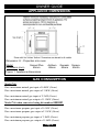
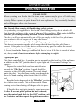
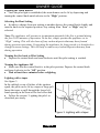
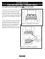
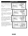
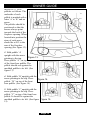
5108617/01
OWNER GUIDE
Sonnet Plus
Anthem
Genesis
Soraya
Model 746
(GC No. 32-032-57)
INSET LIVE FUEL EFFECT GAS FIRE
THIS APPLIANCE IS FOR USE WITH NATURAL GAS (G20)
WHEN CONVERTED USING CONVERSION KIT NO. 0595221 THIS
APPLIANCE IS FOR USE WITH PROPANE GAS (G31)
We trust that these instructions give sufficient details to enable this appliance to be
installed and maintained satisfactorily. However, if further information is required, our
Baxi Fires Division Technical Helpline will be pleased to help.
Telephone 08706 061 065 (National call rates apply in the United Kingdom)
This guide is intended to help you care for your Baxi Fires Division gas fire. Please read
thoroughly before using and keep for future reference
This guide to be left with the owner
©
OWNER GUIDE
Safety First.
Baxi Fires Division fires are CE Approved and designed to meet the appropriate British
Standards and Safety Marks.
Quality and Excellence.
At the heart of every Baxi Fires Division fire.
All Baxi Fires Division fires are manufactured to the highest standards of quality and
excellence and are manufactured under a BS EN ISO 9001 quality system accepted by
the British Standards Institute.
The Highest Standards
Baxi Fires Division is a member of the Society of British Gas Industries which works to
ensure high standards of safety, quality and performance.
Careful Installation
Baxi Fires Division is a CORGI registered company. All our gas fires must be
installed by a competent CORGI Registered Installer in accordance
with our Installer Guide and should not be fitted directly on to a
carpet or floor of combustible material.
Baxi Fires Division Heating, Erdington, Birmingham B24 9QP
www.firesandstoves.co.uk
Because our policy is one of constant development and improvement, details may vary slightly from those
given in this publication
Page 2
OWNER GUIDE
LIST OF CONTENTS
Section
SAFETY
APPLIANCE DIMENSIONS
GAS CONSUMPTION
OPERATING YOUR FIRE
Lighting the pilot
Lighting the Main Burner
Lighting with a taper
Selecting the Heat Setting
CLEANING
Burner
Ceramic fuel effect and Rear Wall
Metal Parts
FUEL BED REFITTING - CERAMIC COALS
FUEL BED REFITTING - CERAMIC PEBBLES
MAINTENANCE
Owner Replaceable Parts
Regular maintenance
Servicing
USEFUL TELEPHONE NUMBERS
Page
4
6
6
7
7
8
8
8
9
9
9
9
10
12
16
16
16
16
17
This gas fire is designed to meet the most stringent quality, performance and safety
requirements to provide you with many years’ trouble-free service.
This guide aims to improve your understanding and appreciation of your gas fire by
providing simple and informative instructions to ensure that you benefit from the
excellent performance and features it has to offer.
Page 3
OWNER GUIDE
SAFETY
IF YOU SMELL GAS
DON’T SMOKE
EXTINGUISH ALL NAKED FLAMES
DON’T TURN ELECTRICAL SWITCHES ON OR OFF
TURN OFF THE GAS SUPPLY AT THE METER
OPEN DOORS AND WINDOWS TO GET RID OF THE GAS
IMMEDIATELY CALL THE GAS EMERGENCY SERVICE – SEE YOUR LOCAL TELEPHONE
DIRECTORY
Do have the fire installed by a competent person. In the United Kingdom, installation
must be in accordance with the latest edition of the Gas Safety (installation & use)
Regulations. In the Republic of Ireland, installation must be in accordance with all
national and local regulations in force.
Do have the chimney swept prior to installation if it was previously used for solid fuel.
Do have the fire installed in accordance with the installation instructions
Do provide a minimum clearance of 750mm from the top surface of the hearth to any
shelf made of wood or other combustible material where the shelf is not more than
150mm deep. For a shelf deeper than 150mm, add 12.5mm to the clearance for every
25mm of additional shelf depth.(See graph1)
Graph 1. Combustible shelf clearances
Page 4
OWNER GUIDE
Do always use a fireguard complying with BS 8423 for the protection of young
children, the elderly or infirm.
Do wait three minutes before attempting to relight if the fire is switched off or the
flames are extinguished for any reason.(Your fire is fitted with a safety device that will
automatically shut off the gas supply to the fire, if for any reason , the flame goes out)
Do get advice about the suitability of any wall covering near your fire. Soft wall
coverings (e.g. embossed vinyl, etc.) which have a raised pattern are easily affected by
heat. They may, therefore, scorch or become discoloured when close to a heating
appliance. Please bear this in mind whenever you are considering redecorating.
Do provide a minimum side clearance as detailed in figure 1. Please bear this in mind if
ever you are altering the room.
Don’t hang clothing, towels or any other fabrics over the fire.
Don’t put more loose coals / pebbles on the fire than the number given in this guide or
use any coals / pebbles other than those authorised for this fire. Incorrect combustion
could result.
Don’t put paper or other materials onto your fire.
Don’t use the fire with damaged base ceramics.
Don’t place any combustible material (rugs, carpet, plastic tiles, etc.) on the hearth
Don’t attempt to clean or service the fire until it has been switched off and allowed to
cool completely.
Page 5
OWNER GUIDE
APPLIANCE DIMENSIONS
Dimension ‘A’ - Projection into room
Model
Dimension (mm)
Sonnet Plus
65mm
Anthem
68mm
Genesis
65mm
Figure 1. Appliance dimensions
GAS CONSUMPTION
Model 746
Has a maximum natural gas input of 6.0kW (Gross)
Has a maximum natural gas output of 3.0kW (Gross)
Has a minimum natural gas input of 2.3kW (Gross)
Has a minimum natural gas output of 1.15kW (Gross)
Model 746 when converted using kit number 0595221
Has a maximum propane gas input of 6.1kW (Gross)
Has a maximum propane gas output of 3.1kW (Gross)
Has a minimum propane gas input of 3.8kW (Gross)
Has a minimum propane gas output of 1.8kW (Gross)
Page 6
Soraya
65mm
OWNER GUIDE
OPERATING YOUR FIRE
PLEASE NOTE
When operating your fire for the first time, some vapours may be given off which may
cause a slight odour and could possibly set off any smoke alarms in the immediate
vicinity. These vapours are quite normal with new appliances. They are totally harmless
and will disappear after a few hours use.
The Oxysafe flame sensing & flue blockage safety system.
For your safety, this appliance is fitted with a flue blockage safety device which will
shut down the appliance in the event of abnormal flue conditions. This device is NOT a
substitute for an independently mounted Carbon Monoxide detector.
The device will also automatically shut off the gas supply to the fire if the pilot flame
goes out due to lack of oxygen or for any other reason.
If this device starts to repeatedly shut off the gas, get expert advice.
This device incorporates a probe which senses that the heat from the pilot flame is
correct. If this probe is cool, the device will prevent any gas flow unless the control
knob is kept depressed at the “Pilot/Ign” position.
If, for any reason, the flames go out when the fire is hot or if the fire is turned off when
hot, always wait at least three minutes before attempting to relight.
Lighting the pilot
This fire is controlled by a 4-position gas tap mounted on the front leg of the appliance.
In addition to the “Off” position there is a pilot light and 2 heat control settings. See
figure 2.
Depress the control knob and turn anticlockwise
towards the “Pilot/Ign” position. A spark should be
generated at the pilot while turning. The spark should
ignite the pilot. The pilot flame can be seen through the
lower left hand opening in the front of the fuel effect
bed.
Keep the button depressed at the “Pilot/Ign” position
for a further ten seconds. This will prevent the flamesensing device from shutting off the gas while its probe
warms up.
If the pilot does not ignite instantly, repeat procedure.
If after 10 seconds pilot ignition has not occurred,
turn the control knob back to the “Off” position, wait
for 3 minutes and then repeat the ignition procedure. Figure 2.
Page 7
OWNER GUIDE
Lighting the Main Burner
Once the pilot light is established, the main burner can be lit by depressing and
turning the control knob anticlockwise to the “High” position.
Selecting the Heat Setting
In order to change from one setting to another depress the control knob slightly and
turn the knob to the required position. Any setting from “Low” to “High” may be
selected.
Note: The appliance will operate to its maximum potential if the flue is primed during
the first 20-30 minutes of operation. To do this, simply operate the appliance at its
“High” setting. This will also burn off any carbon deposits that may have formed
during previous operations. If operating the appliance for long periods it is beneficial to
change between settings. This will help to remove any carbon deposits that may form
during operation.
Turning the fire back to Pilot Setting
Depress the control knob and turn clockwise until the pilot setting is reached.
Turning the Appliance Off
Make sure that the control knob is in the pilot position. Depress the control knob
and turn clockwise to the “Off” position.
Wait at least three minutes before relighting.
Lighting with a taper
See figure 3.
In the unlikely event of failure of the ignition
spark, the pilot can be lit by a taper or long spill.
Insert the taper or spill through the lower left
hand opening in the front of the fuel effect bed.
Follow the section ‘ Lighting the pilot’ as
described previously.
Figure 3. Lighting with a taper
Page 8
OWNER GUIDE
CLEANING
To maintain the high performance and quality finish of your Baxi Fires Division
appliance, please follow these guidelines:
Before attempting to clean the fire, please remember to turn off the fire and wait for
the appliance to cool. The fire will retain heat for some time before cleaning can begin.
If any pieces of debris are found in the firebox, have the chimney inspected before
further use.
Metal Parts
Clean the metal parts with a slightly damp, lint free non-abrasive cloth and then dry.
Do not use abrasive cleaners, as these will scratch the fire surface.
Front surround -Clean the metal parts with a slightly damp cloth and then dry. If
this does not work apply a very small amount of ‘baby oil’ to a lint free, non-abrasive
cloth and wipe over the surface. Use a clean cloth to wipe off the oil.
Ceramic fuel effect and Rear Wall
This product uses fuel effect pieces and burner compartment rear wall
containing Refractory Ceramic Fibres (RCF), which are man-made vitreous
silicate fibres. Excessive exposure to this material may cause irritation to eyes, skin
and respiratory tract. Consequently, it is important to take care when handling
these articles to ensure that the release of dust is kept to a minimum.
Light coatings of soot will usually be burnt off during the normal operation of the
fire.
Should any soot accumulation become excessive, the fuel effect pieces and walls
should be removed from the fire for cleaning.
Cleaning should be carried out in a well ventilated area or in the open air by gently
brushing with the pieces held away from your face so that you avoid inhaling the dust.
We suggest that you remove the coals / pebbles in the reverse order to that shown in
the fuel bed refitting instructions.
Burner
The burner surface can be carefully cleaned to remove any loose particles after
taking off the coals / pebbles. Make sure that no particles are pushed into the burner
holes.
Page 9
OWNER GUIDE
FUEL BED REFITTING - CERAMIC COALS
This section is for models supplied with ‘Coal’ effect fuel bed only.
For ‘Pebble fuel bed’ see section ‘fuel bed refitting - ceramic pebbles’
1. Place the rear base coal in the firebox.
It should rest on the ledges at the rear
sides of the burner unit. When located
gently move the rear base coal so that it is
as far forward as possible. The amount of
movement will be negligible (See figure
4).
2. Place the front base coal in the firebox
with its bottom front locating over the
front rim of the firebox. Pull the coal
Figure 4. Rear Base Coal Position
forward so that it locates immediately
behind the front rim of the firebox.
(See figure 5).The front base coal will
touch the rear base coal as it is located.
Figure 5. Front base coal position
Page 10
OWNER GUIDE
There are two types of loose coals.
These are identified with the letter
“A” or “B” on the underside of the
coal.
There are three “A” coals and two
“B” coals.
3. Place a type “A” coal between
Figure 6.
the front and rear base coals with
the letter “A” upright and so that the
coal is against the left side of the
firebox. See figure 6.
4. Place a type “B” coal between the
front and rear base coals as shown in
figure 7. The letter “B” should be
upright.
5. Place a type “A” coal between
the front and rear base coals with
the letter “A” upright. The top of
the coal should rest against the
centre coal of the rear base coal as
shown in figure 8.
Figure 7.
Figure 8.
6. Place the remaining type “B” coal
at the right side of the firebox
between the front and rear base coals.
The letter “B” should be upright. The
coal should touch the right side of the
firebox. See figure 9.
Figure 9.
Page 11
OWNER GUIDE
7. Place the remaining type “A” coal
between the front and rear base coals.
The letter “A” should be upside down
with its rear face between the right
and centre coals of the rear base coal.
Angle the coal so that the gap
between it and the type “B” coal to its
right is appreciably larger than the
gap between it and the type “A” coal Figure 10.
to its left but do not have it touching the type “A” coal. This will give the best flame
effect. See figure 10.
FUEL BED REFITTING - CERAMIC PEBBLES
This section is for models supplied with ‘Pebbles’ effect fuel bed only.
For ‘Coal fuel bed’ see section ‘Fuel bed refitting - ceramic coals’
1. Place the rear base pebble in the firebox. It
should rest on the ledges at the rear sides of the
burner unit. When located gently move the rear
base pebble so that it is as far forward as possible.
The amount of movement will be negligible (See
figure 11).
2. Place the front base pebble in the firebox with its
bottom front locating over the front rim of the
firebox. Pull the pebble forward so that it locates
Figure 11 Rear Base Pebble
immediately behind the front rim of the firebox.
Position
(See figure 12).The front base coal will touch
the rear base coal as it is located.
Figure 12 Front Base Pebble
Position
Page 12
OWNER GUIDE
Install the 11 loose
pebbles as follows. The
underside of each
pebble is marked with a
letter ‘A’ to ‘K’ and an
arrow.
The pebbles should be
positioned so that the
arrows always point
towards the back of the
fireplace opening. When
located into position the
stem of each arrow
should be at 90° to the
rear of the fireplace
opening (See figure 13).
3. Hold pebble ‘A’
upright with the arrow
Figure 13.
pointing to the top.
Place pebble “A” on top
of the front base pebble. The
pebble should rest against the
moulded pebble to its left. (See
figure 13).
4. Hold pebble ‘B’ upright with the
arrow pointing to the top. Place
Figure 14.
pebble “B” on top of the front
base pebble. (See figure 14).
5. Hold pebble ‘C’ upright with the
arrow pointing to the top. Place
pebble “C” on top of the front base
pebble. It should lie against the
moulded pebble to its left. (See figure Figure 15.
15).
Page 13
OWNER GUIDE
6. Hold pebble ‘D’ upright with the
arrow pointing to the top. Place
pebble “D” on top of the base front
pebble. It should rest against the
moulded pebble to its right. (See
figure 16).
7. Hold pebble ‘E’ upright with the
arrow pointing to the top. Place
pebble ‘E’ between the front and
rear base pebbles. It should rest
against the side of the firebox. (See
figure 17).
Figure 16.
8. Hold pebble ‘F’ upright with the
arrow pointing to the top. Place
Figure 17.
pebble ‘F’ between the front and
rear base pebbles. It should rest on
top of pebble ‘A’&’B’. (See figure
18).
9. Hold pebble ‘G’ upright with the
arrow pointing to the top. Place
pebble ‘G’ between the front and rear
Figure 18.
base pebbles. It should rest on top
of pebble ‘B’ & ‘C’ and rest against
the moulded pebble in the rear
pebble base. (See figure 19).
Figure 19.
Page 14
OWNER GUIDE
10. Hold pebble ‘H’ upright with the
arrow pointing to the top. Place
pebble ‘H’ between the front and rear
base pebbles. It should rest in
between pebbles ‘C’ & ‘D’ and
against the moulded pebble in the rear
pebble base. (See figure 20).
11. Hold pebble ‘I’ upright with the
arrow pointing to the top. Place
pebble ‘I’ between the front and
rear base pebbles. It should rest
against the side of the firebox (See
figure 21).
Figure 20.
12. Hold pebble ‘J’ upright with the
Figure 21.
arrow pointing to the top. Place
pebble ‘J’ on top of the base pebble
rear. (See figure 22)
13. Hold pebble ‘K’ upright with the
arrow pointing to the top. Place
pebble ‘K’ on top of the base pebble
rear. (See figure 23)
Figure 22.
Figure 23.
Page 15
OWNER GUIDE
MAINTENANCE
Regular maintenance
In order to achieve and maintain high levels of personal safety and performance
efficiency, it is essential that the opening at the back of the fire and the flue are kept
clear of any form of obstruction. It is possible that deposits of mortar or soot could fall
and accumulate causing the flue to be blocked or restricted and so preventing proper
clearance of dangerous exhaust fumes.
In the United Kingdom it is the law that a landlord must have any gas appliance, flue
and pipework which is situated in a tenant’s premises checked for safety at least every
twelve months by a competent person (In the U.K, a CORGI registered installer).
We recommend that all gas appliances and their flues, wherever situated, are checked
annually.
Servicing
In the United Kingdom servicing can be carried out either by a Baxi Fires Division
service engineer or a CORGI registered installer.
If you require your fire to be serviced, please contact Baxi Fires Division Service
on 08706 090 081 and quote the following details;
Model name and number.
Appliance serial no. (To be found on the plate close to the control knob.)
If you wish to replace any of the owner replaceable parts listed below, spare parts
are available nationwide via the ‘interpart stockist network’. For your local
stockist consult Yellow pages under Central Heating.
When ordering please quote the part number shown below.
Owner Replaceable Parts
Description
Ceramic rear wall
Part No
0579399
Coal model
Front coal
Rear base coal
Pack of loose coals
5108541
5108542
0582839
Pebble model
Front pebble
Rear base Pebble
Pack of loose Pebbles
5108543
5108544
3002773
Page 16
OWNER GUIDE
When fitting replacement parts, follow the instructions contained in this guide.
It is important that only Baxi Fires Division approved parts are used for
maximum safety.
In the United Kingdom, for general advice about gas and your gas fire call our
Technical Helpline
08706 061 065.
In the Republic of Ireland call 0044 08706 061 065 for all enquiries.
USEFUL TELEPHONE NUMBERS
General advice about gas and your gas fire:
BAXI FIRES DIVISION TECHNICAL HELPLINE
08706 061 065.
To report faults or arrange for your fire to be serviced:
BAXI FIRES DIVISION SERVICE
08706 090 081.
For sales or product information:
BAXI FIRES DIVISION SALES
08706 061 067.
To order spares
Spare parts are available nationwide via the ‘interpart stockist network’. For your
local stockist consult Yellow pages under ‘Central Heating’.
CALLERS IN THE REPUBLIC OF IRELAND
Call 0044 08706 061 064
Page 17