1
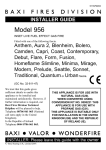
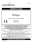
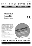
5113426/01
OWNER GUIDE
Model
739
OPEN DECORATIVE
GAS FIRE
(GC No. 32-032-54)
THIS APPLIANCE IS FOR USE WITH NATURAL GAS (G20).
WHEN CONVERTED USING CONVERSION KIT NO. 0595211 THIS
APPLIANCE IS FOR USE WITH PROPANE GAS (G31).
THIS APPLIANCE IS SUITABLE ONLY FOR INSTALLATION IN THE UNITED
KINGDOM (GB) AND THE REPUBLIC OF IRELAND (IE).
We trust that this guide gives sufficient details to enable this appliance to be installed
and maintained satisfactorily. However, if further information is required, our
Baxi Fires Division Technical Helpline will be pleased to help.
Please telephone 08706 061 065 (National call rates apply).
In the Republic of Ireland telephone 0044 8706 061 065
This guide is intended to help you care for your Baxi fires division gas fire. Please read
thoroughly before using and keep for future reference.
INSTALLER: Please leave this guide with the owner
© Baxi Heating U.K. Ltd.
OWNER GUIDE
Safety First.
Baxi Fires Division fires are CE Approved and designed to meet the appropriate British
Standards and Safety Marks.
Quality and Excellence.
At the heart of every Baxi Fires Division fire.
All Baxi Fires Division fires are manufactured to the highest standards of quality and
excellence and are manufactured under a BS EN ISO 9001 quality system accepted by
the British Standards Institute.
The Highest Standards
Baxi Fires Division is a member of the Society of British Gas Industries which works to
ensure high standards of safety, quality and performance.
Careful Installation
Baxi Fires Division is a CORGI registered company. All our gas fires must be
installed by a competent CORGI Registered Installer in accordance
with our Installer Guide and should not be fitted directly on to a
carpet or floor of combustible material.
Baxi Fires Division, Erdington, Birmingham B24 9QP
www.firesandstoves.com
Because our policy is one of constant development and improvement, details may vary slightly from those
given in this publication
Page 2
OWNER GUIDE
LIST OF CONTENTS
Section
Page
SAFETY
GAS CONSUMPTION
APPLIANCE DIMENSIONS
OPERATING THE FIRE
The Oxysafe flame sensing & flue blockage safety system.
To light the fire.
Lighting with a taper.
CLEANING
Metal parts.
Ceramic fuel effect .
Burner.
CERAMIC FUEL EFFECT REFITTING
FITTING THE LOWER FIREFRONT
MAINTENANCE
Regular maintenance.
Servicing.
USEFUL TELEPHONE NUMBERS
4
5
6
6
6
7
8
8
8
8
9
9
9
10
10
10
11
This gas fire is designed to meet the most stringent quality, performance and safety
requirements to provide you with many years’ trouble-free service.
This guide aims to improve your understanding and appreciation of your gas fire by
providing simple and informative instructions to ensure that you benefit from the
excellent performance and features it has to offer.
Page 3
OWNER GUIDE
SAFETY
IF YOU SMELL GAS
DON’T SMOKE
EXTINGUISH ALL NAKED FLAMES
DON’T TURN ELECTRICAL SWITCHES ON OR OFF
TURN OFF THE GAS SUPPLY AT THE METER
OPEN DOORS AND WINDOWS TO GET RID OF THE GAS
IMMEDIATELY CALL THE GAS EMERGENCY SERVICE - SEE YOUR
LOCAL TELEPHONE DIRECTORY
Do have the fire installed by a competent person. In the United Kingdom,
installation must be in accordance with the latest edition of the Gas Safety
(installation & use) Regulations. In the Republic of Ireland, installation must be in
accordance with all national and local regulations in force.
Do have the chimney swept prior to installation if it was previously used for solid fuel.
Do have the fire installed in accordance with the installation instructions.
Do provide a minimum clearance of 860mm from the base of the hotbox to any
shelf made of wood or other combustible material where the shelf is not more than
150mm deep. For a shelf deeper than 150mm, add 12.5mm to the clearance for every
25mm of additional shelf depth (See graph1).
Graph 1. Combustible shelf clearances
Do provide a suitable guard that complies with BS 8423 for the protection of young
children, the elderly and the infirm. Such a guard is also recommended for the
protection of pet animals. (Although this fire conforms to all the applicable
Page 4
OWNER GUIDE
standards, it is a heating appliance and certain parts of its surface will become hot.).
Do wait three minutes before attempting to relight if the fire is switched off or the
flames are extinguished for any reason. (Your fire is fitted with a safety device that will
automatically shut off the gas supply to the fire if, for any reason, the flames
go out.).
Do get advice about the suitability of any wall covering near your fire. Soft wall
coverings (e.g. embossed vinyl, etc.) which have a raised pattern are easily affected
by heat. They may, therefore, scorch or become discoloured when close to a heating
appliance. Please bear this in mind whenever you are considering redecorating.
Do provide a minimum side clearance as detailed in figure 1. Please bear this in mind if
ever you are considering altering the room.
Don’t hang clothing, towels or any other fabrics over the front of the fire.
Don’t add any extra ceramic fuel effect pieces above the number stated in the installer
and owner guide supplied with the ceramic fuel effect. This should have been placed
inside or attached to this guide by the installer. This could cause incomplete combustion
and consequent safety hazard.
Don’t put paper or any other material on the fire.
Don’t place any combustible material (rugs, carpet, plastic tiles, etc.) on the hearth.
Don’t attempt to clean or service the fire until it has been switched off and allowed to
cool completely.
GAS CONSUMPTION
Model 739
Has a maximum natural gas input of 6.85kW (Gross)
Has a minimum natural gas input of 2.3kW
Model 739 when converted using kit number 0595211
Has a maximum propane gas input of 6.7kW (Gross)
Has a minimum propane gas input of 4.0kW
Page 5
OWNER GUIDE
APPLIANCE DIMENSIONS
Firefront
Azure
Quattro / Anthem
Majestic
Dimension 'X' (mm)
400
390
400
Dimension 'Y' (mm)
65
65
50
Figure 1. Appliance dimensions
OPERATING THE FIRE
PLEASE NOTE
When operating your fire for the first time, some vapours may be given off which may
cause a slight odour and could possibly set off any smoke alarms in the immediate
vicinity. These vapours are quite normal with new appliances. They are totally harmless
and will disappear after a few hours use.
The Oxysafe flame sensing & flue blockage safety system.
For your safety, this appliance is fitted with a flue blockage safety device that will shut
down the appliance in the event of abnormal flue conditions. This device is NOT a
substitute for an independently mounted Carbon Monoxide detector.
The device will also automatically shut off the gas supply to the fire if the pilot flame
Page 6
OWNER GUIDE
goes out due to lack of oxygen or for any other reason.
If this device starts to repeatedly shut off the gas, get expert advice.
This device incorporates a probe that senses that the heat from the pilot flame is correct.
If this probe is cool, the device will prevent any gas flow unless the control knob is held
in at the ignition position.
If, for any reason, the flames go out when the fire is hot or if the fire is turned off when
hot, always wait at least three minutes before attempting to relight.
To light the fire.
Depress the control knob and rotate it
anticlockwise to the pilot ignition position. A
‘click’ will be heard as the integral piezo
operates. A flame should appear at the pilot.
Keep the control knob depressed and hold the
pilot ignition position for five seconds. When
the control knob is released the pilot flame
should remain lit. If a flame does not appear at
the pilot then turn the control knob clockwise
to the ‘OFF’ position and repeat the above.
Figure 2. Lighting the fire
When the pilot burner is operating properly,
gradually turn the control knob anti-clockwise
to ‘HIGH’ position. (Depress the knob slightly to get past the pilot ignition position).
The main burner should now light.
Depress the control knob slightly to release from the ‘HIGH’ position and turn back
(clockwise) to ‘LOW’. While turning, the burner flames should gradually become lower
but remain alight. Depress the control knob slightly to release from the ‘LOW’ position
and turn back (clockwise) to the Pilot ignition position. The main burner should
extinguish but the pilot should remain alight. Depress the control knob slightly and turn
back (clockwise) to turn OFF. This will extinguish the pilot.
While cooling, the ceramic fuel effect may make some crackling noises. This is quite
normal.
!
If the flames go out while setting the control, repeat the full lighting procedure.
!
If the flames repeatedly go out have the fire serviced.
!
Please note. When first turned on the flames will appear predominantly blue. The
ceramic fuel effect will take time to warm up. Although some glow will be seen after
approximately ten minutes, the full visual effect will only be apparent after a somewhat
longer time.
!
The appliance will operate to its maximum potential if the flue is primed during the
first 20 – 30 minutes of operation. To do this, simply turn the control knob to its
Page 7
OWNER GUIDE
‘HIGH’ setting. This will also burn off any carbon deposits that may have formed
during previous operations.
!
If operating the appliance for long periods it is beneficial occasionally to change
the settings. This will also help to remove any carbon deposits that may form during
operation.
Lighting with a taper.
See figure 3.
In the unlikely event of failure of the ignition
spark, the pilot can be lit by a taper or long
spill. Insert the taper or spill between the second
and third left hand ceramic fuel effect pieces on
the first row. Operate the control knob as
described in the section headed ‘To light the
fire’.
Figure 3. Lighting with a taper
CLEANING
Turn the fire off and allow it to cool completely before attempting any cleaning. Note
that the fire will retain heat for some time after it has been turned off.
If large pieces of debris are found anywhere in the fireplace, have the chimney
inspected before further use.
Metal parts.
Clean the metal parts with a slightly damp cloth and then dry. Do not use abrasive
cleaners, they could scratch the surface.
Ceramic fuel effect .
This product uses fuel effect pieces containing Refractory Ceramic Fibres
(RCF), which are man-made vitreous silicate fibres. Excessive exposure to this
material may cause irritation to eyes, skin and respiratory tract.
Consequently, it is important to take care when handling these articles to
ensure that the release of dust is kept to a minimum.
! Light coatings of soot will usually be burnt off during the normal operation of the
fire.
! Should any soot accumulation become excessive, the ceramic fuel effect pieces
should be removed from the fire for cleaning.
Page 8
OWNER GUIDE
! Cleaning should be carried out in a well-ventilated area or in the open air by gently
brushing with the pieces held away from your face so that you avoid inhaling the dust.
! We do not recommend the use of a normal domestic vacuum cleaner that may blow
dust back into the air.
! We suggest that you remove the ceramic fuel effect pieces in the reverse order to
that shown in the installer and owner guide supplied with the ceramic fuel effect. This
should have been placed inside or attached to this guide by the installer.
Burner.
Remove any deposits of soot or other foreign matter from the the burner with a dry soft
brush. Be careful not to brush any particles into the open slots. Remove any particles
from the slots with a vacuum cleaner fitted with a soft brush attachment. Do not poke
wire, etc. into the slots in the burner.
CERAMIC FUEL EFFECT REFITTING
The installer and owner guide for the ceramic fuel effect is separate from this guide. The
installer may have attached it to this guide or placed it inside. It is important that the
installer and owner guide for the ceramic fuel effect is followed correctly. If replacing
the ceramic fuel effect, where a new guide is supplied, follow the installer and owner
guide supplied with the replacement fuel effect.
Keep the replacement installer and owner guide with this owner guide for future
reference.
FITTING THE LOWER FIREFRONT
Decorative firefront.
Place the decorative firefront on the hearth and
centralise to the appliance.
‘Quattro’ and ‘Anthem’ firefront only
Note:Before removing the ‘Quattro’ / ‘Anthem’
firefront it is necessary to remove the ceramic fuel
effect.
! Remove the fuel effect carefully and place aside.
We recommend that the fuel effect is removed in the
reverse order to that shown in the fitting sections.
! Remove the lower ‘ashpan’.
Figure 4. Hanging the
! Lift the firefront clear of the burner.
firefront
! To fit the firefront, locate the firefront as in
Page 9
OWNER GUIDE
figure 4. The hooks should fit into the slots on the
burner tray.
! The lower ‘ashpan’ should be located as in figure
5.
Figure 5. Lower ‘ashpan’
location
MAINTENANCE
Regular maintenance.
In order to achieve and maintain high levels of personal safety and performance
efficiency, it is essential that the opening at the back of the fire and the flue are kept
clear of any form of obstruction. It is possible that deposits of mortar or soot could fall
and accumulate causing the flue to be blocked or restricted and so preventing proper
clearance of dangerous exhaust fumes.
In the United Kingdom it is the law that a landlord must have any gas appliance, flue
and pipework which is situated in a tenant’s premises checked for safety at least every
twelve months by a competent person (In the U.K, a CORGI registered installer).
We recommend that all gas appliances and their flues, wherever situated, are checked
annually.
Page 10
OWNER GUIDE
Servicing.
! In the United Kingdom servicing can be carried out either by a Baxi Fires Division
service engineer or a CORGI registered installer.
! If you require your fire to be serviced, please contact Baxi Fires Division Service
on 08706 090 081 and quote the following details;
IMPORTANT
To help us quickly help you, please try to have the following information available
before you contact us:
Type of fire.
Model/Name.
Serial Number.
You will also be asked for the fault, problem or request plus your Post Code.
! If you wish to replace any of the ceramic fuel effect pieces, spare parts
are available nationwide via the ‘interpart stockist network’. For your local
stockist consult Yellow pages under Central Heating.
! When fitting replacement parts it is important that only approved parts are
used for maximum safety.
USEFUL TELEPHONE NUMBERS
General advice about gas and your gas fire:
BAXI FIRES DIVISION TECHNICAL HELPLINE
08706 061 065.
To report faults or arrange for your fire to be serviced:
BAXI FIRES DIVISION SERVICE
08706 090 081.
For sales or product information:
BAXI FIRES DIVISION SALES
08706 061 067.
To order spares
Spare parts are available nationwide via the ‘interpart stockist network’. For your
local stockist consult Yellow pages under ‘Central Heating’.
CALLERS IN THE REPUBLIC OF IRELAND
Call 0044 8706 061 065
Page 11