1
GENERAL
REV NO.
TITLE
m
19A705178
ELECTRIC
CONT ON SHEET
22
SH NO.
21
ROCKWELL MODEM TEST
SPECIFICATION/PURCHASE PART DRAWING
CONT ON SHEET
SH NO.
FIRST MADE FOR
F. C. F. O.
REVISIONS
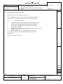
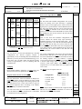
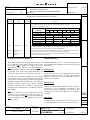
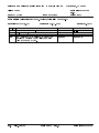
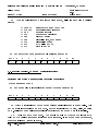
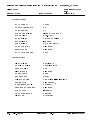
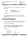
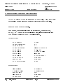
R96FT Interface Memory Definitions (Continued)
Mnemonic
Name
Memory
Location
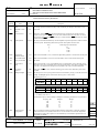
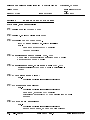
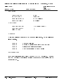
SDIS
Scrambler Disable
0:7:5
When control bit SDIS is a one, the transmitter scrambler circuit is removed from the data path.
SEPT
Short Echo
Protector Tone
0:7:0
When control bit SEPT is a one, the echo protector disable tone is 30 ms long rather than 185 ms
(See TSB)
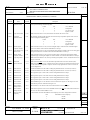
TBA
Transmitter Buffer
Available
0:E:0
This status bit resets to zero when the host processor writes data to transmitter data register 0:0. When
the transmitter empties register 0:0, this bit sets to a one.
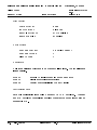
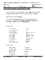
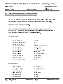
TCF
Transmitter Carrier
Frequency
0:9:3
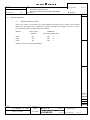
Control bit TCF selects the modulator carrier frequency for V.29FT configurations as follows:
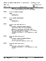
Description
TCF
Modular Carrier Frequency
0
1
1700 Hz
1800 Hz
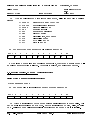
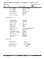
TIA
Transmitter
Interrupt Active
0:E:7
This status bit is a one whenever the transmitter is driving IRQ to a zero.
TIE
Transmitter
Interrupt Enable
0:E:2
When the host processor writes a one in control bit TIE, the IRQ line of the hardware interface is
driven to zero when status bit TBA is at a one.
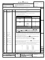
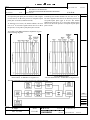
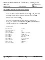
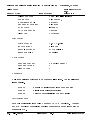
TLVL
Transmitter Level
Field
0:4:2-4
The transmitter analog output level is determined by eight TLVL codes, as follows:
TLVL
Transmitter Analog Output
0
-1 dBm ± 1 dB
1
-3 dBm ± 1 dB
2
-5 dBm ± 1 dB
3
-7 dBm ± 1 dB
4
-9 dBm ± 1 dB
5
-11 dBm ± 1 dB
6
-13 dBm ± 1 dB
7
-15 dBm ± 1 dB
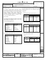
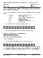
TOD
Train-On-Data
1:6:7
When control bit TOD is a one, it enables the train-on-data algorithm to converge the equalizer if the
signal quality degrades sufficiently. When TOD is a one, the modem still recognizes a training
sequence and enters the force train state. A BER of approximately 10-3 for 0.5 seconds initiates trainon-data.
TPDM
Transmitter Parallel
Data Mode
0:7:2
When control bit TPDM is a one, the transmitter accepts data for transmission form the transmitter
data register (0:0) rather than the serial hardware data input.
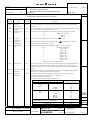
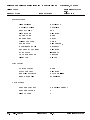
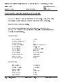
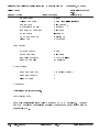
(None)
Transmitter
Configuration
*Each step above is a 2 dB change ±0.2 dB.
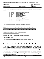
0:6:0-7
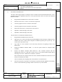
The host processor configures the transmitter by writing a control byte into the transmitter
configuration register in its interface memory space. (See TSB)
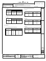
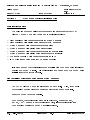
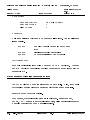
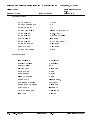
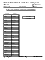
Transmitter Configuration Control Codes
Control codes for the modem transmitter configurations are:
Configuration
V.29
V.27 bis/ter
Configuration Code (Hex)
FT/4800
FT/2400
1C
1A
19
0A
09
4800 long
2400 long
4800 short
2400 short
14
12
11
22
21
02
01
FT/9600
FT/7200
FT/4800
9600
7200
4800
611
411
2400/4800 bps Gearshift/V.29 descrambler
2400/4800 bps Gearshift/V.27 bis/ter descrambler
MADE BY
ISSUED
K P Dotson 11-19-86
Nov. 19, 1986
V.21 Channel 2
See FSKT
Tone transmit
80
APPROVALS
DCB
11-18-86
L30
M. R. P. D.
LYNCHBURG
DIV OR DEPT.
LOCATION
PRINTS TO
19A705178
CONT ON SHEET
22
SH NO.
21