1
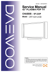
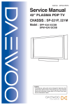
Service Manual
S/M NO. : TSP900PEF0
32" PLASMA PDP TV
CHASSIS : SP-900PF
Model : DPP-32F1BMB
Caution
: In this Manual, some parts can be changed for improving. their
performance without notice in the parts list. So, if you need the
latest parts information, please refer to PPL(Parts Price List)in
Service Information Center.
Contents
I. Parts with the exception of MODULE
1. Safety Precautions .................................................................................................................3
2. Product Specification .............................................................................................................4
2-1. SPECIFICATION ............................................................................................................4
2-2. Available Input Signal .....................................................................................................6
3. The Feature of Inside .............................................................................................................7
3-1. Main PCB’s Connection Diagram ...................................................................................7
3-2. Main PCB’s Block Diagram.............................................................................................7
3-3. Power Specification ........................................................................................................8
4. Default Setting in User Menu OSD ........................................................................................9
5. Service Mode .......................................................................................................................11
6. Adjusting Method .................................................................................................................14
6-1. MODULE POWER Adjustments and Test Point Locations...........................................14
6-2. White Balance Adjustments..........................................................................................14
7. Noticeable Points While Assembling....................................................................................16
8. Software Upgrade Methord ..................................................................................................18
8-1. Pic upgrade ..................................................................................................................18
8-2. Flash Upgrade ..............................................................................................................23
9. Trouble Shooting ..................................................................................................................29
10. Assembly List .....................................................................................................................40
11. Structure of PDP SET ........................................................................................................42
12. Exploded View ...................................................................................................................43
II. Parts of MODULE
1. PDP MODULE SERVICE MANUAL
-2-
I. Parts with the exception of MODULE
1. Safety Precautions
(1) When moving or laying down a PDP Set, at least two people must work together.
Avoid any impact towards the PDP Set.
(2) Do not leave a broken PDP Set on for a long time. To prevent any further damages, after
checking the condition of the broken Set, make sure to turn the power(AC) off.
(3) When opening the BACK COVER, you must turn off power(AC) to prevent any electric
shock. When PDP is operating, high voltage and high current inside the Set can cause
electric shocks.
(4) When loosening screws, check the position and type of the screw.
Sort out the screws and store them separately for reassembling.
Because screws holding PCBs are working as electric circuit GROUNDING,
make sure to check if any screw is missing when assembling / reassembling.
Do not leave any screws inside the set.
(5) If you open the BACK COVER,
you will see a Panel Gas Exhaust Tube
(Picture. 1-1) inside the bracket.
If this part is damaged, the entire PDP
PANEL must be replaced. Therefore,
when working with the set, be careful not
to damage this part.
(6) A PDP Set contains different kinds of
connector cables.
When connecting or disconnecting cables,
check the direction and position of the cable
beforehand.
Picture.1-1 Panel Gas Exhaust Tube
(7) Connect / disconnect the connectors slowly with care especially FFC(film) cables
and FPC cables.
Do not connect or disconnect connectors instantaneously with force, and handle them
carefully for reassembling.
(8) Connectors are designed so that if the number of pins or the direction does not match,
connectors will not fit.
When having problem in plugging the connectors, check their kind, position, and direction.
-3-
2. Product Specification
2-1. SPECIFICATION
ITEM
SPECIFICATION
REMARK
1. GENERAL
1-1. MODEL NO
DPP-32F1BMB
1-2. CHASSIS NO
SP-900PF
1-3. SCREEN SIZE
42”(16:9)
1-4. COUNTRY
Europe, CIS, Middle east Asia
1-5. RESOLUTION
852(H) X 480(V)
1-6. REMOCON TYPE
R-55E05
1-7. SAFETY STANDARD
SASO(Saudi Arabia), PAI(Kuwait), CIS(GOST)
1-8 .TUNING METHOD
VS
1-9. MEMORY CHANNEL
99CH
2. MECHANICAL
2-1. APPEARANCE
1) WITHOUT STAND
2) WITH STAND
WxHxD = 825 x 561 x 87.8 mm
WxHxD = 825 x 603.2 x 233.6 mm
2-2. WEIGHT
1) WITHOUT STAND
2) WITH STAND
18.5 Kg
19.2Kg
3. ELECTRICAL
3-1. VIDEO INPUT
COMPOSITE(NTSC, PAL, SECAM, PAL-M/N, NTSC4.43) 1 Ports &
S-VHS(50/60Hz Y/C) 1 Ports
3-2. DTV/DVD INPUT
1080i, 720P, 480P, 480i, 576P, 576i
(Y, Pb/Cb, Pr/Cr COMPONENT SIGNAL) 1 Port
3-3.SCART INPUT
SCART(COMPOSITE, R, G, B, SOUND R/L) 1 Port
SCART(COMPOSITE, SOUND R/L) 1 Port
3-4. PC INPUT
VGA ~ WXGA(Dot clock : 110MHz), 15 PIN D-SUB 1 Port
3-5. HDMI INPUT
HDMI-H INPUT(HDMI Jack) 1 Port
3-6. TV INPUT
1) COLOR STANDARD
2) ANTENNA IN
3) RECEPTION CHANNEL
4) IF & SUBCARRIER
3-6. SOUND INPUT
PAL B/G+I/I+D/K, L-SECAM, L’--SECAM
ONE INPUT 75 Unbalanced (DIN Standard)
VHF LOW : E2 ~ S6Ch.
VHF HIGH : S7 ~ S36Ch.
UHF : S37 ~ E69 Ch.
L’-SECAM : FB, FC1, FC
PIF : 38.90MHz(PAL, L-SECAM), 33.9MHz(L’-SECAM)
SIF : 33.40MHz(B/G), 32.90MHz(I/I)
32.4MHz(D/K,L-SECAM), 40.4MHz(L’-SECAM)
VIDEO 1 Port, DTV/DVD 1 Ports, SCART 2Ports, PC / HDMI 1 Port
-4-
Basic : CB multi
Product Specification
ITEM
SPECIFICATION
3-7. SPEAKER OUTPUT
10W(R) + 10W(L)
3-8. POWER REQUIREMENT
AC 100V~240V, 50/60Hz
3-9. POWER CONSUMPTION
200 W
3-10.Phone Jack(Upgrade)
S/W Upgrade
3-11. AV OUTPUT
SCART(CVBS, SOUND R/L) 1 Port
3-12. FUNCTION
1) SCALING
2) OSD Language
3) PIP/POP
4) OTHERS
REMARK
HDMI : Screen Mode(16:9, 4:3)
PC : Screen Mode(16:9, 4:3), H/V Position, Auto
TV / AV : Screen Mode(16:9, 4:3, LB(16:9), LBS(16:9), 14:9,
LB(14:9), LBS(14:9), Auto)
COMPONENT : Screen Mode(16:9, 4:3)
19 Languages (English, Greek, Dutch, German, Russian,
Rumanian, Swedish, Danish, Finnish, Norwegian, Spanish,
Italian, Franch, Polish, Portuguese, Czech, Hungarian, Arab, Parsi)
TV, Video, S-Video / HDMI
Still, Sleep Mode, Sound Mode, Timer, Screen Mode,
TeleText, MGDi WSS
4. OPTICAL
4-1. SCREEN SIZE
32"(81.2Cm) DIAGONAL
4-2. ASPECT RATIO
16 : 9
4-3. NUMBER OF PIXELS
852(H) X 480(V)
4-4. DISPLAY COLOR
1,073,000,000 Colors (10 Bits for each RGB)
4-5. CELL PITCH
277
4-6. PEAK LUMINANCE
Typical 550cd/ß≥ (25% White Window, 60Hz)
Average 60:1 (In a bright room with 100Lux at center, 60Hz)
4-7. CONTRAST RATIO
10,000:1
4-8. VIEWING ANGLE
FREE
(H) X 830
(V) (1 Pixel = a Set of RGB Cells)
5. USERCONTROL & ACCESSORIES
5-1. CONTROL BUTTON(SET)
SOFT S/W : MOVE/CH(UP, DOWN), VOLUME(LEFT, RIGHT),
MENU, INPUT SELECT ,POWER
5-2. REMOTE CONTROL
(R-55E05)
Power, Recall, 10KEY(0~9), Still, Screen Size, Menu, TV, AV,
Multimedia, PREV PR, Mute, PR(UP/DOWN), VOL(UP/DOWN),
TeleText, CYAN, Index, Red, Green, Yellow, Reveal, Update,
Expand, Subpage, Hold, Picture Mode, Sound Mode, MTS,
Sound Effect, PIP, PR Up(Sub), Sleep Timer, EDIT, Position,
PR Down(Sub), Swap, Source(Sub), MGDI, COLOR TEMP
5-3. ACCESSORIES
REMOTE CONTROL, INSTRUCTION MANUAL, POWER CORD
5-4. OPTIONAL PARTS
WALL HANGER
-5-
Product Specification
2-2. Available Input Singnal
1) PC&HDMI
Resolution
H.Freq.(kHz)
V.Freq.(Hz)
Remar
HDMI
PC
31.469
59.940
DOS
O
O
37.861
72.809
VESA
O
O
37.500
75.000
VESA
O
O
31.469
70.087
IBM
O
O
35.156
56.250
VESA
O
O
37.879
60.317
VESA
O
O
1024 x 768
48.363
60.004
VESA
O
O
1280 x1024
63.981
60.020
VESA
O
O
640 x 480
720 x 400
800 x 600
2) Component
• 720p - 50 / 60Hz
• 480p/i - 50 / 60Hz
• 576p/i - 50 / 60Hz
3) Video
• PAL, PAL - M, PAL - N
• NTSC, NTSC 4.43
• SECAM
-6-
3. The Feature of Inside
3-1. Main PCB’s Connection Diagram
Fig.1 Main PCBs Block Diagram
3-2. Main PCB’s Block Diagram
Fig.2 Signal Block Diagram : DPP-42A2
-7-
The Feature of Inside
3-3. Power Specification
1) Input and Environmental Requirement
Input Requirement
Description
Nominal Input Voltage
Input Voltage Variation Range
Nominal Frequency
Frequency Variation Range
Inrush Current
AC100V to AC240V
AC90V to AC264V
50 /60 Hz
47Hz to 63Hz
50A peak MAX.
Environment Requirement
Description
Operating Temperature Range
Operating Humidity Range
Storage Temperature Range
Cooling system
0 to 55 Deg.
10 to 90%
-20 to 70 Deg.
Convection
2) Output Characteristics
Output
Name
STBY5V
5Vsc
9Vsc
16Vsc
Output Variable
Voltage
Typical Voltage Tolerance
(V)
Range(V)
(%)
5.0
5.0
9
16
-
1
Output Current(A)
Min.
Typical
Max.
Ripple & Noise
(mVp-p)
0
0.1
c0
c0.03
1.2
0.7
0.3
1.3
1.7
1.7
0.5
2.2
100mVp-p
200mVp-p
200mVp-p
500mVp-p
3. Connector
NO.
YW396-09V
SMW250-15
1
2
3
4
5
6
7
8
9
10
11
12
13
14
15
5V
GND
Va
GND
GND
GND
NC
Vs
Vs
AC-DET
RL_ON
VS_ON
5V_MNT
M5V_ON
GND
GND
16Vsc
16Vsc
GND
9Vsc
GND
5Vsc
STBY5V
GND
P814
P812
-8-
4. Default Setting in User Menu OSD
4-1. Picture
1) Mode
Normal
Dynamic
Cinema
User
Brightness
48
46
55
Undefined
Contrast
70
74
60
Undefined
Sharpness
7
8
6
Undefined
Colour
55
60
50
Undefined
Tint
50
50
50
Undefined
* HDMI & PC Input - Only brihgtness and contrast are available.
2) Default Value of Other Functions
Function
Default Value
Colour Temp
Normal
N.R.
On
* N.R. means the noise reduction
* HDMI & PC don't support N.R. functions
4-2. Sound
1) Mode
Normal
Movie
Music
News
User
120 Hz
32
50
48
15
Undefined
200 Hz
32
50
48
15
Undefined
500 Hz
32
38
38
32
Undefined
1.2 kHz
32
28
15
50
Undefined
3 kHz
32
28
15
50
Undefined
7.5 kHz
32
40
42
32
Undefined
12 kHz
32
48
56
15
Undefined
2) Default Value of Other Functions
Function
Default Value
Balance
0
Effect
Off
AVC
Off
-9-
Default Setting in User Menu OSD
4-3. Screen
1) Mode
16 : 9
4:3
LB (16:9)
LBS (16:9)
14 : 9
LB (14:9)
LBS (14:9)
Component
O
O
X
X
X
X
X
TV
O
O
O
O
O
O
O
AV
O
O
O
O
O
O
O
PC
O
O
X
X
X
X
X
HDMI
O
O
X
X
X
X
X
* H. Position, V. Position, and Auto screen size is available in only PC mode.
4-4. Feature
1) Mode
Function
Background
Language
Child Lock
MGDi plus
Auto Power
Default Value
10
English
Off
On
Off
* HDMI & PC don’t support MGDI function.
2) Time Setting
Function
Clock
Default Value
Undefined
Auto Clock Off Timer
On
Off
Off Time
Wake Timer
Wake Time
PM 12:00
Off
PM 12:00
3) ISM
Function
Pixel Shift
Low Bright
Image Invert
Default Value
Off
On
Off
-10-
Wake CH. Wake Vol.
1
20
5. Service Mode
To enter SERVICE MODE,
A. Press “ VOL” -> “MUTE ” -> “RECALL” -> “MUTE” button of remote controller
(R-55E05)
or
B. Press “S9” button of SERVICE REMOTE CONTROLLER.
[Note] In the first line, there is the model name and the version of the upgraded program
on the PDP set.
5-1. Default Value of Pw338B_1 and Pw338B_2
Sub Bias
Sub Gain
Bias R
Bias G
Bias B
Gain R
Gain G
Gain B
Pw338B_1
32
72
32
30
41
28
32
45
Pw338B_2
32
64
1) Pw338B_1
Sub Bias : For BRIGHTNESS adjustment (All inputs)
Sub Gain : For CONTRAST adjustment (All inputs)
Bias R : For R BRIGHTNESS adjustment (All inputs)
Bias G : For G BRIGHTNESS adjustment (All inputs)
Bias B : For B BRIGHTNESS adjustment (All inputs)
Gain R : For R CONTRAST adjustment (All inputs)
Gain G : For G CONTRAST adjustment (All inputs)
Gain B : For B CONTRAST adjustment (All inputs)
2) Pw338B_2
Sub Bias : For HDMI BRIGHTNESS adjustment
Sub Gain : For HDMI CONTRAST adjustment
5-2. FrontEnd_1
Function
R Offset
G Offset
B Offset
R Gain
G Gain
B Gain
Default Value
512
512
512
512
512
512
Function
Y Offset
Pb Offset
Pr Offset
Y Gain
Pb Gain
Pr Gain
Default Value
512
512
512
512
512
512
RGB offset values will be set by executing ‘RGB Auto Cal’ in service mode.
YPbPr offset values will be set by executing ‘YPbPr Auto Cal’ in service mode.
-11-
Service Mode
The automatically set offset values may different from the default value depend on B/D.
However, the main B/D should be replaced or contact Kunpo R&D center in Korea if
the OFFSET values differ more than ±20 from default value.
5-3. FrontEnd_2
FrontEnd_2
AV Brt
AV Cont
128
128
5-4. MGDI
Function
VEH
2D-Peaking
BWE Enable
BWE Gain
BWE Mid gain
2
Default Value
1
0
0
4
Function
BWE TCONST
BWE BWCOFS
HFILTER
VFILTER
Default Value
5
16
6
6
Sc pScale
Fm pScale
Nic pScale
HDMI pScale
20
5-5. Msp46X0
Function
Default Value
27
51
85
Function
BBE pScale
Mvoice Level
Audio Delay
Default Value
30
12
40
In Msp46X0,
- Sc pScale : Prescale adjustment for external input (AV, Component, PC etc.)
- Fm pScale : FM/AM prescale adjustment
- BBE Level : BBE level control
- HDMI pScale : HDMI prescale adjustment
- Mvoice Level : Mvoice level control
- Audio Delay : Sound delay control
-12-
Service Mode
5-6. Misc
Function
Tst Ptrn AT
Tst Ptrn MA
TV Auto Off
Search Mode
Default Value
Undefined
Undefined
On
60Hz
Tst Ptrn AT shows five cycled patterns (white, black, red, green, blue) every 1 minute
automatically
Tst Ptrn MA shows five cycled patterns manually by pressing volume up key.
5-7. Panel
Function
Sync Mode
Bright Mode
Power Mode
Gamma Mode
Panel Temp
Default Value
AUTO
100%
100%
2.2N
**.*
Panel Temp indicates the current temperature of the panel.
5-8. Reset
Level 1 - Resets all data in E2PROM other than HDCP key, EDID, RGB offset
and YPbPr offset of FrontEnd_1.
Level 2 - Resets all data in E2PROM other than the exception of Level 1 and
Pw338B_1.
Factory - Resets the data of auto search, language setting, time setting, and the
user menu values that could be reset by ‘Initialize’ function in
Feature mode.
-13-
6. Adjusting Method
6-1. MODULE POWER Adjustments and Test Point Locations
• Video pattern condition : 100 IRE Full White Pattern
• Adjust voltages (Vadd, Vsus) to the values that module maker labeled on the PDP panel.
If there are some problems in picture after adjusting, you should classify
that PDP module as a fault and contact to PDP module maker.
1) Vd (Vadd Voltage) : Data address voltage
- Measurement equipment : Digital Volt Meter (DC Volt mode)
- TP : P812 #3
- Adjusting Volume : VR901
- Adjusting Voltage : Voltage written in the Label, which is located in the upper
middle side of PDP Module. (Typical Voltage : 55 ~ 66 V)
2) Vs (Vsus Voltage) : Sustain voltage
- Measurement equipment : Digital Volt Meter (DC Volt mode)
- TP : P812 #9
- Adjusting Volume : VR951
- Adjusting Voltage : Voltage written in Label, which is located in the upper middle side
of PDP Module. (Typical Voltage : 180 ~ 200 V)
6-2. White Balance Adjustments
1) Apply 5 Step Gray Scale pattern to Video input terminal
100%
80%
High Level Reference
60%
40%
20%
0%
Low Level Reference
2) Check initial data of User Menu [refer to 4-1. Picture (dynamic)]
3) To enter Service mode, press button “VOL DOWN -> MUTE -> RECALL -> MUTE”
on the remote control and select PW338_1, then check initial data of Service mode
[refer to 5. Service Mode].
-14-
Adjusting Method
4) Attach a sensor of White Balance Meter (CA-100) to 80% of white level on the screen.
5) Adjust White Balance by varying Gain of R, G, B
• Gain of R, G, B should be adjusted to DP ±10, if out of these range then classify as a fault.
• Set Color Coordinate to x=0.275 ±0.005, y=0.285 ±0.005 (Low : 0.295) and the Color
Temperature should be over 10,000-degree K (standard R&D center equipment).
6) Attach a sensor of White Balance Meter to 40% of white level on the screen.
7) Adjust White Balance by varying the BIAS values of R, G, B
• BIAS Values of R,G,B should be adjusted to DP ±10 ,if out of these range then classify
as a fault.
• Set the Color Coordinate to x=0.275 ±0.003, y=0.295 ±0.003
(standard R&D center equipment).
• Does not need to adjust if the deviation of color coordinate is within ±0.003.
8) Repeat No 4) to No 7) until getting the Color Coordinate is x=0.275 ±0.003,
y=0.295 ±0.003 at 40% and x=0.275 ±0.005, y=0.285 ±0.005 at 80% white level.
Then adjust Sub Contrast to over 140 Cd/m2 after attaching a sensor of White Balance
Meter to 100% of white level on the screen.
9) To exit from Service mode, press Menu button on the remote control.
-15-
7. Noticeable Point While Assembling
A. DPP-32F1BMB Inside Feature
B. LVDS connect (Module)
C. Inlet Power Cable Fixing
Fixation
LVDS Cable Ground
D. Inlet Ground contact
E. AV3 Cable Arrangement
AV3 & L Speaker Filter EMI
Inlet GND contact point
-16-
Noticeable Point While Assembling
F. Side Key Cable Arrangement
G. Main B/D Cable Arrangement
LVDS EMI Filter
KEY & R Speaker
Filter EMI
-17-
8. Software Upgrade Methord
8-1. Pic upgrade
PICkit 2 Micro Controller Programmer
PICkit 2 Connector Pinout
-18-
Software Upgrade Methord
1) Main pcb Power off
2) Connecting the Pic upgrade board to Main pcb as shown below
-19-
Software Upgrade Methord
3) Run PICkit 2 Microcontroller Programmer
4) Please confirm if pickit 2 microcontroller programmer deteced device(PIC16F690)
appropriately or not
-20-
Software Upgrade Methord
5) Importing HEX file for upgrade
-21-
Software Upgrade Methord
6) Write Click.
7) Plese remove Pickit2 upgrade board when complet massage is come out
-22-
Software Upgrade Methord
8-2. Flash Upgrade
Flash Upgrade JIG
1) Installing CDM Driver
• Download the latest available CDM drivers from the FTDI web site and unzip them to a location.
• Connect the device to a spare USB port on your PC.
Once the composite driver has been installed Windows Found New Hardware Wizard
will launch.
The screen below is shown.
Select “No, not this time” from the options available and then click “Next” to proceed
with the installation
• Select “Install from a list or specific location (Advanced)” as shown below
and then click “Next”.
-23-
Software Upgrade Methord
• Select “Search for the best driver in these locations” and enter the file path in the
combo-box (ex.“E: CDM 2.00.00”in the example below) or browse to it by clicking the
browse button.
Once the file path has been entered in the box, click next to proceed.
• The following screen will be displayed as Windows XP copies the required driver files.
• Windows should then display a message indicating that the installation was successful.
Click Finish to complete the installation for the first port of the device.
-24-
Software Upgrade Methord
• The Found New Hardware Wizard will launch automatically to install the COM port
emulation drivers.
As above, select “No, not this time” from the options and click “Next” to proceed with
the installation.
• Select “Install from a list or specific location (Advanced)” as shown below and then
click “Next”.
• Select “Search for the best driver in these locations” and enter the file path in the
combo-box (ex.“E: CDM 2.00.00”in the example below) or browse to it by clicking the
browse button.
Once the file path has been entered in the box, click next to proceed.
-25-
Software Upgrade Methord
• The following screen will be displayed as Windows XP copies the required driver files.
• Windows should then display a message indicating that the installation was successful.
Click Finish to complete the installation for the first port of the device.
• Open the Device Manager (located in “Control Panel System” then select the
“Hardware” tab and click “Device Manger”) and select “View > Devices by Connection”,
the device appears as a USB Serial Converter with an additional COM port
with the label “USB Serial Port”.
-26-
Software Upgrade Methord
• Connect USB cable to the USB port of the computer.
• Connect the phone jack cable the phone jack port of main PCB.
• Run Flashupgrader.exe in the PC to excute the program as shown below.
• Select current Upgrade file
i) Click “Choose...”button to select the file you want to upgrade.
ii) Select the file (pwSDK.inf) that you want to upgrade.
-27-
Software Upgrade Methord
• Select correct COM Port and Baud Rate(115200) as shown below.
Then press Flash button to finish setup
• Turn on the power and then upgrade program will start the download as shown below.
• When the upgrading is complete, a window (below) will be opened.
Press “Finish” button to complete the process.
-28-
9. Trouble Shooting
Before starting Trouble Shooting
- Trouble diagnosing and repairing of set mean find out which PCBs or blocks are not working
and replace them with new PCBs.
Repairing the broken PCBs are not necessary.
Keep the broken PCBs and return them to service center or R&D center.
- This Trouble Shooting list only contains representative and simple PCB trouble diagnosis
and Module Exchange method.
Therefore, if you find sets that are difficult to diagnose or to repair, contact R&D center.
- Basic Trouble Diagnosis procedure
1) Check problem Symptoms
2) Open Back Cover
3) Trouble Diagnosis & Replace broken PCB
4) Adjust new PCB module
5) HEATRUN for at least 30 minutes, inputting Full White test pattern
6) Full Function test
7) Repair Complete
- Required Equipment for trouble diagnosis
1) Digital Multimeter (User Mode : measure DC Voltage, measure Diode Voltage,
Short-open test)
2) Screwdriver (or electric screwdriver), Plastic adjusting tool
3) Oscilloscope (for detailed examination only)
- Before replacing PCBs, you MUST disconnect the AC Power.
- After replacing High Voltage Board (Power PCB, Y-SUS, Z-SUS, Data B/D, Scan B/D),
and Main, extra adjustment might be needed. (Refer to 6-1. MODULE POWER Adjustments
and Test Point Locations)
- Dust or extraneous materials may cause bad connections.
Therefore, try to apply soft brush, air fresher, or breath to clean the dust or extraneous materials.
- While assembling the set in factory, it could have bad connection.
Try to reassemble the necessary connectors and also check the state of the connectors.
- After the set is repaired, leave Back Cover open for followings.
Run HEAT RUN for at least 30 minutes by displaying Full White test pattern of Service Mode
(Refer to Service Manual ‘5. Service Mode’ part).
Check the screen conditions and basic functions (remote control operation etc.)
- After Back Cover is closed, redo HEAT RUN for at least one hour with Full White input using
Test Pattern of Service Mode.
Check the screen conditions and basic functions.
-29-
Trouble Shooting
- Caution 1 !!
When disconnecting / connecting connectors, you MUST disconnect the AC Power.
And check the direction and position of the connectors before working.
- Caution 2 !!
Whenever you reassemble connectors connecting High Voltage Board and POWER PCB,
remaining voltage still exists in the POWER PCB could cause electric shock and damage
the set.
Therefore always reassemble the connectors several minutes after AC power disconnect.
To be more careful, using a Multimeter you should check to see if Vs is less than 10V
and then connect connectors.
Definition
- Red LED - Stand by state (ready for operating)
- Green LED - The set is turned on and operating
- Shut Down - While Green LED, power PCB does not make any operating sound or noise
(i.e. Power relay does not operate normally)
- Weak Discharge - The screen looks like BLACK, but there are little discharged cells on the
screen
- Abnormal Discharge - Shows unexpected discharged cells on the image
- No Signal - OSD is working but no images are displaying
- No Raster - Not even OSD is displaying
-30-
Trouble Shooting
9-1. No Signal or No Raster
Check Start
Does "No Signal"
screen appear?
N
Is a weak discharge
detected in the screen?
Y
Is the signal input Jack
properly connected?
N
Is LVDS connection
correctly connected?
Check the connection of
Jack (PDP and AV device)
N
Check LVDS connection
between Digital B/D and
Main B/D
Y
N
Check AV device
Check other connections
in all Boards. Are they OK?
Y
Is input selection in
the correct mode?
Check AC connection
Check P812, P814
connectors
Y
Y
Does input source
(AV device) work?
N
Y
N
Correct the input mode
Replace Main B/D
Y
Replace Main B/D
Done
-31-
N
Connect correctly
Trouble Shooting
9-2. No Sound
Check start
Is an image
Display on
Screen?
N
Go to the section of
'No image'
Y
N
Is the sound jack of external
device properly connected?
Connect the jack and
check the sound
again
Y
Is mute key
pressed?
Cancel the mute and
check the sound
again
N
Y
Is speaker cable
correctly connected?
(check P701, P702)
Connect the cable
and check the sound
again
N
Y
Replace Main B/D
Is sound OK?
N
Replace speakers
Y
DONE
-32-
Trouble Shooting
9-3. Shut Down
Check Start
Disconnect AC power
Open BACK COVER
Disconnect P812 and P814
of Power PCB
Connect AC power (Stand By)
Turn on the set (Green LED)
Y
Is ’SHUT DOWN’ occurred?
N
Disconnect AC power
Replace POWER PCB
Connect P814
Connect AC power (Stand By)
Turn on the set(Green LED)
Y
Is ’SHUT DOWN’ occurred?
N
Go to ’PDP Module
Shut Down’ part in
this trouble shooting
Replace MainPCB
-33-
Trouble Shooting
A) Low Voltage Shut Down
Check Start
Disconnect AC power
Disconnect P814 & Connect P812
Disconnect P1, P2 in Ysus B/D
and P10 in Zsus B/D
N
Is ’SHUT DOWN’
occurred?
Disconnect AC power
Y
Replace Y sus & Z sus B/d
Connect P1 in Y sus B/D
Done
Turn on the set after
connecting AC power
Y
Is ’SHUT DOWN’
occurred?
N
Disconnect AC power
Disconnect AC power
Replace CTRL B/D
Replace XL & XR B/D
Done
Done
-34-
Trouble Shooting
9-4. No Key Operation
Check Start
Connect AC power
Does LED turn on to
red light?
N
Check the AC connection
Y
Turn on the set using
remote control
Does LED turn on to
blue light?
N
Replce the Main B/D
Y
Check the connector of Key PCB
Replace the Key PCB
Check if the Key is
working
N
Replce the Main B/D
Y
Done
-35-
Trouble Shooting
9-5. No Remote Control Operation
'
! # $ %&
" # $ %&
-36-
# '%
Trouble Shooting
9-6. No Key and Remote Control Operation
!
" !#
$ %
-37-
& Trouble Shooting
9-7. Abnormal Discharge
Check Start
Check the Vs and Va of Power PCB
Are they normal?
N
Set the values to typical voltages
Y
Y
Replace the Y-SUS
Do you still see the weak
discharge or abnormal discharge
on the screen?
N
Do you still see the weak
discharge or abnormal discharge
on the screen?
N
Y
Replace the Z-SUS
Do you still see the weak
discharge or abnormal discharge
on the screen?
N
Y
Replace the Scan B/D
Done
-38-
Done
Trouble Shooting
9-8. Not Even Weak Discharge
Check Start
N
Is Power B/D working? Does it
make normal sound?
Replace the Power B/D
Y
N
Replace Y-SUS, Z-SUS,
and Scan B/D
Is the set correctly working?
Y
Done
9-9. Particular Input Signal(Video, PC, TV or Component) Does Not Work
9-11. Others
A) Set Is Making Unusual Noise
-> Check the connection of Power PCB and Module. If they are OK,
replace the Power PCB and check the symptom again.
B) Occasionally, the set does not operate normally.
Turning off and on the AC power make the set to operate normal again
-> Upgrade the software first.
If you still see the same symptom, replace the Main and Sub B/D.
C) Images are abnormal
-> Check the default values of service mode and user mode.
If they are OK, replace the Main and Sub B/D.
If they are not OK, upgrade the software and check the symptom again.
-39-
10. Assembly list
No. PCB ASS'Y CODE
1
48B5655E05
2
PTACPWG405
3
ASS'Y NAME
ASS'Y DESCRIPTION
TRANSMITTER REMOCON
R-55E05 (AAA)
ACCESSORY AS
DPP-32F1BMB
4850Q00910
BATTERY
R03/NN
4
5PZCA2009A
FILTER EMI
ZCAT2035-0930A
5
PTBCSHG388
COVER BACK AS
DPX-32F1BMB
6
PTCACAG405
CABINET AS
DPP-32F1BMB
7
485A102780
GLASS FILTER
DFM3203PFN
8
4852335600
PANEL L
SGCC T=1.5
9
7002400852
SCREW MACHINE
TRS 4X8 MFZN BK 3CR
10
4852335700
PANEL R
SGCC T=1.5
11
4852335800
PANEL B
SGCC T=2.0
12
4853299400
BRKT STAND
SGCC T=0.8
13
485A115070
SHIELDRON
10X45X2.0(T) CU+NI
14
4853299200
BRKT INLET FILTER
SGCC T=1.5
15
4856815910
CLAMP WIRE
EGI T0.4+TUBE+PIE 4.2
16
4853299100
BRKT SUPPORT
SGCC T=1.5
17
4851D01901
PLATE TERMINAL CH A AS
3636601 + 5950901 (SP-900PF)
18
4853834500
FRAME SUPPORT R
SGCC T=1.5
19
4853834600
FRAME SUPPORT B
SGCC T=1.5
20
4853834400
FRAME SUPPORT L
SGCC T=1.5
21
4854966001
BUTTON CH
ABS BK
22
4852183300
COVER CH
SGCC T=0.8
23
4859006661
CABLE LVDS
1001-31FC+1001-31FC+SP901X=350
24
5PZCA2009A
FILTER EMI
ZCAT2035-0930A
25
4850K01700
CORE FERRITE
BNF-1130
26
4850K01700
CORE FERRITE
BNF-1130
27
PTFMSJG405
MASK FRONT AS
DPP-32F1BMB
28
PTSPPWG405
SPEAKER AS
DPP-32F1BMB
29
PTFRCAG405
FRAME AS
DPP-32F1BMB
30
PTSNSWG405
STAND AS
DPP-32F1BMB
31
PTMPMSG405
PCB MAIN MANUAL AS
DPP-32F1BMB
32
PTUNMSG405
PCB UNION MANUAL AS
DPP-32F1BMB
33
4850M002PD
MODULE PDP
PDP32F1X031(32F1T031)
34
485AS00028
CTRL ASSY
35
485AS00029
XRLT ASSY
Data LEFT BOARD
36
485AS00030
XRRT ASSY
Data RIGHT BOARD
37
485AS00031
YSUS ASSY
Y-SUS BOARD
38
485AS00032
ZSUS ASSY
Z-SUS BOARD
39
485AS00033
AC Noisefilter
40
485AS00034
32F1 Lite-On PSU
PSU
41
485AS00035
32F1 LGIT PSU
PSU
-40-
Assembly list
32F1B Panel
1
4850M006PD
MODULE PDP
2
485AS00090
CTRL ASSY
3
485AS00091
XRLT ASSY
Data LEFT BOARD
4
485AS00092
XRRT ASSY
Data RIGHT BOARD
5
485AS00093
YSUS ASSY
Y-SUS BOARD
6
485AS00094
ZSUS ASSY
Z-SUS BOARD
7
485AS00033
AC Noisefilter
8
485AS00034
32F1 Lite-On PSU
PSU
9
485AS00035
32F1 LGIT PSU
PSU
-41-
PDP32F1X374(32F1T374)
11. Structure of PDP SET
-42-
12. Exploded View
-43-
DAEWOO ELECTRONICS CORP.
686, AHYEON-DONG, MAPO-GU,
SEOUL, KOREA.
C.P.O. BOX 8003 SEOUL KOREA
PRINTED DATE : May. 2007
-44-