1
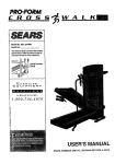
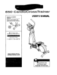
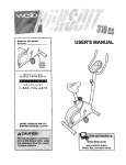
Model No. 831.299412
Serial No.
PRO'FORA4
The serial number is found in the location
shown below. Write the serial number in
the space above for future reference.
395CW
USER'S MANUAL
EXERCISE
V
EQUIPMENT
HELPLINE!
1-800-736-6879
%
/
J
SEARS, ROEBUCK AND CO.
HOFFMAN ESTATES, IL 60179
CAUTION
Read all precautions and Instructions In this manual before
using this equipment. Save this
manual for future reference.
www.proform.com
new products, prizes,
fitness tips, and much more!
TABLE OF CONTENTS
IMPORTANT PRECAUTIONS
BEFORE YOU BEGIN
ASSEMBLY
2
4
5
7
10
12
OPERATION AND ADJUSTMENT
HOW TO FOLD AND MOVE THE TREADMILL
TROUBLE-SHOOTING
.
CONDITIONING
GUIDELINES
ORDERING REPLACEMENT
FULL 90 DAY WARRANTY
14
Back Cover
.Back Cover
PARTS
Note An EXPLODED DRAWING and a PART LIST are attached
EXPLODED DRAWING and PART LIST for future reference
IMPORTANT
m the center of th_s manual.
Save the
PRECAUTIONS
WARNING:
To reduce the risk of bums, fire, electric shock, or Injury to persons, read the
following Important precautions end Information before operating the treadmill.
1. It Is the responsibility of the owner to ensure
that all users of this treadmill are adequately
Informed of all warnings and precautions.
2. Use the treadmill only as described.
3. Place the treadmlU on a level surface, with
eight feet of clearance behind It. Do not place
the treadmill on a surface that blocks any air
openings. To protect the floor or carpet from
damage, place a mat under the treadmill.
9. Wear appropriate exercise clothing when
using the treadmill. Do not wear loose clothing that could become caught In the treadmill.
Athletic support clothes are recommended for
both men and women. Always wear athletic
shoes. Never use the treadmill with bare feet,
wearing only stockings, or In sandals.
10. When connecting the power cord (see page 7),
plug the power cord into a surge suppressor
(not Included) and plug the surge suppressor
Into a grounded circuit capable of carrying 15
or more amps. No other appliance should he
on the same circuIt. Do not use an extension
cord.
4. Keep the treadmill Indoors, away from moisture and dust. Do not put the treadmill In a
garage or covered patio, or near water.
11. Use only a single-outlet surge suppressor
that Is UL 1449 listed as a transient voltage
surge suppressor (TVSS). The surge suppressor must have a UL suppressed voltage rating
of 400 volts or leas and a minimum surge dissipation of 450 joules. The surge suppressor
must be electrically rated for 120 volts AC and
15 amps. To purchase a surge suppressor,
sea your local PROFORM dealer or call 1-800366-7278 and order part number 146148.
5. Do not operata the treadmill where aerosol
products are used or where oxygen is being
administered.
6. Keep children under the age of 12 and pets
away from the treadmill at all times.
7. The treadmill should be used only by persons
weighing 250 pounds or less.
8. Never allow more than one person on the
treadmill at a time.
12. Keep the power cord and the surge suppressor away from heated surfaces.
2
13.Nevermovethewalkingbeltwhilethepower
Isturnedoff. Donot operatethe tresdmUlIf
thepowercordor plugIsdamaged,
or If the
treadmillIs notworkingproperly.(SeeBEFOREYOUBEGINonpage4 if thetreadmill
is notworkingproperly.)
14.Neverstartthetreadmillwhileyouare
standingonthewalkingbelt.Alwayshold
the handrailswhileusingthetreadmill.
15.ThetreadmillIscapableofhighspeeds,
Adjustthespeedin smallincrementsto
avoidsuddenjumpsin speed.
pounds (20 kg) to raise, lower, or move the
treadmill.
18. When folding or moving the treadmill, make
sure that the storage latch Is fully closed.
19. Inspect and tighten all parts of the treadmill
every three months.
20. Never drop or insert any object into any
opening.
21DANG ER: Always
unplug the
power
cord Immediately after use, before cleaning
the treadmill, and before performing the
maintenance and adjustment procedures described in this manual. Never remove the
motor hood unless instructed to do so by an
authorized service representative. Servicing
other than the procedures in this manual
should be performed by an authorized service representative only.
16. Never leave the treadmill unattended while It
is running. Always remove the key and unplug the power cord when the treadmill is not
In use.
17. Do not attempt to raise, lower, or move the
treadmill until It Is properly assembled. (See
ASSEMBLY on pages 5 and 6. and HOW TO
FOLD AND MOVE THE TREADMILL on page
10.) You must be able to safely lift 45
22. This treadmill Is intended for In-home use
only. Do not use this treadmill In any commercial, rental, or institutional setting.
WARNING:
Before beginning this or any exercise program, consult your physician. This
Is especially Important for persona over the age of 35 or persons with pre-existing health problems.
Read all Instructions before using. SEARS assumes no responsibility for personal Injury or property
damage sustained by or through the use of this product.
SAVETHESEINSTRUCTIONS
The decal shown below has been placed on your treadmill. If the
decal Is missing, or if it Is not legible, please call our toll-free
HELPLINE to order a free replacement decal (see the back cover
of this manual). Apply the decal in the location shown.
Note: Decal is shown at 38% of actual size.
3
BEFORE YOU BEGIN
Thank you for selecting the new PROFORM ®395CW
treadmill. The 395CW treadmill combines advanced
technology with innovativedesign to let you enjoy an
excellent form of cardiovascularexercise in the convenience and privacyof your home. And when you're not
exercising, the unique395CW can be folded up, requiring lessthan half the floor space of othertreadmills.
Monday through Saturday, 7 a.m. until7 p.m. Central
Time (excluding holidays). To help us assistyou,
please note the productmodel number and serial number before calling. The model number of the treadmill
is 831.299412. The serial number can be found on a
decal attached to the treadmill(see the front cover of
this manual for the location).
For your benefit, read this manual carefully before
using the treadmill. If you have additionalquestions,
please call our toll-free HELPLINE at 1-800-736-6879,
Before reading further, please review the drawing
below and familiarize yourself with the parts that are
labeled.
Console
Water Bottle Holder
Upper Body Arms-
Handrail
Storage Latch
- Upright
Walking Belb
RIGHT SIDE
Circuit
Breaker
Power
Cord
Rear Roller
AdjustmentBolts
Cushioned Walking Platform
for maximum exercise comfort
BACK
Leg
4
ASSEMBLY
Assembly requires two people. Set the treadmill in a cleared area and remove all packing materials. Do not
dispose of the packingmaterials untilassembly is completed.Assembly requires the Included allen wR_n,_
and your own phillips screwdriver _=======[_
and wire cutters _.
Note: The underside of the treadmill walking belt is coated with high-performance lubricant.During shipping,a
small amount of lubricant may be transferred to the top of the walking belt or the shipping carton. This is a normal
condition and does not affect treadmill performance. If there is lubricant on top of the walking belt, simplywipe off
the lubricant with a soft cloth and a mild, non-abrasive cleaner.
Extension Leg Screw (53)-2
Handrail Screw (33)-2
1. Cut the plastic tie off the side of the treadmill.
With the help of a second person, carefully raise the
Uprights (11) until the treadmill is in the position shown.
2. Insert one of the Extension Legs (34) intothe treadmill
as shown. (Note: It may be helpfulto tip the Uprights
[11] in the direction shownby the arrow as you insert
the Extension Leg.) Make sure that the Base Pad (40) is
on the indicatedside of the Extension Leg. Attach the
Extension Leg with an Extension Leg Screw (53). Be
sure to push on the head of the Extension Leg
Screw while tightening it.
Attach the other Extension Leg (34) in the same way.
5
Latch Screw (35)-2
3. Insert one of the Handrails (1) into the tube at the upper
end of the right Updght (11).
1\
4. Align the hole in the Handrail (1) with the indicatedhole
in the Upright (11). Tighten a Handrail Screw (33) intothe
Uprightand the Handrail at the angle shown in drawing
4b. It may be helpfulto lift up and push down on the
Handrail as you thread the Handrail Screw.
4b
4
--33
" --11
Attach the other Handrail to the left Upright (not shown).
Bottom View
5. Attach the Storage Latch (14) to the left Upright(11) with
two Latch Screws (35). Be careful not to overtlghten
the Latch Screws.
11j
"_35
14
6. Make sure that all parts are tightened before you use the treadmill. Keep the included allen wrench in a
secure place. The allen wrench is used to adjust the walking belt (see page 13). To protectthe floor or carpet,
place a mat under the treadmill.
6
OPERATION
AND ADJUSTMENT
THE PERFORMANT LUBE
TM
WALKING BELT
Your treadmill features a walking belt coated with
PERFORMANT
LUBE TM, a high-performance
lubricant.
IMPORTANT:
Never apply silicone spray or other
substances to the walking belt or the walking platform. Such substances will deteriorate
the walking
belt and cause excessive
wear,
HOW TO PLUG IN THE POWER
This product is for use on a nominal 120-volt circuit,
and has a grounding plug that looks like the plug illustrated in drawing 1 below. A temporary adapter that
looks like the adapter illustrated in drawing 2 may be
used to connect the surge suppressor to a 2-pole
receptacle as shown in drawing 2 if a properly
grounded outlet is not available.
CORD
,//_l-_Grounded
DANG ER:
connection
Improper
of the equipment-grounding conductor can
result In an Increased risk of electric shock.
Check with a qualified electrician or serviceman If you are In doubt as to whether the
product Is properly grounded. Do not modify
the plug provided with the product--if It will
not fit the outlet, have a proper outlet
installed by a qualified electrician.
i
ding
Grounded
Outlet
[_Grounded
Your treadmill, like any other type of sophisticated
electronic equipment, can be seriously damaged by
sudden voltage changes in your home's power.
Voltage surges, spikes, and noise interference can
result from weather conditions or from other appliances
being turned on or off. To decrease the possibility
of
your treadmill being damaged, always use a surge
suppressor with your treadmill (see drawing 1 at
the right).
To purchase a surge suppressor,
PROFORM dealer or call toll-free
Outlet Box
see your local
1-800-366-7278
and order part number 146148. Use only a singleoutlet surge suppressor that is UL 1449 listed as a
transient voltage surge suppressor (TVSS). The surge
suppressor must have e UL suppressed voltage rating
of 400 volts or less and a minimum surge dissipation of
450 joules, The surge suppressor must be electrically
rated for 120 volts AC and 15 amps.
This product must be grounded. If it should malfunction or break down, grounding providesa path of least
resistance for electriccurrent to reduce the risk of electric shock. This product is equipped with a cord having
an equipment-groundingconductor and a grounding
plug. Plug the power cord into a surge suppressor,
and plug the surge suppressor into an appropriate
outlet that is properly Installed and grounded in
accordance with all local codes and ordinances.
Important: The treadmill is not compatible with
GFCl-equipped outlets.
II / "J
(3rounding
Plug'_
Outlet Box
Adapter
&_%_-_l
^
Surge _uppressor
The temporary adapter should be used only until a
properly grounded outlet (drawing 1) can be installed
by a qualified electrician.
The green-colored rigid ear, lug, or the like extending
from the adapter must be connected to a permanent
ground such as a properly grounded outlet box cover.
Whenever the adapter is used it must be held in place
by a metal screw, Some 2-pole receptacle outlet box
covers are not grounded. Contact a qualified electrician to determine if the outlet box cover is
grounded before using an adapter.
CONSOLE
DIAGRAM
TRAINING
ZONES
PERFORMANCE
TIME / DISTANCE
©
CALS
J F-CALS
FAST
/ SPEED
ON / RESET
WARM UP
COOL DOWN
AEROBIC
SLOW
!_
_
_'._. PRESS ON I RESET BUTTON
_-
RESffr/SET
poWER
_EEO
Note: If there is a thin sheet of clear
plastic on the face of the console,
remove it before operating the console.
INCLINE
CAUTION: Before
operating
console, read the following precautions.
STOP
SPEED CONTROL
the
- Do not stand on the walking belt when turning on the power.
• Always wear the clip (see the drawing at
the lower right) while using the treadmill,
When the key is removed from the console,
the walking belt will stop.
Battery
Cover Tab
• Adjust the speed In small Increments_
Close the battery cover, push up on the battery cover
tab, and then push the tab forward as shown in the
inset drawing. Be sure that the tab locks into place.
• The training zones marked beside the
speed control are general guidelines only.
See page 14 for more information.
STEP-BY-STEP CONSOLE OPERATION
• To reduce the possibility of electric shock,
keep the console dry. Avoid spilling liquids
on the console and use only a sealable
water bottle.
Before operating the console, make sure that the
power cord is properly plugged in. (See HOW TO
PLUG IN THE POWER CORD on page 7.)
Stand on the foot rails of the
treadmill. Find the clip attached to the key and slide
the clip onto the waistband
of your clothing. Next, insert
the key into the console.
Test the clip by carefully taking a few steps backward until the key is pulled from the console. If the
key is not pulled from the console, adjust the position of the clip as needed.
BATFERY INSTALLATION
The console requires two "AA" batteries (not included). Alkaline batteries are recommended. Open
the battery cover as shown in the drawing at the upper
right, Insert two batteries into the battery compartment,
making sure that the negative (-) ends of the batteries
are touching the springs in the battery compartment.
8
Followthestepsbelowtooperatetheconsole.
B
TIME/DISTANCE display--This display
shows the elapsed time
¥Rt
and distance that you
I
Arro_p B
have walked or run, in
TIME / DISTANCE
miles. Every seven seconds, the display will
change from one number to the other, as shown by
the arrows in the display.
B InsertthekeyIntothepowerswitch.
Inserting the key will
©
not turn on the displays. The displays will
turn on when the
ON/RESET button is
pressed or when the
walking belt is started.
Note: If you just
installed batteries, the displays willalready be on.
la
B
CALS/FAT CALS/
SPEED display--This
display shows the approximate numbers of
calories and fat calories
you have burned. (See
FAT BURNING on
Reset the speed control.
Slide the speed control
down to the RESET
position.Note: Each
time the walking belt
is stopped, the speed
control must be
moved to the RESET
position before the
walking belt can be
restarted.
WARM Up
SLOW
RESET •
Arrow\
CALS / F-CALS / SPEED
page 14.) In addition,the display shows the speed
of the walking belt, in miles per hour. Every seven
seconds, the display will change from one number
to the next, as shown by the arrows in the display.
< STOP
To reset the displays at
any time, press the
ON/RESET button.
Start the walking belt.
After you have moved the speed controlto the
RESET position,slowlyslide it upward until the
walking belt begins to move at slow speed.
Carefully step onto the walking belt and begin exercising. Change the speed of the walking belt as
desired by slidingthe speed control.
r_
Adjust the Incline of the treadmill as desired.
To change the inclineof
the treadmill, press the
top or bottom of the incline control untilthe
desired incline level is
reached.
f
II ,=,14II-----Ir-r-_ II
LL_J._ I Up
• ...,.,d
when you are finished exercising, stop the
walking belt and remove the key.
Step onto the foot rails, stop the walking belt and
remove the key from the console. The displayswill
turn off about five minutesafter the key is removed.
Note: Any Ume that the walking belt Is stopped
and the ON/RESET button Is not pressed for
five minutes, the displays will automatically
turn off In order to conserve the batteries.
To stop the walking belt, step onto the foot rails
and slide the speed controlto the RESET position.
B
Monitor your progress with the two displays.
I
Ii_ II-----
9
HOW TO USE THE UPPER BODY ARMS
Upper Body
As you exercise on the treadmill, you can hold either the
handrailsor the upper body arms. The upper body arms are
designed to exercise your arms, shoulders, and back for a
total body workout. Hold one upper body arm with each
hand, and move them forward and back as you walk on the
treadmill.
To vary the intensityof your upper body exercise, the resistance of the upper body arms can be adjusted.To increase
the resistance, turn the resistance knobsclockwise;to decrease the resistance, turn the knobscounterclockwise.
HOW TO FOLD AND MOVE THE TREADMILL
HOW TO FOLD THE TREADMILL FOR STORAGE
Before folding the treadmill, unplugthe power cord. Caution:
You must be able to safely lift 45 pounds (20 kg) In order
to raise, lower, or move the treadmill.
1. Hold the treadmill with your hands in the locationsshown
at the right.To decrease the possibility of Injury, bend
your legs and keep your back straight. As you raise
the trsadmlll, make sure to lift with your legs rather
than your back. Raise the treadmillabout halfway to the
vertical position.
2. Move your right hand to the positionshown and hold the
treadmillfirmly. Raise the treadmill untilthe storage latch
closes over the catch. Make sure that the storage latch
Is fully engaged over the catch.
To protect the floor or carpet from damage, place a
mat under the treadmill. Keep the treadmill out of
direct sunlight. Do not leave the treadmill in the storage position In temperatures above 85" Fahrenheit.
10
HOW TO MOVE TIIE TREADMILL
Before moving the treadmill, convert the treadmillto the storage position as described above. Make sure that the storage latch Is closed fully over the catch.
1. Hold the upper ends of the handrails. Place one foot on
the base as shown.
2. Tilt the treadmill back until it rollsfreely on the front
wheels. Carefully move the treadmillto the desired location. To reduce the risk of Injury, use extreme caution
while moving the treadmill. Do not move the treadmill
over an uneven surface.
Base
3. Place one foot on the base, and carefully lower the treadmill until it is resting in the storage position.
els
HOW TO LOWER THE TREADMILL FOR USE
1. Hold the upper end of the treadmill with your right hand
as shown. Using your left thumb, press the storage latch
and hold it. Pivot the treadmill until the frame and foot rail
are past the storage latch.
Latch
/
2. Hold the treadmillfirmly with both hands, and lower the
treadmillto the floor. Do not drop the treadmill frame to
the floor. To decrease the possibility of Injury, bend
your legs and keep your back straight.
11
TROUBLE-SHOOTING
Most treadmill problems can be solved by following the simple steps below. Find the symptom that
applies, and follow the steps listed. If further assistance Is needed, call our toll-free HELPLINE at
1-800-736-6879, Monday through Saturday, 7 a.m. until 7 p.m. Central Time (excluding holidays).
1. SYMPTOM: THE POWER DOES NOT TURN ON
a. Make sure that the power cord is plugged into a surge suppressor,and that the surge suppressoris plugged
into a properlygrounded outlet (see page 7). Use only a single-outletsurge suppressorthat is UL 1449
listed as a transient voltage surge suppressor(TVSS). The surge suppressor must have a UL suppressed
voltage rating of 400 volts or less and a minimumsurge dissipationof 450 joules. The surge suppressor
must be electricallyrated for 120 volts AC and 15 amps. Important:The treadmill is not compatiblewith
GFCI-equipped outlets.
b. After the power cord has been plugged in, make sure that the key is fully inserted intothe console.
c. Check the circuitbreaker located on the treadmillnear the
power cord. If the switch protrudes as shown, the circuit
breaker has tripped. To reset the circuitbreaker, wait for five
minutesand then press the switch back in.
Tripped
Reset
Tdpped
Reset
2. SYMPTOM: THE POWER TURNS OFF DURING USE
a. Check the circuit breaker located on the treadmillframe near the power cord (see 1. c. above). If the circuit
breaker has tripped, wait for five minutes and then press the switch back in.
b. Make sure that the power cord is plugged in.
c. Remove the key from the console. Reinsert the key fully intothe console.
d. If the treadmillstill will not run, please call our toll-free HELPLINE.
3. SYMPTOM: THE DISPLAYS OF THE CONSOLE DO NOT FUNCTION PROPERLY
a. Check the batteries in the console. See BA'I-rERY INSTALLATION on page 8. Most problems are the result
of drained batteries.
b. Remove the key from the console and UNPLUG THE POWER
CORD. Remove the two Resistance Bracket Bolts(78), Washers
(39) and Star Washers (87) from the left Upright (11). Remove
the screws from the hood. Carefully remove the hood.
Locate the Reed Switch (44) and the Magnet (45) on the left side
of the Pulley (50). Turn the Pulley untilthe Magnet is aligned with
the Reed Switch. Make sure that the gap between the Magnet
and the Reed Switch Is about 1/8". If necessary, loosen the
Screw (33) and move the Reed Switch slightly.Retightenthe
Screw. Re-attach the hood first, then the left Upper Body Arm
assembly. Run the treadmill for a few minutesto check for a correct speed reading.
12
_- --50
Top
View
4. SYMPTOM: THE WALKING BELT SLOWS WHEN WALKED ON
a. Use only a UL-listedsurge suppressor, rated at 15 amps, with a 14-gauge cord of five feet or less in length.
b. If the walking belt is overtightened, treadmillperformance may
decrease and the walking belt may be permanentlydamaged.
Remove the key and UNPLUG THE POWER CORD. Using the
allen wrench, turn both rear roller adjustmentbolts counterclockwise, 114of a turn. When the walking belt is properlytightened,
you shouldbe able to lift each side of the walking belt 2 to 3
inches off the walking platform.The center of the walking belt
shouldjust touchthe walking platform.Be carefulto keep the
walking belt centered. Plug in the power cord, insertthe key and
run the treadmillfor a few minutes. Repeat until the walking belt
is properly tightened.
Rear Roller AdjustmentBolts
c. If the walking belt still slows when walked on, please call our toll-free HELPLINE.
5, SYMPTOM: THE WALKING BELT IS OFF-CENTER
a. If the walking belt has shifted to the left, first remove the key
and UNPLUG THE POWER CORD. Using the allen wrench,
turn the left rear rolleradjustment bolt clockwise, and the right
bolt counterclockwise,1/4 of a turn each. Be careful not to overtighten the walking belt. Plug in the power cord, insertthe key
and run the treadmill for a few minutes. Repeat until the walking
belt is centered.
a
b. If the walking belt has shifted to the right, first remove the
key and UNPLUG THE POWER CORD. Using the allen wrench,
turn the left rear rolleradjustment boltcounterclockwise,and the
right bolt clockwise, 1/4 of a turn each. Be careful not to overtighten the walking belt. Plug in the power cord, insertthe key
and run the treadmill for a few minutes. Repeat until the walking
belt is centered.
c. If the walking belt slips when walked on, first remove the key
and UNPLUG THE POWER CORD. Using the allen wrench,
turn both rear roller adjustment belts clockwise, 1/4 of a turn.
When the walking belt is correctly tightened, you shouldbe able
to lift each side of the walking belt 2 to 3 inchesoff the walking
platform. Be careful to keep the walking belt centered. Plug in
the power cord, insertthe key and run the treadmillfor a few
minutes. Repeat untilthe walking belt is properlytightened.
6. SYMPTOM: ONE OF THE UPPER BODY ARMS SQUEAKS DURING USE
a. Correctingthis problem requires a small amount of white marine grease, available at most hardware stores.
Turn the Resistance Knob (98) counterclockwiseuntil it can be
removed. Remove the ResistanceCone (93) and the Upper
Body Arm (89), along with the 3/8" Washers (57), Spring Washer
(95), Thrust Washers (96), and Thrust Bearing (97). (Note: If the
Resistance Sleeve [92] comes out of the Resistance Bracket
[91], press it back in.) Apply a thin layer of white marine grease
to the outer surface of the Resistance Cone (93). Reattach all
parts in the order shownat the right.
13
91
92
CONDITIONING
GUIDELINES
trainingzone. It may also be helpful to set the speed
controlon the console to FAT BURN to help you maintain the proper intensitylevel. (See page 9.)
Aerobic Exercise
If your goal is to strengthen your cardiovascularsystem, your exercise must be "aerobic."Aerobicexercise
is activitythat requires large amounts of oxygen for
prolongedperiodsof time. This increasesthe demand
on the heart to pump blood to the muscles, and on the
lungsto oxygenate the blood. For aerobic exercise,
adjust the speed and inclineof the treadmill untilyour
heart rate is near the highest number in your training
zone. It may also be helpfulto set the speed controlon
the console to AEROBIC to help you maintain the
properintensity level. (See page 9.)
The following guidelineswill help you to plan your exercise program. Remember--these are general guidelines only. For more detailed exercise information,obtain a reputable book or consultyour physician.
EXERCISE INTENSITY
Whether your goal is to burn fat or to strengthen your
cardiovascularsystem, the key to achieving the desired results is to exercise with the proper intensity.
The proper intensity level can be found by using your
heart rate as a guide. The chart below shows recommended heart rates for fat burning and aerobic exercise.
High Performance Athletic Conditioning
If your goal is high performance athletic conditioning,
set the speed control on the console to PERFORMANCE to help you maintain the proper intensity level.
(See page 9.) Note: During the first few weeks of your
exercise program, keep your heart rate near the low
end of your training zone.
HEARTRATETRAININGZONE
C
AGE
m_,,
r, .....
• ....
HOW TO MEASURE YOUR HEART RATE
.4=
2O
30
C 40
:'"
_:
C50
(60
60
To measure your
heart rate, stop exercisingand place
two fingers on
your wrist as
shown. Take a sixsecond heartbeat
count, and multiply
the result by ten to
find your heart rate. (A six-second count is used because your heart rate drops quicklywhen you stop exercising.) If your heart rate is too high or too low, adjust
the speed or inclineof the treadmillaccordingly.
._
,,
•
.•
7O
80
_
__
To find the proper heart rate for you, first find your age
on the left side of the chart (ages are rounded off to
the nearest ten years). Next, find the three numbers to
the right of your age. The three numbers are your
"training zone." The lower two numbers are recommended heart rates for fat burning; the higher number
is the recommended heart rate for aerobic exercise.
WORKOUT GUIDELINES
A well-rounded workout includesthe followingthree
importantpads:
Fat Burning
To burn fat effectively,you must exercise at a relatively
low intensitylevel for a sustained period of time. During
the first few minutesof exercise, your body uses easily
accessible carbohydratecalories for energy. Only after
the first few minutesdoes your body begin to use
stored fat calories for energy. If your goal isto burn fat,
adjust the speed and inclineof the treadmilluntilyour
heart rate is near one of the lower two numbers in your
A Warm-up
Start each workout with 5 to 10 minutesof stretching
and light exercise (see SUGGESTED STRETCHES on
page 15). A proper warm-up increases your body
temperature, heart rate, and circulationin preparation
for exercise.
14
Training Zone Exercise
to cool down. This will increase the flexibility of your
musclesand willhelp to prevent post-exemiseproblems.
After warming up, increase the intensityof your exercise until your pulse is in your training zone for 20 to
60 minutes. (During the first few weeks of your exercise program, do not keep your pulse in your training
zone for longer than 20 minutes.) Breathe regularly
and deeply as you exercise--never hold your breath.
Exerclse Frequency
To maintain or improve your condition,complete three
workouts each week, with at least one day of rest between workouts. After a few months, you may complete up to five workouts each week if desired.
A Cool-down
The key to success is to make exercise a regular and
enjoyable part of your everyday life.
Finish each workout with 5 to 10 minutes of stretching
SUGGESTED STRETCHES
The correct form for several basic stretches is shown at the
right. Move slowly as you stretch--never bounce.
1. Toe Touch Stretch
Stand with your knees bent slightlyand slowlybend forward
from your hips. Allow your back and shouldersto relax as you
reach down toward yourtoes as far as possible. Hold for 15
counts, then relax. Repeat 3 times. Stretches: Hamstrings,
back of knees, and back.
2. Hamstring _retch
Sit with one leg extended. Bringthe sole of the oppositefoot
toward you and rest it against the inner thigh of yourextended
leg. Reach toward your toes as far as possible. Hold for 15
counts, then relax. Repeat 3 times for each leg. Stretches:
Hamstrings, lower back, and groin.
3. Calf/Achilles Stretch
With one leg in front of the other, reach forward and place your
hands against a wall. Keep your back leg straight and your
back foot flat on the floor. Bend your front leg, lean forward and
move your hipstoward the wall. Hold for 15 counts, then relax.
Repeat 3 times for each leg. To cause further stretchingof the
achilles tendons, bend your back leg as well. Stretches:
Calves, achilles tendons, and ankles.
4, Quadrlceps Stretch
With one hand against a wall for balance, reach back and
grasp one foot with yourother hand. Bring your heel as close
to your buttocksas possible. Hold for 15 counts, then relax.
Repeat 3 times for both legs. Stretches: Quadriceps and hip
muscles.
5. Inner Thigh Stretch
Sit with the soles of your feet together and your knees outward.
Pull your feet toward your groinarea as far as possible. Hold
for 15 counts, then relax. Repeat 3 times. Stretches:
Quadriceps and hip muscles.
15
PART LIST-- Model No. 831.299412
Key No.
Qty.
1
2
3
4
5
6
7
8
9
10"
11
12
13
14
15
16
17
18
19
20*
21
22
23
24
25
26
27
28
29
30
31
32
33
34
35
36
37
38
39
40
41
42
43
44
45
46
47
48
49
50
51
52
53
2
1
2
1
2
1
1
1
1
1
1
1
15
1
1
7
1
1
1
1
1
4
1
1
22
1
1
1
1
1
2
1
2
2
4
2
2
6
15
4
2
1
1
1
1
1
1
4
4
1
1
2
2
Description
Handrail
Key/Clip
Incline Leg Pivot Bolt
Battery Cover
Foot Rail
Lift Motor
Rear Roller
Speed Potentiometer
Speed Control Knob
Console Assembly
Upright Base
Motor Belt
Small Screw
Storage Latch
Frame Pivot Spacer (Left)
8" Cable Tie
Incline Leg Pivot Nut
PuUey/Flywheel/Fan
Motor
Motor/Pulley/Flywheel/Fan
Wire Harness
Belt Guide Screw
Motor Hood
Hood Shield
Small Screw
Controller
Motor Swivel Bolt
Motor Tension Nut
Motor Tension Star Washer
Motor Tension Washer
Motor Tension Bolt
InclineStop Bracket
Handrail Screw
Extension Leg
Latch Screw
Wheel Bolt
Wheel
Wheel Nut/Lift Nut
Washer
Base Pad
Handrail Cap
Latch Catch
Reed Switch Clip
Reed Switch
Magnet
Console Base
Frame Pivot Spacer (Right)
PlatformScrew
Isolator
Front Roller/Pulley
Front Roller Adj. Bolt
InclineWheel
Extension Leg Screw
Key No.
54
55
56
57
58
59
60
61
62
63
64
65
66
67
68
69
70
71
72
73
74
75
76
77
78
79
80
81
82
83
84
85*
86
87
88
89
90
91
92
93
94
95
96
97
98
#
#
#
#
RlOOOA
Qty.
1
1
1
6
2
1
1
2
4
3
1
2
4
1
1
1
9
1
1
4
1
1
2
2
4
2
2
1
1
2
1
2
1
4
2
1
2
2
2
2
1
2
4
2
2
1
1
1
1
Description
Power Cord
Power Cord Grommet
Circuit Breaker
318"Washer
Frame Pivot Bolt
Latch Decal
Motor Belly Pan
Cable Tie Clamp
Rear PlatformScrew
Releasable Tie
Choke
Belt Guide
Belly Pan Fastener
Walking Belt
Walking Platform
Belly Pan
ElectronicsScrew
InclineWire Harness
UprightGrommet
IsolatorScrew
Allen Wrench
Frame
Front Endcap
InclineWheel Bolt
Resistance Bracket Bolt
InclineWheel Nut
Front Hood Screw
Ground Wire
Incline Leg
Rear RollerAdj. Bolt
Rear Endcap
Extension Leg Assembly
Incline Motor Bolt
Star Washer
Foam Grip
Left Upper Body Arm w/Foam Grip
Resistance Bolt
Resistance Bracket
Resistance Sleeve
Resistance Cone
Right Upper Body Arm w/Foam Grip
Spring Washer
Thrust Washer
Thrust Bearing
Resistance Knob
14"White Wire, M/F
5" Black Wire, 2 Ring
8" White Wire, Pigtail
User's Manual
* Includesall parts shown in the box
# These parts are not illustrated
EXPLODED
DRAWING--
Model No. 831,29941 2
9O
48
97
57
68
9O
31
R1000A
SEARS
The model number and serial number of your PROFORM ®395CW
treadmillare listedon a decal attached to the frame. See the front
cover of this manual to find the locationof the decal.
Model No. 831.299412
QUESTIONS?
All replacement parts are available for immediate purchase or
special order when you visityour nearest SEARS Service Center.
To request service or to order parts by telephone, call the toll-free
numbers listedat the left.
If you find that:
• you need help assembling or
operating the PROFORM
395CW treadmill
• a part Is missing
When requestinghelp or service, or orderingparts, please be
prepared to provide the followinginformation:
• The NAME OF THE PRODUCT (PROFORM ®395CW treadmill)
• or you need to schedule repair
service
call our toll-free HELPLINE
• The MODEL NUMBER OF THE PRODUCT (831.299412)
• The KEY NUMBER AND DESCRIPTION OF THE PART (see the
EXPLODED DRAWING and PART LIST included in this manual
1-800-736-6879
Monday-Saturday, 7 am-7 pm
Central Time (excluding holidays)
REPLACEMENT
PARTS
If parts become worn and need
to be replaced, call the following
toll-fR=e number
1-800-FON-PART
(1-800-366-7278)
FULL 90 DAY WARRANTY
For 90 days from the date of purchase, if failure occurs due to defect in material or workmanship in this
SEARS TREADMILL EXERCISER, contact the nearest SEARS Service Center throughoutthe United
States and SEARS will repair or replace the TREADMILL EXERCISER, free of charge.
This warrantydoes not apply when the TREADMILL EXERCISER is used commerciallyor for rental purposes.
This warranty gives you specificlegal rights,and you may also have other rightswhich vary from state
to state.
SEARS, ROEBUCK AND CO., DEPT. 81"/_/A, HOFFMAN ESTATES, IL 60179
Part No. 168422 R1000A
Printed in Canada © 2000 Sears, Roebuck and Co.