1
PRO "FORM
PERFORMANCE
®
TREADMILL
Model No. 831.297062
Serial No.
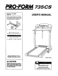
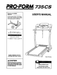
The serial numberis foundin the location
shown below. Write the serial numberin
the space above for future reference,
USER'S MANUAL
Serial Number
Decal
EXERCISE
EOU
I
PM
ENT
HELPLINE!
1-800-736-6879
SEARS, ROEBUCK AND CO., HOFFMAN ESTATES, IL 60179
TABLE OF CONTENTS
IMPORTANT PRECAUTIONS .................................................................
BEFORE YOU BEGIN .......................................................................
ASSEMBLY ...............................................................................
OPERATION AND ADJUSTMENT .............................................................
HOW TO FOLD AND MOVE THE TREADMILL ..................................................
TROUBLE-SHOOTING .....................................................................
CONDITIONING GUIDELINES ...............................................................
ORDERING REPLACEMENT PARTS ..................................................
FULL 90 DAY WARRANTY ...........................................................
2
4
5
7
10
12
14
Back Cover
Back Cover
Note: An EXPLODED DRAWING and a PART LIST are attached in the center of this manual. Save the
EXPLODED DRAWING and PART LIST for future reference.
IMPORTANT
PRECAUTIONS
following Important precautions and Information before operating the treadmill.
1. It ls the responelbllity of the owner to ensure
that ell users of this treadmill are adequately
Informed of all warnings and precautions.
9. Wearapproprlateexerclseclothlngwhen
using the treadmill. Do not wear loose cloth-
2. Use the treadmill only as deacrlbed.
shoes. Never use the treadmill with bare feet,
wearing only stockings, or in sandals.
3, Place the treadmill on a level surface with 8
feet of clearance behind It. Do not place the
treadmill on a surface that blocks any air
openings. To protect the floor or carpet from
damage, place a mat under the treadmill.
10, When connecting the power _
(see page 7),
Into a grounded circuit _ble
nf cerrylng 15
or more amps. No other appliance should he
on the same circuit_ Do not use an e_tenelon
cord.
4. Keep the treadmill indoors, away from mole-
5. Do not operate the treadmill where earosul
products are used or where oxygen Is being
admlnlatered.
11. Usa only a single-outlet surge suppressur
that is UL 1449 listed as a tranelent voltage
surge suppressor (TYSS). _
surge suppressor must have a UL suppressed voltage rating
of 400 volts or _
and a minimum surge disstpetlon of 450 joules. The surge suppressor
must he electrically rated for 120 volts AC and
15 amps,
6. Keep children under the age of 12 and pets
away from the treadmill at ell times.
7. The t_mill
should be used only by persons
weighing 250 pounds or leas.
12. Keep the power cord and the surge suppressor away from heated surfaces.
8. Never allow more than one person on the
treadmill at a time.
2
Is turned off. DO not oparate _
besdmlll If
sure that the storage latch Is fully closed.
19. Inspect and tighten all parts of the troadmlll
FORE YOU BEGIN on page 4 if the treadmill
standing on the walking hell Always hold
the handrails while using the treadmill.
15. The treadmill Is capable of h!gh speeds
Adjust the speed in small Increments to
avoid sudden jumps In speed.
plug the power _
not In use.
21. This treadmill is Intended for in-home use
only. DO not use this treadmill In any commerclsl, rental, or Institutional setting,
when the treadmill _
described In this manual. Never remove the
motor hood unless Instructed to do so by an
authorized service representatlve_ Servlclog
other than the procedures In this manual
should be performed by an authorized ser-
17. DO not attempt to raise, lower, or move the
treadmill untg It is properly assembled. (See
must be abe to safely lift 45 pounds (20 kg)
to raise, lower, or move the treadmill.
• WARNING:
,_oro beginning th s or any exercise program, consu t your phys c an. This
is especially Important for parsons over the age of 35 or persons wIth preexisting health problems.
Read all Instructions before using. SEARS assumes no responsibility for personal Injury or property
damage sustained by or through the use of this product.
The decal shown at the right has been
placed on your treadmill. If the decal is
missing, or If it Is not legible, please
call our toll-free HELPLINE to order a
free replacement decal (see the back
cover of this manual). Apply the decal
In the location shown.
• Never allow children
on or around
treadmill.
• Storage latch must be
fully engaged before
treadmill is moved or
stored.
3
im
m
BEFORE YOU BEGIN
Thank you for selecting the new PROFORM ®J4 treadmill. The J4 treadmill combines advanced technology
with innovativedesign to let you enjoy an excellent
form of cardiovascular exercise in the convenience and
privacy of your home. And when you're not exercising,
the unique J4 can be folded up, requiring less than half
the floor space of other treadmills.
Monday through Saturday, 7 a.m. until 7 p.m. Central
Time (excludingholidays). To help us assist you,
please note the productmodel number and serial number before ca_ling.The model number of the treadmill
is 831.297062. The serial number can be found on a
decal attached to the treadmill (see the front cover of
this manual for the location).
For your benefit, read this manual carefully before
using the treadmill. If you have additional questions,
please caUour toll-free HELPLINE at 1-800-736-6879,
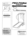
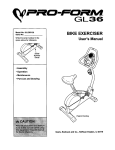
Before reading further, please review the drawing
below and familiarize yourself with the parts that are
labeled.
Console
Water BottleHolder
Bottle not included)
Upright
Walking BeltRIGHT SIDE
Foot
Circuit
Breaker
Power
Co_
Rear Roller
AdjustmentBolts
Cushioned Walking Platform
for maximum exercise comfort
BACK
lcline Leg
4
ASSEMBLY
Assembly requires two people. Set the treadmill in a cleared area and remove all packing materials. Do not
dispose of the packing materials untilassembly is completed.Assembly requires the Included allen wrench _
and your own phillips screwdriver ._=====_.
Note: The underside of the treadmill walking belt is coated with high-performancelubricant. During shipping,a
small amount of lubricant may be transferredto the top of the walking belt or the shippingcarton. This is a normal
conditionand does not affect treadmill performance. If there is lubricanton top of the walking belt, simplywipe off
the lubricant with a soft cloth and a mild, non-abrasive cleaner.
Extension Leg Screw (53)-4
Latch Screw (35)-2
1. With the help of a second person, carefully raise the
treadmillto the upright position.As a second person tips
the treadmillto one side slightlyand holds it, insertone
of the Extension Legs (34) intothe treadmillas shown.
Make sure that the Base Pad (40) is on the indicated
side of the Extension Leg. Attach the Extension Leg
with an Extension Leg Screw (53). Be sure to push on
the head of the Extension Leg Screw while tightening It.
34
Attach the other Extension Leg (not shown)as described
above.
With the help of a second person, carefully lower the
treadmillso that both Extension Legs (34) are resting
flat on the floor.
40
2. Hold the treadmill firmly with both hands, and lower the
treadmill to the floor. To decrease the possibility of
injury, bend your legs and keep your back straight.
I
5
3. Hold one of the Handrails (1) at an angle as shown and
insert the upper end into the right Upright (11) as far as
possible. Keep the lower end of the Handrail away from
the treadmill to avoid scratching the finish.
Next, rotate the lower end of the Handrail (1) to the position shown by the dotted line. Note: It may be necessary
to pull back on the lower end of the Handrail in order to
positionthe Handrail against the bracket on the
Extension Leg (34).
Make sure that the hole in the bracket on the Extension
Leg (34) is aligned with the hole in the Handrail (1). Ifthe
holes are not aligned, rotate the Handrail away from the
treadmilland slide the upper and of the Handrail slightly
out of the Upright(11). Then, rotate the lower end of the
Handrail back to the positionshownby the dotted line.
Repeat, if necessary, untilthe holes are aligned.
Bracket
3a.Refer to drawing3a. Make sure that the lower end of the
Handrail (1) is against the bracket on the ExtensionLeg.
Tighten an Extension Leg Screw (53) intothe bracket and
the Handrail.
3a
Attach the other Handrail (not shown) as described above.
_----Bracket
1
4. Attach the Storage Latch (14) to the left Upright (11) with
two Latch Screws (35). Be careful not to overtlghten
the Latch Screws.
5. Remove the backing from the Adhesive Clip (33). Press
the Adhesive Clip onto the right Upright(11) in the indicated location. Press the Allen Wrench (88) intothe
Adhesive Clip.
6. Make sure that all parts are tightened before you use
the treadmill. Note: The ratchet screws are factory set
and should not be adjusted.
To protect the floor or carpet, place a mat under the treadmill.
6
34
4
5
.f
Ratchet
Screws _
o
OPERATION
AND ADJUSTMENT
THE PERFORMANT LUBE TM WALKING BELT
This product is for use on a nominal 120-volt circuit,
and has a groundingplug that lookslike the plug illustrated in drawing 1 below. A temporary adapter that
looks like the adapter illustratedin drawing2 may be
used to connect the surge suppressorto a 2-pole
receptacle as shown in drawing 2 if a properly
grounded outlet is not available.
Your treadmill features a walking belt coated with
PERFORMANT LUBE TM, a high-performance lubricant.
IMPORTANT: Never apply silicone spray or other
substances to the walking belt or the walking platform. Such substances will deteriorate the walking
belt and cause excessive wear.
HOW TO PLUG IN THE POWER CORD
Grounded Outlet Box
_.J
of the equipment-grounding conductor can
result In an Increased risk of etectdc shock.
Check with a qualified electdclan or service.
man ff you are In doubt as to _her
the
product Is properly grounded. Do not modify
the plug provided with the product--if it wUl
not fit the outlet, have a proper outlet
Installed by a qualified electrician.
_
Surge Suppressor
'_...
Grounding Pin
Grounding Pin
Grounded Outlet
Grounding Plu
2
Grounded Outlet Box
Adapter
Your treadmill, like any other type of sophisticated
electronic equipment, can be seriously damaged by
sudden voltage changes in your home's power.
Voltage surges, spikes, and noise interference can
result from weather conditions or from other appliances
being turned on or off. To decrease the possibility of
your treadmill being damaged, always use a surge
suppressor with your treadmill (see drawing I at
the right).
^
Surge _uppressor
Metal Screw
Surge suppressors are sold at most hardware stores
and department stores. Use only a single-outletsurge
suppressor that is UL 1449 listedas a transientvoltage
surge suppressor ('rvss). The surge suppressor must
have a UL suppressed voltage rating of 400 volts or
less and a minimum surge dissipationof 450 joules.
The surge suppressormust be electricallyrated for
120 volts AC and 15 amps.
The temporary adapter should be used only until a
properly grounded outlet (drawing 1) can be installed
by a qualified electrician.
The green-colored rigidear, lug, or the like extending
from the adapter must be connected to a permanent
ground such as a properlygrounded outlet box cover.
Whenever the adapter is used it must be held in place
by a metal screw. Some 2-pole receptacle outlet box
covers are not grounded. Contact a qualified electrician to determine If the outlet box cover Is
grounded before using an adapter.
This product must be grounded. If it shouldmalfunction or break down, groundingprovides a path of least
resistance for electriccurrent to reduce the risk of electric shock, This productis equipped with a cord having
an equipment-groundingconductorand a grounding
plug. Plug the power cord into a surge suppressor,
and plug the surge suppressor Into an appropriate
outlet that is properly installed and grounded in
accordance with all local codes and ordinances.
7
CONSOLE DIAGRAM
f
PRO.F_
SPEED
o RI
D.-I
TIME
• DO not stand on the walk-
/ DI STAN_CE
the power.
iI
ON
CALS
/ RES_TF
/ FAT CALS
the drawing at the left)
while using the treadmill.
When the key Is removed
Displays
walking belt will stop.
Increments.
AWARNING:
• MiSuse
of
t_l
_.oducx
n),_y
_ulr
_,_ _ttpu,_
iniury
• Do
n_
stand
o_ _lkpr_
ba_t v_en
SPEED
CI
NTROL
• Thetralnlng zones marked
©
Speed Control
more informaUon.
of electrl© shock, _
the
spilling liquids on the console and use only a sealable water bottle.
Clip
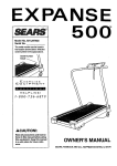
BATTERY INSTALLATION
STEP BY STEP CONSOLE
The console requiresthree "AA" batteries (not included). Alkaline batteries are recommended. Open
the battery cover as shown below. Insertthree batteries intothe battery compartment, making sure that the
negative (-) ends of the batteries are touching the
springs in the battery compartment. Close the battery cover, push up on the battery cover tab, and then
push the tab forward as shown. Be sure that the tab
locks into place.
If there is a thin sheet of clear plastic on the face of the
console, remove it.
OPERATION
Before operating the console, make sure that the
power cord is properlyplugged in. (See HOW TO
PLUG IN THE POWER CORD on page 7.)
Next, step onto the foot rails of the treadmill. Find the
clip attached to the key (see the drawing above), and
slide the clip onto the waistband of your clothing•
Follow the steps on the page 8 to operate the console.
Battery
CoverTab
8
Insertingthe key will
not turn on the displays. The displays will
turn on when the
ON/RESET button is
pressed or when the
walking belt is started.
Note: If you just installed batteries, the displays willalready be on.
CALORIES/FAT CALArrows
ORIES display--This
CALS/_
CALS
display shows the approximate numbers of
calories and fat calories
you have burned. (See
FAT BURNING on
page 14.) Every seven seconds, the display will
change from one number to the other. Arrows in
the display willindicate which number is currently
shown.
Reset the speed control.
To reset the displaysat
any time, press the
/'f_,'_
ON/RESET button.
_
insert the key fully Into the power switch.
©
B
Slide the speed control
down to the RESET
position.Note: Each
time the walking belt
Is stopped, the speed
control must be
moved to the RESET
position before the
walking belt can be
restarted.
u _7.",,t.
]
A..o_
FA_
BU,,
wA.,_
up
_
When you are finished exercising, stop the
_
walking belt and remove the key.
remove the key from the console. The displays will
turn off aboutfive minutesafter the key is removed.
Note: The displays will automatically turn off In
Step
the foot rails,
the walking
beltthat
and
orderonto
to conserve
the stop
batteries
any time
the walking belt Is stopped and the ON/RESET
button Is not pressed for five minutes.
1[_ Start the walking belt.
HOW TO CHANGE THE INCLINE OF THE TREADMILL
After you have moved the speed controlto the
RESET position,slowly slide it upward until the
walking belt begins to move at slow speed.
Carefully step onto the walking belt and begin exercising. Change the speed of the walking belt as
desired by sliding the speed control.
The inclineof the treadmill can be changed by raising
or lowering the back end. Before changing the Incline, remove the key and unplug the power cord.
Hold the
rear roller
endcap
with both
hands.
When the
back end
Hold the Rear
of the
Roller Endca!c
Incline
treadmillis
in these locations
Leg
in the lowest position, the inclineis about 10%. Raise the back end until it
clicks into position. (Note: It may be necessary to shake
the treadmill lightly so that it clicks into position.) The incline will then be about 5%. Raise the back end again
until it clicks into position. The incline will then be about
3%. To lower the back end, raise it past the highest positionand then lower it. CAUTION: Before exercising,
push on the back of the tresdmlll to make sure that
the incline legs are locked In position. Do not place
objects under the treadmill to change the incline;
change the Incline only as described above.
To stop the walking belt, step onto the foot rails
and slide the speed controlto the RESET position.
_
Follow your progress with the three displays.
TIME/DISTANCE
display--This display
shows the elapsed time
L_--/_I.--//and the distance that
you have walked or run
on the treadmill. Every
seven seconds, the display willchange from one
number to the other. A colon (:) will appear when
the elapsed time is shown.
i ITM
°sTANCEI
SPEED display--This
display showsthe
speed of the walking
belt, in miles per hour.
ON/ RES_
l.ffl
SPEED
I
9
HOW TO FOLD AND MOVE THE TREADMILL
HOW TO FOLD THE TREADMILL FOR STORAGE
Before folding the treadmill, unplug the power cord. Caution:
You must be able to safely lift 45 pounds (20 kg) In order
to raise, lower, or move the treadmill.
1. Hold the treadmill with your hands in the locationsshown
at the right. To decrease the possibility of Injury, bend
your legs and keep your back straight. As you raise
the treadmill, make sure to lift with your legs rather
than your back. Raise the treadmill about halfway to the
verticalposition.
2. Move your right hand to the position shownand hold the
treadmillfirmly. Raise the treadmill until the storage latch
closes over the catch. Make sure that the storage latch
Is fully engaged over the catch.
To protect the floor or carpet from damage, place a
mat under the treadmill. Keep the treadmill out of
direct sunlight. Do not leave the treadmill in the storage position in temperatures above 85 ° Fahrenheit.
HOW TO MOVE THE TREADMILL
Before moving the treadmill, convert the treadmillto the storage positionas describedabove. Make sure that the storage latch Is closed fully over the catch.
1. Hold the upper ends of the handrails. Place one foot on
the base as shown.
2. Tilt the treadmill back until it rolls freely on the front
wheels. Carefully move the treadmillto the desired location. Never move the treadmill without tipping It back,
or the base pads may come off. To reduce the risk of
Injury, use extreme caution while moving the treadmill. Do not move the treadmill over an uneven
surface,
3. Place one foot on the base, and carefully lower the treadmill until it is resting in the storage position.
10
ase
_
Front Wheels
HOW TO LOWER THE TREADMILL FOR USE
1. Hold the upper end of the treadmill with your right hand as
shown. Using your left thumb, press the storage latch and
hold it. Pivot the treadmill until the frame and foot rail are
past the storage latch.
2. Hold the treadmill firmly with both hands, and lower the
treadmill to the floor. To decrease the possibility of Injury, bend your legs and keep your back straight,
11
TROUBLE-SHOOTING
Most treadmill problems can be solved by following the simple steps below. Find the symptom that
applies, and follow the steps listed. If further assistance Is needed, call our toll-free HELPLINE st
1-800-736-6879, Monday through Saturday, 7 s.m. until 7 p.m. Central Time (excluding holidays).
1. SYMPTOM: THE POWER DOES NOT TURN ON
a. Make sure that the power cord is plugged into a surge suppressor,and that the surge suppressoris plugged
into a properly groundedoutlet (see page 7). Use only a single-outletsurge suppressorthat is UL 1449
listed as a transient voltage surge suppressor(TVSS). The surge suppressor must have a UL suppressed
voltage rating of 400 volts or less and a minimum surge dissipationof 450 joules. The surge suppressor
must be electricallyrated for 120 volts AC and 15 amps.
b. After the power cord has been plugged in, make sure that the key is fully inserted intothe console. See step
1 on page 9.
c. Check the circuitbreaker located on the treadmill near the
power cord. If the switchprotrudes as shown, the circuit
breaker has tripped. To reset the circuit breaker, wait for five
minutesand then press the switch back in.
Reset
Tripped
Tripped
2. SYMPTOM:
THE POWER TURNS
OFF DURING
Reset
USE
a. Check the circuit breaker located on the treadmill frame near the power cord (see 1. c. above). If the circuit
breaker has tripped, wait for five minutes and then press the switch back in.
b. Make sure that the power cord is plugged in.
c. Remove the key from the console. Reinsert the key fully into the console.See step 1 on page 9.
d. If the treadmill stillwill not run, please call our toll-free HELPLINE.
3. SYMPTOM: THE DISPLAYS OF THE CONSOLE DO NOT FUNCTION PROPERLY
a. Check the batteries in the console. See BATTERY INSTALLATION on page 8. Most problems are the result
of drained batteries.
b. Remove the key from the console and UPLUG THE POWER
CORD. Remove the screwsfrom the hood. Carefully remove the
hood. Locate the Reed Switch (44) and the Magnet (45) on the
left side of the Pulley (50). Turn the Pulley until the Magnet is
aligned with the Reed Switch. Make sure that the gap between
the Magnet and the Reed Switch is about 118". If necessary,
loosen the Screw (89) and move the Reed Switch slightly.
Retighten the Screw. Re-attach the hood, and run the treadmill
for a few minutesto check for a correct speed reading.
12
1/8"
44--
Top
4. SYMPTOM: THE WALKING BELT SLOWS WHEN WALKED ON
a. Use only a UL-listed surge protector, rated at 15 amps, with a 14-gauge cord of five feet or less in length.
b. If the walking belt is overtightened,treadmill performance may
decrease and the walking belt may be permanently damaged.
Remove the key and UNPLUG THE POWER CORD. Using the
allen wrench, turn both rear roller adjustment bolts counterclockwise, 1/4 of a turn. When the walking belt is properly tightened,
you should be able to lift each side of the walking belt 2 to 3
inches off the walking platform. The center of the walking belt
should just touch the walking platform. Be careful to keep the
walking belt centered. Plug in the power cord, insert the key and
run the treadmill for a few minutes. Repeat until the walking belt
is properly tightened.
Rear RollerAdjustment Bolts
c. If the walking belt still slows when walked on, please call our toll-free HELPLINE.
5. SYMPTOM: THE WALKING BELT IS OFF-CENTER WHEN WALKED ON
a. If the walking belt has shifted to the left, first remove the key
and UNPLUG THE POWER CORD. Using the allen wrench,
turn the left rear roller adjustmentbolt clockwise, and the right
bolt counterclockwise,1/4 of a turn each. Be careful not to overtighten the walking belt. Plug in the power cord, insertthe key
and run the treadmillfor a few minutes. Repeat untilthe walking
belt is centered,
b. tf the walking belt has shifted to the right, first remove the
key and UNPLUG THE POWER CORD, Using the allen wrench,
turn the left rear roller adjustmentbolt counterclockwise,and the
right bolt clockwise, 1/4 of a turn each. Be careful not to overtighten the walking belt. Plug in the power cord, insert the key
and run the treadmillfor a few minutes. Repeat untilthe walking
belt is centered.
c. If the walking belt slips when walked on, first remove the key
and UNPLUG THE POWER CORD. Using the allen wrench,
turn both rear rolleradjustment boltsclockwise, 1/4 of a turn.
When the walking belt is correctlytightened, you should be able
to lift each side of the walking belt 2 to 3 inchesoff the walking
platform.Be carefulto keep the walking belt centered. Plug in
the power cord, insertthe key and run the treadmillfor a few
minutes, Repeat untilthe walking belt is properlytightened.
a
b
c
6. SYMPTOM: THE INCLINE SYSTEM STICKS
a. Raise the treadmill to the storage position.See HOW TO FOLD THE TREADMILL FOR STORAGE on page
10. Pivot the incline leg several times to break in the inclinesystem.
13
CONDITIONING GUIDELINES
trainingzone. It may also be helpfulto set the speed
controlon the console to FAT BURN to help you maintain the properintensitylevel. (See page 9.)
Aerobic Exercise
If your goal is to strengthenyour cardiovascularsystem, your exercise must be "aerobic." Aerobic exercise
is activity that requireslarge amountsof oxygen for
prolonged periodsof time. This increasesthe demand
on the heart to pump bloodto the muscles, and on the
lungs to oxygenate the blood. For aerobic exercise,
adjust the speed and inclineof the treadmilluntil your
heart rate is near the highest number in your training
zone. It may also be helpfulto set the speed controlon
the console to AEROBIC to help you maintainthe
proper intensitylevel. (See page 9.)
The followingguidelineswill help you to plan your exercise program. Remember--these are general guidelines only. For more detailed exercise information,obtain a reputablebook or consultyour physician.
EXERCISE INTENSITY
Whether your goal is to burn fat or to strengthenyour
cardiovascularsystem, the key to achievingthe desired resultsis to exercise with the proper intensity.
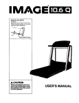
The proper intensitylevel can be found by using your
heart rate as a guide. The chart below shows recommended heart rates for fat burningand aerobic exercise.
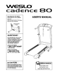
HEART RATE TRAINING
High Performance Athletic Conditioning
If your goal is high performance athletic conditioning,
set the speed control on the console to PERFORMANCE to help you maintain the proper intensity level.
(See page 9.) Note: During the first few weeks of your
exercise program, keep your heart rate near the low
end of your training zone.
ZONE
C
HOW TO MEASURE YOUR HEART RATE
"-l!
( 2O
20
( 30 _._
40
:
50
--::
C60
_--
C7°
80
=_
To measure your
heart rate, stop exercisingand place
two fingers on
your wrist as
shown. Take a sixsecond heartbeat
count, and multiply
the resultby ten to
find your heart
rate. (A six-second count is used because your heart
rate drops quicklywhen you stop exercising.) If your
heart rate is too high or too low, adjust the speed or incline of the treadmillaccordingly.
"i
=-.
,,
,,
To find the proper heart rate for you, first find your age
on the left side of the chart (ages are roundedoff to
the nearest ten years). Next, find the three numbersto
the right of your age. The throe numbers are your
"training zone." The lower two numbers are recommended heart rates for fat burning;the higher number
is the recommended heart rate for aerobic exercise.
WORKOUT GUIDELINES
Fat Burning
A well-rounded workout includes the following three
important pads:
To burn fat effectively,you mustexercise at a relatively
low intensitylevel for a sustained periodof time. During
the first few minutesof exercise, your body uses easily
accessiblecarbohydrate calories for energy. Only after
the first few minutes does your body beginto use
storedfat caloriesfor energy. If your goal is to burn fat,
adjust the speed and inclineof the treadmilluntil your
heart rate is near one of the lowertwo numbers in your
A Warm-up
Start each workout with 5 to 10 minutesof stretching
and light exercise (see SUGGESTED STRETCHES on
page 15). A proper warm-up increases your body
temperature, heart rate, and circulation in preparation
for exercise.
14
Training Zone Exercise
to cool down. This will increase the flexibility of your
muscles and will help to prevent post-axercise problems.
After warming up, increase the intensity of your exercise until your pulse is in your training zone for 20 to
60 minutes. (During the first few weeks of your exercise program, do not keep your pulse in your training
zone for longer than 20 minutes.) Breathe regularly
and deeply as you exercise--never hold your breath.
Exercise Frequency
To maintain or improve yourcondition,complete three
workouts each week, with at least one day of rest between workouts.After a few months, you may complete up to five workouts each week if desired.
A Cool-down
The key to success is to make exercise a regular and
enjoyable part of your everyday life.
Finish each workout with 5 to 10 minutes of stretching
SUGGESTED STRETCHES
The correctform for several basic stretches is shown in the
drawings below. Move slowly as you stretch--never bounce.
1. Toe Touch Stretch
Stand with your knees bent slightlyand slowlybend forward
from your hips. Allow your back and shouldersto relax as you
reach down toward your toes as far as possible. Hold for 15
counts, then relax. Repeat 3 times. Stretches: Hamstrings,
back of knees, and back.
2. Hamstring Stretch
Sit with one leg extended. Bringthe sole of the oppositefoot
toward you and rest it against the inner thigh of your extended
leg. Reach towardyour toes as far as possible. Hold for 15
counts, then relax. Repeat 3 times for each leg. Stretches:
Hamstrings, lower back, and groin.
3. Calf/Achilles Stretch
With one leg in front of the other, reach forward and place your
hands against a wall. Keep your back leg straightand your
back foot flat on the floor. Bend your front leg, lean forward and
move your hipstoward the wall. Hold for 15 counts, then relax.
Repeat 3 times for each leg. To cause further stretchingof the
achillestendons, bend your back leg as well. Stretches:
Calves, achilles tendons, and ankles.
4. Quadriceps Stretch
With one hand against a wall for balance, reach back and
grasp one foot with your other hand. Bring your heel as close
to your buttocks as possible. Hold for 15 counts, then relax.
Repeat 3 times for both legs. Stretches: Quadriceps and hip
muscles.
5. Inner Thigh Stretch
Sit with the soles of your feet together and your knees outward.
Pull your feet toward your groin area as far as possible. Hold
for 15 counts, then relax. Repeat 3 times. Stretches:
Quadriceps and hip muscles.
15
1
2
PART LIST--Model
Key No. Qty.
1
2
3
4
5
6
7
8
9
10"
11
12
13
14
15
16
17
18
19
20*
21
22
23
24
25
26
27
28
29
30
31
32
33
34
35
36
37
38
39
40
41
42
43
44
45
46
47
48
49
2
1
11
1
2
4
1
1
1
1
1
1
8
1
1
2
1
1
1
1
1
6
1
1
10
3
2
2
2
2
2
7
4
4
4
No. 831.297062
Description
Handrail
Key/Clip
Console Screw
Battery Cover
Foot Rail
Foot Rail Cap Screw
Left Rail Cap
Speed Potentiometer
Speed Control Knob
Console Assembly
Upright Base
Motor Belt
Isolator Screw
Storage Latch
4" Cable Tie
8" Cable Tie
Motor Swivel Nut
Pulley/Flywheel/Fan
Motor
MotorlPulleylFlywheellFan
Wire Harness
Hood Screw
Motor Hood
Hood Shield
3/4" Screw
Controller
Motor Swivel Bolt
Motor Tension Nut
Motor Tension Star Washer
Motor Tension Washer
Motor Tension Bolt]InclineLeg Bolt
Right Foot Rail Cap
Adhesive Clip
Extension Leg
Latch Screw
Wheel Bolt
Wheel
Wheel Nut
Adj. Washer/Bumper Washer
Base Pad
Shock
Latch Catch
Reed Switch Clip
Reed Switch
Magnet
Console Base
Frame Pivot Spacer (Left)
PlatformScrew
Isolator
R0399A
Key No. Qty.
50
51
52
53
54
55
56
57
58
59
60
61
62
63
64
65
66
67
68
69
70
71
72
73
74
75
76
77
78
79
80
81
82
83
84
85
86
87
88
89
90
91
92
93
#
#
1
1
2
4
1
1
1
2
2
2
1
2
2
1
1
2
14
1
1
1
1
2
1
1
1
1
2
2
1
2
1
3
1
2
1
1
1
1
1
1
1
8
6
4
1
1
Description
Front Roller/Pulley
Front RollerAdj. Bolt
Incline Wheel
Extension Leg Screw
Power Cord
Power Cord Grommet
Circuit Breaker
Frame Pivot Washer
Frame Pivot Bolt
Roller Guard
Motor Belly Pan
Cable Tie Clamp
Rear PlatformScrew
Releasable Tie
Choke
Belt Guide
Belly Pan Fastener
Walking Belt
Walking Platform
Belly Pan
InclineLeg Bolt
Ratchet Screw
Ratchet SpringScrew
Ratchet
Ratchet Spring
InclineLeg Spacer (long)
InclineLeg Spacer
InclineWheel Bolt
InclineLeg Plate
InclineWheel Nut
Ground Wire
Ground Screw
InclineLeg
Rear RollerAdj. Bolt
Rear Endcap
Latch Decal
Rear Roller
Frame
Allen Wrench
Reed Switch Screw
Frame Pivot Spacer (Right)
Small Screw
Short Belly Pan Screw
IsolatorSpacer
8" White Wire, Male/Female
User's Manual
* Includesall parts shown in the box
# These parts are not illustrated
EXPLODED
DRAWING--Model
No. 831.297062
R0399A
23
53
2
3
89
5
67
68
58
57
69
83
SEARS
The model number and serial number of your PROFORM ®J4
treadmillare listedon a decal attached to the frame. See the front
cover of this manual to find the locationof the decal.
Model No. 831.297062
QUESTIONS?
All replacement parts are available for immediate purchase or
special order when you visit your nearest SEARS Service Center.
To request service or to order parts by telephone, call the toll-free
numbers listed at the left.
If you find that:
• you need help assembling or
operating the PROFORM J4
treadmill
• a part is missing
When requesting help or service, or orderingparts, please be
prepared to providethe followinginformation:
• The NAME OF THE PRODUCT (PROFORIVP J4 treadmill)
• or you need to schedule repair
service
call our toll-free HELPUNE
• The MODEL NUMBER
OF THE PRODUCT
(831.297062)
• The KEY NUMBER AND DESCRIPTION OFTHE PART (see the
EXPLODED DRAWING and PART LIST included in this manual)
1-800-736-6879
Monday-Saturday, 7 am-7 pm
Central Time (excluding holidays)
REPLACEMENT
PARTS
If parts become worn and need
to be replaced, call the following
toll-free number
1-800-FON-PART
(1-800-366-7278)
!
FULL 90 DAY WARRANTY
For 90 days from the date of purchase, if failure occursdue to defect in material or workmanship in this
SEARS TREADMILL EXERCISER, contact the nearest SEARS Service Center throughout the United
States and SEARS will repair or replace the TREADMILL EXERCISER, free of charge.
This warrantydoes not apply when the TREADMILL EXERCISER is used commercially or for rental purposes.
This warranty gives you specific legal rights, and you may also have other rights which vary from state
to state.
SEARS, ROEBUCK AND CO., DEPT. 817WA, HOFFMAN ESTATES, IL 60179
Part No. 152035 H04316AC R0399A
Printed in USA © 1999 Sears, Roebuck and Co.