1
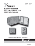
INSTALLATION AND OPERATING
INSTRUCTIONS
Y-200 Series
Electronic Boiler Sequencer & Outdoor
Reset Control System
Catalog No. 5000.62I
Effective: 11-03-10
Replaces: 09-28-09
P/N 241125 Rev. 10
is a registered trademark of Underwriters Laboratories Inc. ®
Rev. 10 reflects the following:
Changes to: Fig. 7 on page 11, Program Mode instructions on page 16, Illustrated Parts List on page 38
Additions: None
Deletions: None
2
CONTENTS
ImPORTANT SAfETY
INSTRUCTIONS
INTRODUCTION
Concept of Operation
Y-200 Controller Configurations
Y-200 Options
INSTALLATION
Mechanical Installation
Electrical Installation
Controller Field Wiring
Communication Field Wiring
Air Temperature Sensor Installation
Water Temperature Sensor Installation
Power Test
Installation Verification Procedure
CONTROLLER
fAmILIARIzATION
Control Screens
Circuit Board Layout
Keypad
Control Screen Displays &
Programming
01 Initial Screen
02 Primary Parameters
03 Control Band
04 Offset
05 Holiday
06 Reset Ratio
07 System Status
08 Water Temperature
09 Outdoor Cut-Off Temperature
10 Outdoor Cut-Off Deadband
11 System Monitor
12 System Temperatures
13 Auxiliary Delay
14 Boiler/Stage On Delay
15 Boiler/Stage Off Delay
16 PID
17 System Temperatures
18 Lead Change Time
19 Password
20 Setup
21 System Test
22 Set Password
23 Water Temperature Limits
24 Master Unit
25 Slave Unit
26 LonWorks
27 Factory Defaults
28 User Defaults
29 Modem Password
30 Alarm Call Telephone
31 Alarm Call ID
32 Alarm Call Retry
33 Alarm Call Events
34 PID
Master Unit with Slaves
Y-200 Master/Slave Diagram
Sensor Resistance
Illustrated Parts List
WARRANTY
4
4
4
5
5
6
6
6
8
9
9
10
11
12
12
13
15
16
17
17
17
18
19
20
20
22
23
23
23
24
24
25
25
26
26
27
27
28
28
29
29
29
3
30
31
31
31
32
32
33
33
33
33
34
34
36
37
38
39
INTRODUCTION
Y–200 SERIES ELECTRONIC
BOILER CONTROL
The Y-200 Series Electronic Boiler Control (controller)
is a microprocessor-based boiler management system
designed to control either single or multiple stage-fired
boilers. Ideally suited for use in hydronic heating and
domestic hot water supply applications, this controller
has been engineered with the flexibility and raw power
to tame the most demanding control situations.
Utilizing state-of-the-art control algorithms, the Y-200
Series minimizes operating costs by maximizing energy efficiency.
SAfETY INSTRUCTIONS
NOTE: These instructions are intended for use by
qualified personnel who are specifically trained and
experienced in the installation of this type of
equipment and related system components.
Installation and service personnel may be required
by some states to be licensed. If your state requires
certification, be sure your contractor bears the
appropriate license. Only qualified persons shall
attempt to repair this equipment. Repair must be
according to these instructions.
Concept of Operation
The controller is an outdoor reset control that is perfect
for managing hydronic heating systems. Two temperature sensors are used to control system response.
One sensor is used to monitor the outdoor temperature, the other sensor is used to regulate the
temperature of the system water. By varying the temperature of the heating medium in response to
changes in the outdoor temperature, the Y-200 Series
provides the ultimate in personal comfort and efficiency of operation.
WARNING: Improper installation, adjustment,
alteration, service or maintenance may damage the
equipment, create a hazard resulting in
asphyxiation, explosion, fire, electric shock, personal
injury or property damage, and will void the warranty.
CAUTION: MORE THAN ONE (1) SUPPLY
SOURCE. THIS APPLIANCE HAS PROVISIONS
TO BE CONNECTED TO MORE THAN ONE (1)
SUPPLY SOURCE. TO REDUCE THE RISK OF
ELECTRIC SHOCK, DISCONNECT ALL SUCH
CONNECTIONS BEFORE SERVICING.
The controller is also well adapted to domestic hot
water supply duty. By disabling the outdoor reset function, the Y-200 behaves as an energy-wise boiler
sequencer. With the ability to control multiple firing
stages, and such features as a revolutionary selectable lead-lag protocol, the Y-200 redefines
"controllability" in domestic water applications.
CAUTION: RISK OF ELECTRIC SHOCK. MORE
THAN ONE (1) DISCONNECT SWITCH MAY BE
REQUIRED TO DE-ENERGIZE THE EQUIPMENT
BEFORE SERVICING.
The controller is equipped with an energy-saving
warm-weather shutdown capability. When the outdoor
temperature rises above an adjustable "Outdoor Cutoff Temperature," the system automatically transitions
to a dormant state. This prevents the system from
wasting energy trying to heat a building that is already
at a comfortable temperature.
Thank you for selecting the Raypak Y–200 Series
Electronic Boiler Control. It is our sincere hope that
you will enjoy its outstanding design, ease of use and
energy-saving features.
Once the outside temperature has fallen to the point
that the system requires heat input to maintain the
building temperature, the Y-200 is reactivated and will
hold the system temperature at the required point.
Please Register
Before proceeding any further, please take a moment
to complete the enclosed user registration form and
mail a copy to: Raypak, Inc., Department Y–200, 2151
Eastman Avenue, Oxnard, CA 93030.
For replacement items, see page 38.
4
Y-200 Controller Configurations
Model No.
Y-241
Y-281
Description
4-Stage Controller - Includes main controller assembly, air temperature sensor assembly (P/N 068634), water temperature assembly (P/N 068635) and
one (1) stage contact board. Main controller includes one (1) mounted auxiliary
contacts board.
8-Stage Controller - Includes main controller assembly, air temperature sensor assembly (P/N 068634), water temperature assembly (P/N 068635) and
two (2) stage contact boards. Main controller includes one (1) mounted auxiliary
contacts board.
Table A: Y-200 Controller Configurations
Y-200 Options
Option No.
Description
Y-300
Alarm Bell, 3” diameter. Shipped loose for field installation.
Y-301
Alarm Bell, 4” diameter. Shipped loose for field installation.
Y-302
Second 4-stage Expansion Board. Converts Y-241 to Y-281. Ships
loose for field installation.
Y-303
Auxiliary Relay Board. Adds control functions for external equipment such as combustion air louvers. Ships loose for field installation.
Y-304
Slave Cable. Connects slave units to the master controller. Ships
loose for field installation.
Y-305
4-20 mA/2-10 VDC Control Board. Accepts 4-20 mA or 2-10 VDC
input from external system such as a BMS to force a specific setpoint.
Ships loose for field installation. Separate instruction manual; see
5000.64.
Y-306
Inlet/Outlet Sensors. Provides a PAIR of sensors for the inlet and
outlet temp. sensing ports. Displays temp. but does not affect control
algorithm.
Y-307
LonWorks Module. Provides full communication between a Y-200
series controller and a LonWorks-enabled system. Cannot have
BOTH this AND a modem. Shipped loose for field installation.
Separate instruction manual; see 5000.63.
Y-308
Modem Module. Provides full communication between a Y-200
series controller and an external system. Cannot have BOTH this
AND a LonWorks. Shipped loose for field installation. Separate
instruction manual; see 5000.65.
Table B: Y-200 Options
5
INSTALLATION
NOTE: Shielded 18 (AWG) stranded gauge wire
must be used to connect the sensors to the
controller. The shielded cable should be protected by
conduit whenever possible.
If the controller was not mounted on the boiler by the
factory, care should be taken to select a suitable
mounting location. The controller should be mounted
on a solid and permanent base. The unit should be
readily accessible for maintenance and installation
purposes, and should be mounted so that the display
is at a height and location convenient for viewing.
NOTE: Minimum 18 AWG, 105°C, stranded wire
must be used for all low voltage (less than 30 volts)
external connections to the unit. Solid conductors
should not be used because they can cause excessive tension on contact points. Install conduit as
appropriate. All high voltage wires must be the same
size (105°C, stranded wire) as the ones on the unit
or larger.
mechanical Installation
Install the controller within 30 feet of the boiler(s). It
must be mounted vertically with the conduit holes facing downward. The conduit holes are sized to
accommodate standard 1/2" conduit fittings. If additional or larger conduit fittings are required, locate the
conduit connections on the bottom of the module.
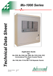
Check Your Power Source
Using a Volt-ohm meter, check the following voltages
at the circuit breaker panel:
Slave units, if present, should be installed adjacent to
the master unit. (Y-304 slave cable is approximately
five feet long.)
Mount the controller using the mounting bracket and
appropriate hardware in four (4) places.
BLACK
CIRCUIT
BREAKER
VOLT-OHM
METER
WHITE
A minimum of eighteen (18) inches clearance from the
front, and six (6) inches clearance on all other sides is
required for service access. The hinged right side of
the box should be installed with sufficient clearance
(minimum 3” from bolt hole on the right side) to open
the cover.
GREEN
GROUND
A B
An electrical distribution sub-panel containing appropriate disconnect switches and surge suppressors is
required at or near the equipment location(s).
C
Fig. 1: Volt-ohm Meter
AC = 108 Volts AC Minimum, 132 Volts MAX
AB = 108 Volts AC Minimum, 132 Volts MAX
BC = Must be less than .6 Volts AC
Electrical Installation
Requires: 120 VAC, Draws 0.5 amp; 60 Hz.
120 VAC Feeder Circuits: Install a surge protection
device sized appropriately for your installation at each
module.
Install a separate disconnect means for each load.
Use appropriately sized wire for equipment as defined
by NEC and/or local code. All primary wiring should be
no less than 125% of minimum rating.
It is strongly recommended that the controller and the
boiler(s) be supplied from the same power source.
Install conduit as appropriate.
6
Controller field Wiring
Power to the Controller
•
•
•
•
•
•
Observe (follow proper) polarity.
Observe proper wire colors while making electrical
connections.
Provide an external surge suppressor capable of
maintaining system integrity.
Provide overload protection and a disconnect
means for equipment serviceability as required by
local and state code.
Conduit cannot be used as the ground. (There
must be a “WIRED” ground.)
Very Important: A grounding electrode conductor shall be used to connect the equipment
grounding conductors, the equipment enclosures,
and where the system is grounded, the grounded
service conductor to the grounding electrode.
for Single-Stage (ON/Off) Boilers
All stage connections on the control board are connected at the {TH} (Thermostat) location on the boiler
wiring diagram.
for multiple-Stage Boilers
First stage connections on the control board are connected at the {TH} (Thermostat) location on the boiler
wiring diagram. Second (or third, etc.) stage connections on the control board are connected at the
locations shown on the boiler wiring diagram.
Fig. 2: Wiring Diagram
7
Notes:
4. For external building control or thermostat control,
remove wiring to J6 (CHF) connector and activate
with 12 to 28 VAC.
1. Tighten terminal strip clamping screws to 2.5 inlbs. Breakage from over-torquing is not covered
under warranty.
2. Use stranded copper conductors only. For supply
connections, use wires sized on the basis of 60°C
(140°F) ampacity and rated a minimum 90°C
(194°F).
3. Install disconnect for each control unit.
Fig. 3: Wiring Diagram
8
Communication (RS485) Wiring
Required for Optional Slave
Unit(s)
Air Temperature Sensor
Installation
Y-304 Slave Cable Installation from
System Control module
•
Y-304 slave cable or equivalent shielded communications cable (Belden #9842, Belden #8132 or
Alpha 3492C) must be used. Maximum cable
length 100 ft. Correct polarity must be observed.
Make use of wire color coding to ensure polarity.
•
The shielding [foil wrapper-bare wire (drain)]
MUST be grounded. Grounding is done at the
Master Y-200 Control only. DO NOT ground the
shield at the slave unit end of the cable.
•
Note: Equivalent shielded cable must be suitable
for RS485 communication applications; must have
100-140 ohm impedance and less than 30 picofarad per foot capacitance.
Fig. 5: Typical Outdoor Air Temperature Sensor
•
Locate the sensor on the coldest side of building,
usually the north side.
•
Must be installed in conduit that does not contain
any other wiring.
•
Install the sensor in a shaded area, out of direct
sunlight.
•
Port J18 (see Fig. 4) is used for the interconnection between the master controller and slave units.
•
Locate no higher than 2/3 way up the side of the
building, or between the 2nd and 3rd floor if the
building is more than 3 stories tall.
•
Master/Slave interconnection should be wired
from Master to Slave #1, Slave #1 to Slave #2,
Slave #2 to Slave #3, and Slave #3 to Slave #4.
•
Do not locate under an overhang, near wall corners, near drafts from stacks, air moving devices,
windows, doors, or balconies.
•
Shielded twisted pair (18 AWG) must be used for
sensor connections. Polarity must be observed.
Cable length shall not exceed 300 feet, and the
shielding must be grounded.
•
Grounding is done at the Master Y-200 control
ONLY. Do Not ground the Slave units or
Temperature Sensor enclosure.
•
Must be installed with properly-sized conduit that
contains no other wiring.
•
The outdoor air temperature and water temperature sensor are identical and interchangeable.
Fig. 4: Master RS485 Communications Cable
Schematic
9
Water Temperature Sensor
Installation
Hydronic Heating Applications
4 OR MORE STAGES OR
4:1 TURN DOWN OR HIGHER
5’ MAX
5’ MAX
12”
MAX
Fig. 6: Typical Water Sensor
•
Hydronic installations may require outdoor reset
function. See page 11 and screen 02.
•
Ensure shielded cable length does not exceed 300
feet. Use 18 AWG shielded wire for sensor connections.
•
Must be installed in properly-sized conduit with no
other wiring.
•
Locate the water sensor as shown in Fig. 6
NOTE: When the system involves a variable-speed
pump, it is recommended that the temperature
sensor be installed in the tee connecting boiler outlet
piping to the system. This is to ensure the control
can respond to the changing conditions of the
system by placing the sensor as close to the blend
location as possible and then provide an appropriate
and measured response to maintain desired system
delivery temperature.
NOTE: Piping diagrams in this manual are not
intended to replace an engineered piping system.
10
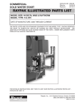
Domestic Hot Water Supply
Applications
Fig. 7: Domestic Hot Water Supply
•
Outdoor reset function should be disabled. See
screen 06 and 24.
Power Test
From
To
TB pin 1
TB pin 2
TB pin 1
Check Power
TB pin 2
Utilizing a Volt-ohm meter (VOM) monitor the following
on the controller for proper voltage levels. Check at the
Terminal Block (TB-1).
Single Point
Ground
Single Point
Ground
Indication
108 VAC to 132
VAC
108 VAC to 132
VAC
Less than 0.6 VAC
Table C: Voltage Measurements
11
CONTROLLER
fAmILIARIzATION
Installation Verification
Procedure
Register
This system is configured utilizing a LCD display (2
lines, 20 characters each) with keypad for data entry.
Open the front cover of the Control Box for access to
the LCD display and keypad. Open the control panel to
gain access to the interface connections.
❏ Before proceeding any further, please verify that
the user registration form has been completed and
mailed.
mechanical Installation
REFER TO THE TABLES ON THE FOLLOWING
PAGES AND THE DISPLAY SCREENS FOR
DETAILED CONFIGURATION INSTRUCTIONS.
❏ Verify that the mechanical installation has been
completed in accordance with the instructions.
NOTE: Controller is shipped with factory defaults.
Your system may require different program settings.
Outdoor Air Temperature Sensor
❏ Verify that all Outdoor Air Temperature Sensor
installation parameters have been met.
Water Temperature Sensor
❏ Verify that the Water Temperature Sensor installation parameters have been met.
Optional Equipment
❏ Verify that optionally ordered equipment installation parameters have been met.
System module Installation
❏ Verify electrical power wiring connections.
❏ Verify electrical connection torque requirements.
❏ Verify Outdoor Air Temperature Sensor wiring.
❏ Verify Water Temperature Sensor wiring.
❏ Verify Power Test has been completed successfully.
12
Control Screens
NOTE: Once programming is finished, go to
Screen 28 to program the USER DEFAULT
SET_UP. Then open the front panel and press
the SW3 reset button on the motherboard to save
the new programming.
To access programming mode: Press and hold the
"MODE" button for 4 seconds. When in Program
mode, cursor is blinking on first settable parameter.
UP/DOWN arrows change parameter. LEFT/RIGHT
arrows move to next selectable parameter.
SCREEN
Initial Screen
DESCRIPTION
01 Displays the product identification and version of software.
Calendar, Time,
The present month, day, year and time in a 24-hour clock
02
Initial Setpoint
format; setpoint temperature.
Temperature can be displayed in degrees Fahrenheit or
Celsius.
°F or °C
02
Setpoint
02 desired when the outdoor temperature is 70°F (21.1°C); or in
40 to 220°F (4.4 to 104.4°C); the system output temperature
domestic hot water applications, the desired water temperature.
FACTORY DEFAULT
None
None
Default Value = °F
Default = 140°F
(60°C)
Control Band
03
1 to 10°F; the temperature above and below the Target
Temperature at which the boiler turns off and on. NOTE: The
Control Band is disabled in PID operation. If the Control Band is
adjusted during PID operation, it disables the PID function.
Offset
04
Degrees of offset added to or subtracted from the initial
setpoint at the date and time selected.
Default = OFF
05 Data from screen 04 is combined with these screen settings.
Default = 00-00-RH
None (for Domestic Hot Water Application ONLY) or 0.01:1 to 8:1;
Default value =
200°F@10°F
(93.3°[email protected]°C)
Setting Holiday
Reset Ratio
06 determines how much the internally-calculated Target
Temperature will change for a given outdoor temperature change.
System Status
Water
Temperature
Limits
07 Shows the status of the system.
08
Maximum "USER" water temperatures 235°F (112.7°C) and
Minimum water temperatures 40°F (4.4°C) Display Only.
32 to 200°F (0 to 93.3°C), a warm-weather shutdown feature.
Outdoor Cutoff
Temperature
09 When the outdoor temperature exceeds this setting, the boiler
Outdoor Cutoff
Deadband
-01 to -10°F; the number of degrees below the Outdoor
10 Cutoff Temperature which causes the Outdoor Cutoff
Temperature to reset.
will not fire unless placed in manual override mode.
System/Network
Displays the Pump, Boiler, Stage and Auxiliary contact
11
Monitor
status. If flashing, contacts are closed (ON).
Outdoor Water
Displays the current Outdoor Air, System Water and Target
12
TAR
Temperature in degrees °F or °C.
AUX Delay
13
000 to 600 seconds; determines when the pump shuts off
after entering Outdoor Cut-off mode.
0 to 600 seconds; sets the time interval between sequential
Boiler/Stage On
14 boiler start-ups. 0 to 600 seconds; sets time interval
Delay
between stages turning on.
Table D: Control Screens
13
Default = 3°F
No value when in PID
None
Max default value =
180°F / 82.2°C
Min default value =
105°F / 40.5°C
Changes: Screen 23
Default value = 75°F
(23.8°C)
Default value = -3°F
This screen is
DISPLAY only.
Default = °F
Default = 180 seconds
Default = 10 seconds
Disabled in PID
SCREEN
DESCRIPTION
0 to 600 seconds; sets the time interval between sequential
Boiler/Stage Off
15 boiler start-ups. 0 to 600 seconds; sets time interval
Delay
between stages turning off.
Selects either Standard or PID operation. If PID is selected
Standard or PID 16
then PID & Interval is programmable using screen 34.
Displays the boiler inlet and outlet temperature in °F or °C
Boiler Inlet/Outlet
17 and the difference (delta) between them. (Requires 4-sensor
Delta(Optional)
installation, option Y-306.)
Auto Lead-Last
18
The lead change time in hours, the lead and last boiler
numbers and the mode (either Auto or Manual).
Password
19
Used to enter a password. This allows access to screens 20
through 34.
Unit Setup/
Network
20
Sets up the pump, boiler and stage configuration for the
System Monitor (Screen 11). Preset = 2 boilers / 4 stages.
System Test
21
Set Password
Water
Temperature
Limits
Master/Slave
Unit
Slaves
Connected
LonWorks
When ACTIVE, initiates auto system test and displays all
screens.
22 Changes the current user password.
23
Sets Maximum and Minimum water temperature limits
allowed by the user in the Water Temperature Screen
24
Displays the number of sensors utilized, relays (stages or
boilers) and Aux contacts.
25 Selects the number of slave units connected, if any.
26 If ON, the LonWorks network will be active.
Factory Defaults 27 If YES selected, the factory defaults will be restored.
User Defaults
Terminal
Password
28
If YES is selected, the User Defaults can be stored or
invoked.
29 Used to enter a password for modem operation.
FACTORY DEFAULT
Default = 10 seconds
Disabled in PID
Default = PID
INLET / OUTLET =
Delta T
Manual:
Default = 100 hours
Default = AAA
To change: Screen 22
Default =
PBSSSBSSSAAA
Note: See Table I
Default = Not Active
Default = AAA
Min. Default = 105°F
(40.5°C), Max. Default =
210°F (98.8°C)
Default = Master
Default = 00
Default = OFF
Default = NO
Default = None
Default = AAA
Alarm Call Tele
30
Modem system telephone number to be called when a fault
occurs.
None
Alarm Call ID
31
Modem system ID person or place to be called when a fault
occurs.
None
Alarm Call Retry 32 Modem system error call retries.
Alarm Call
Events
PID Settings
33 Modem system error indications.
None
None
Default =
Interval = 05
KP = 06
KI = 05
KD = 01
34 Configures PID operation.
Table E: Control Screens (Continued)
manual Override
Internal switches have been provided on each of the stage modules that can be used to manually override the
microcontroller. See switch SW1 on each stage board, page 15.
14
Circuit Board Layout
SW3
Reset Switch
Main Circuit Board
Manual Override Switch
1
Manual Override Switch
4-Stage Relay Board
Auxiliary Board
Fig. 8: Circuit Board Layout
15
Keypad
Normal mode
Move to next screen
Push the "MODE" button to turn off
the alarm horn
Not active except in special modes
Not active except in special modes
Move to previous screen
Program mode
To access programming mode: Press and hold
"MODE" button for 4 seconds. If no button is
pressed while in PROGRAM mode for 30 seconds,
screen returns to normal mode
Increase selected parameter
Move to next programmable
parameter
Move to previous programmable
parameter
Decrease selected parameter
When in PROGRAM mode, cursor is blinking on first
settable parameter. If no button is pressed for 30
seconds, screen returns to NORMAL mode. Press
"MODE" button to store change and return to NORMAL mode
Once programming is finished, press the SW3 reset button on the motherboard to save the new
programming.
16
Control Screen Displays &
Programming
Initial Screen:
Screen number
R
A
Y
P
A
K
Y
-
S
E
R
I
I
E
N
S
C
0
V
Product identification
E
R
X
X
.
X
X
1
X
Version number of software
This is the initial screen displayed after system start-up, provided that there are no faults.
Primary Parameters:
Fahrenheit or Celsius
I
N
I
T
I
A
L
M
M
-
D
D
-
Y
Calendar:
Month-Day-Year
S
Y
E
T
P
O
H
H
M
M
Current time:
24 hour clock
17
I
Screen number
N
T
°
F
0
2
X
X
X
.
X
°
System water temperature desired at
outdoor temperature of 70°F (21.1°C)
Range: 40°F to 220°F(4.4°C to 104.4°C)
Default Value: 140°F (60°C)
Control Band:
C
O
N
T
Screen number
R
O
L
X
X
B
A
N
D
.
X
°
F
0
3
Fahrenheit or Celsius
*C Band is a range of temperature above and below
the target temperature.
Range: 1°F to 10°F (.5°C to 5.5°C)
Default value is 3°F
Control Band (Proportional Only)
The Control Band sets the maximum temperature above and below the Target Temperature (which is determined
by the embedded microcontroller) between which the system temperature may deviate.
This provides a control dead-band that prevents the boiler from short-cycling in proportional mode.
NOTE: The above settings are recommended at
initial installation. For maximum performance and
system efficiency, these settings should be modified
as required to meet such parameters as system
capacity, location and usage.
NOTE: The Control Band is disabled when the unit
is operating in PID mode.
NOTE: PID mode will be disabled if you adjust the
control band.
18
Offset:
Screen number
"OFFSET" screen
O
F
F
S
E
T
O
F
F
0
4
Default "OFF" screen
Press "MODE" to select "OFF" or "ALL" or "FULL WEEK"
Screen number
"ALL" means every day has the same parameters.
O
F
F
—
—
—
S
E
T
A
L
L
X
:
H
H
M
M
+
X
X
.
X
0
4
°
F
Fahrenheit or Celsius
There are six offset adjustments
+, blank or –
allowed for each calendar day. Time in 24-hour
-99 to 99 degrees of offset.
clock mode.
(+) adds to or (-) subtracts from the
initial setpoint (screen 02) to become
active at selected time.
Screen number
"FULL WEEK" screen
O
F
F
X
X
X
S
E
T
F
U
L
L
X
:
H
H
M
M
There are eight days of selectable offsets:
MON
TUE
WED
THU
W
FRI
SAT
SUN
HOL (Holiday)
E
E
K
+
X
X
.
X
0
4
°
F
Fahrenheit or Celsius
+, blank or –
To set an offset, select the day or choose "ALL" for all days. Set the values in degrees. A positive (+) OFFSET
will increase the Water Target Temperature. A negative (-) OFFSET will decrease it. An offset value of 00.0 will
return it to its original value.
-99 to 99 degrees of offset are available.
19
Holiday:
Screen number
S
E
T
T
I
N
H
O
L
#
X
X
G
Thirty two holidays are
selectable (01-32)
H
O
L
I
D
A
Y
X
X
—
X
X
—
X
Month:
01 thru 12
Day:
01 thru 31
0
5
X
Year:
01 to 99; Below 01 is
Repeating Holiday (RH) setting
NOTE: Previous screen (04) is used for entering the
offset value in degrees.
Reset Ratio:
Ratio of outdoor temperature to water system
temperature. Range: . 01:1 to 8:1 or "None" for
constant water temperature
(then TARGET=SETPOINT). Default value is 1.00:1.
R
S
T
X
X
X
.
R
A
T
I
X
@
7
0
O
Default:
System temperature at 70°F (21.1°C)
140°F @ 70°F (60°C @ 21.1°C)
Screen number
X
.
X
X
:
1
X
X
X
.
X
0
@
X
6
X
Default:
System temperature at °F
This value is 200°F @ 10°F (93.3°C @ -12.2°C)
and the second number refers to the degree(s) of
change for the water temperature, e.g., a ratio of 2:1
means for every 2° change in outdoor temperature,
the System Temperature will change 1°. (The reset
temp cannot exceed the temp limits set on screen
#08.)
NOTE: The reset ratio can be modified by changing
either the ratio value in line #1 or the system
temperature value in line #2.
NOTE: When the reset ratio selected is "NONE",
line 2 disappears.
Example: Setpoint = 135°F
NOTE: Use reset ratio "NONE" when using this
controller for domestic hot water or pool applications.
Ratio
The Reset Parameter
2:1
Sets the desired change in system water temperature
increases as the outdoor temperature decreases. The
reset ratio selector is used to determine the rate of
change of the boiler(s) output water temperature relative to a change in the outdoor temperature. The first
number of the ratio refers to the outdoor temperature
Temperature °F
Outdoor
System
70
135
60
140
40
150
20
160
Table F: Outdoor to System Temperature Ratio
20
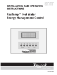
Fig. 10: System to Outdoor Temperature
Typical
Radiation
Reset Ratio Setpoint at Design Temp:
Temp @
Design Cond.
Temp @
70°F
40°F
20°F
0°F
-20°F
Standing
190
105
0.3:1
0.6:1
0.8:1
1.1:1
Convection or
Baseboard
200
105
0.3:1
0.5:1
0.7:1
0.9:1
Fan Coil
Heating
190
105
0.3:1
0.6:1
0.8:1
1.1:1
Fan Coil
Heat and Cool
140
105
0.9:1
1.4:1
2.0:1
2.6:1
Radiant
Floor
120
105
2.0:1
3.3:1
4.7:1
6.0:1
Radiant
Ceiling
120
105
2.0:1
3.3:1
4.7:1
6.0:1
Table G: Suggested Guidelines
21
Advanced Programming
feature
The selection of the correct ratio depends on the initial
temperature Set Point set on screen 02 and the
desired system water temperature. If the building is
too cold, increase the ratio value. After changing the
ratio, wait several days and evaluate the comfort level
before making another change.
Line 2 may be modified by inserting the building
design characteristics into the formula. The Reset
Ratio will be modified to reflect those characteristics.
NOTE: This information works the same in °C (not
shown for clarity).
System Status:
To show the status of other boilers in the system, push either the "LEFT" or "RIGHT" button. If the controller is
in a fault condition, the boiler number can be displayed automatically.
NOTE: The alarm horn can be silenced by pushing
the mode button.
Screen number
S
Y
S
T
E
M
S
T
A
T
U
S
S
Y
S
T
E
M
N
O
R
M
A
L
If more than one ERROR, all errors will be displayed in sequence.
ERROR Indications:
Meaning
Message
NO SAFETY SIGNAL
NO CFH SIGNAL
WATER TEMP>MAX
ILS>OLS
SYS IS OPEN
SYS IS SHORT
OLS IS OPEN
OLS IS SHORT
ILS IS OPEN
ILS IS SHORT
OSS IS OPEN
OSS IS SHORT
Safety signal (24VAC) not present on J7 connector
Call-for-heat signal (24VAC) not present on J6 connector
System water temp > Maximum allowed temp
Inlet water temp > Outlet water temp
System water sensor or cable/connector is open
System water sensor or cable/connector is shorted
Outlet water sensor or cable/connector is open
Outlet water sensor or cable/connector is shorted
Inlet water sensor or cable/connector is open
Inlet water sensor or cable/connector is shorted
Outdoor air sensor or cable/connector is open
Outdoor air sensor or cable/connector is shorted
Table H: Error Indications
22
0
7
Screen number
W
A
T
E
R
M
A
X
:
X
X
T
E
M
X
.
X
P
M
I
N
:
X
X
X
0
8
.
X
Displays the minimum water temperature
for the boiler. Range is determined by
screen number 23. Factory default is
105°F (40.5°C) Minimum.
Displays the maximum water temperature
for the boiler. Range is determined by
screen number 23. Factory default is
180°F (82.2°C) Maximum.
Screen number
O
U
T
D
T
E
M
P
O
O
R
X
C
U
T
O
F
F
X
X
.
X
°
F
0
9
Fahrenheit or Celsius
The outdoor cut-off sets the maximum outdoor temperature at which heat is desired. This control sets the
outdoor temperature above which the boiler bank is disabled. If the outdoor temperature increases beyond the
outdoor cut-off setting, there is no call for heat and the pump turn off delay becomes active. If the outdoor
temperature falls below the outdoor cut-off minus the outdoor cut-off Deadband the boiler bank will again be
enabled.
The Outdoor cut-off Temperature is from 32°F to 200°F (0°C to 93.3°C).
Recommended Initial Setting for outdoor cut-off Temperature is 75°F (23.8°C).
Factory default is 75°F (23.8°C).
Outdoor Cut-Off Deadband:
Screen number
O
U
T
D
O
O
R
D
E
A
D
B
A
N
C
U
T
D
O
F
F
—
X
X
1
.
X
°
0
F
Fahrenheit or Celsius
The Outdoor cut-off deadband sets the number of degrees below the outdoor cut-off where the outdoor cut-off
reset occurs. The outdoor cut-off deadband limit is -1 degree F to -10 degrees F. Default is -3 degrees F.
Note: This parameter can only be set in °F, but will display in °C if °C is chosen.
23
System monitor:
Screen number
S
Y
S
T
E
M
M
A
S
T
E
R
M
O
N
I
T
O
R
P
B
S
S
S
B
S
S
S
A
1
1
A
A
This screen is only a display.
Total # of stages available is set on screen 24.
P=
SYSTEM PUMP MODULE
Rule: Always on before boiler. Always off after last boiler off + programmed delay.
P is relay #1 as supplied.
B=
INDICATES BOILER - 1st Stage
Rule: Always B before S
S=
INDICATES BOILER STAGE - 2nd Stage and Subsequent Stages
Rule: Must have "B" for that boiler ON and prior stages ON for that boiler.
A=
AUXILIARY RELAY MODULE
Optional: A1 - User-defined function. (e.g. powered louvers, boiler pump, draft fan)
A2 - User-defined function. (e.g. alarm light)
A3 - User-defined function. (e.g. alarm bell)
Table I: Definitions
System Pump: "NO SCREEN"
The System Pump Relay works in conjunction with the "OUTDOOR CUT-OFF TEMPERATURE".
System Temperatures:
Screen number
O
U
T
D
O
O
X
X
X
.
X
Current outdoor air
temperature
Displays 000.0
if no sensor is
present
R
W
A
T
E
R
T
A
R
X
X
X
.
X
X
X
X
Current System
Water Temperature
24
1
.
2
X
Target temperature
System design temperature
If system has reached "Outdoor
Cut-off" temp [TAR=O]
Auxiliary Delay:
A
U
X
Screen number
D
E
L
A
Y
X
X
X
1
S
E
3
C
Auxiliary Delay
When CFH signal is "ON" the relay contact of the A1 Auxiliary module stays closed. When the CFH signal
changes to "OFF," the contacts of the relay stay closed as long as the delay is set up.
The AUX contacts operate on a delay after CFH.
AUX turnoff range is 0 to 600 seconds. The default value is 180 seconds.
NOTE: If the "Call-for-Heat" (CFH) or "Safety"
signal is removed from the Y-200, the pump delay
will time out and open the auxiliary contact.
INSTALLERS NOTE: If the end user requires the "System Pump" to be turned off if the "CFH" or "Safety" signal
is removed, it is recommended that the system pump be operated from the "Aux 1 Relay," to provide a delay on
turn off.
Boiler/Stage ON Delay:
NOTE: Refer to screen number 16 (standard)
Screen number
B
O
I
X
X
X
L
R
/
S
S
E
C
T
G
O
N
X
D
X
X
L
Y
S
1
E
4
C
Boiler Turn-On Delay
Stage Turn-On Delay
In a multiple boiler system: The boiler Turn-On Delay
sets the amount of delay before each additional boiler
is turned on in response to a call for heat. This delay
starts when the preceding boiler is turned on.
The Stage Turn-On Delay sets the time delay before a
new stage in a multi-stage boiler configuration is
turned on. This delay starts when the stage or boiler
preceding the next stage is turned on.
The Boiler Turn-On Delay range is from 0 to 600 seconds. Recommended Initial Setting for Boiler Turn-On
Delay is 30 seconds.
The Stage Turn-On Delay range is from 0 to 600 seconds.
Recommended Initial setting stage for Turn-On Delay
is 10 seconds.
Factory default is 30 seconds.
Factory default is 10 seconds.
25
Boiler/Stage Off Delay:
Screen number
B
O
I
X
X
X
L
R
/
S
S
E
C
T
G
O
F
F
X
X
D
X
L
Y
S
E
1
5
C
Boiler Turn-Off Delay
Stage Turn-Off Delay
In a multiple boiler system: The boiler Turn-Off Delay
sets the amount of delay before each additional boiler
is turned off. This delay starts when the preceding boiler is turned off.
The Stage Turn-Off Delay sets the time delay before a
stage in a multi-stage boiler configuration is turned off.
This delay starts when the stage or boiler preceding
the next stage is turned off.
The Boiler Turn-Off Delay range is from 0 to 600 seconds.
The Stage Turn-Off Delay range is from 0 to 600 seconds.
Recommended Initial setting for Boiler Turn-Off Delay
is 30 seconds.
Recommended Initial setting stage for Turn-Off Delay
is 10 seconds.
Factory default is 30 seconds.
Factory default is 10 seconds.
Proportional Integral Derivative (PID):
Screen number
P
I
D
P
=
X
C
X
=
X
X
X
X
D
=
S
X
X
X
=
X
X
I
1
=
X
X
6
X
NOTE: PID mode is the logic control for the microprocessor; disables screens 3, 14 and 15.
Standard:
This is the factory default screen.
Screen number
S
T
A
N
D
A
R
D
1
Standard mode is controlled by:
Screen 3: Control Band
Screen 14: Time On Delay
Screen 15: Time Off Delay
26
6
System Temperatures:
These screen parameters are only available if the inlet and outlet sensors have been installed and selected. See
screen 24.
Screen number
This screen is only a display.
I
N
L
E
T
X
X
X
.
O
X
Current boiler inlet or system
temperature*
U
T
L
E
T
D
E
L
T
A
X
X
X
.
X
X
X
X
.
X
Current boiler outlet or system
temperature*
1
7
Boiler or System delta.*
NOTE: 1. These values are currently reserved for
viewing actual and delta temperatures. 2. If the
sensors are not selected or used, dashes (-) will be
displayed.
Lead Change Time:
Auto or Manual
Screen number
A
U
T
O
1
0
0
—
L
0
If manual lead
change hours
(Displayed in manual)
4
Run time
4
E
A
D
#
X
X
—
Lead boiler
—
L
A
S
T
#
X
X
1
8
Last boiler
for manual Only:
Lead Change Hours
Designated lead boiler will change when remaining hours reaches 0. Range 0-999 hours. Default value is 100
hours. If set at 0 hours lead will not change. Hours remaining will automatically total. Enter the desired number
of hours for the lead boiler operation before change. Hours remaining are automatically calculated.
for Auto Only:
On multiple boiler systems and on each new firing cycle, the lead boiler will change. If a "Last Boiler" is selected, it will always be the last boiler to be called for during a heating cycle.
27
Password:
P
Screen number
A
S
S
W
O
R
D
1
A
A
9
A
Used by maintenance personnel to change settings.
In display mode shows AAA or current password.
To enter the password:
1.Push the mode key. The cursor under the first A should start flashing.
2.Change the first letter by using the up or down key to the desired letter. Use the right key to go to
the next letter and change it with the up or down key. Do the same to the last letter then push the
mode key when done.
• If the password is valid, the screen will allow the user to change to the first setup screen.
Setup:
Screen number
U
N
I
T
M
A
S
T
S
E
E
R
T
—
U
P
P
B
S
B
S
B
S
S
S
A
P=
SYSTEM PUMP MODULE
Rule: Always on before boiler. Always off after last boiler off + programmed delay.
P is relay #1 as supplied.
B=
INDICATES BOILER
Rule: Always B before S
S=
INDICATES BOILER STAGE
Rule: Must have "B" for that boiler ON and prior stages ON for that boiler.
A=
AUXILIARY RELAY MODULE
Optional: A1 - User defined function. (i.e. powered louvers, boiler pump, draft fan)
A2 - User defined function. (i.e. alarm light)
A3 - User defined function. (i.e. alarm bell)
NOTE: Piezo-electric alarm horn can be silenced by pressing the "MODE" switch.
Table J: Definitions
28
2
0
A
A
System Test:
S
Y
S
T
Screen number
E
M
N
O
T
T
E
S
T
A
C
T
2
I
V
1
E
or ACTIVE
This display will cycle between turning all LCD segments on for four (4) seconds then off for four (4) seconds.
To stop this cycling push any button. Self-diagnostics are initiated at 0900 and 1900 hours.
NOTE: 1) When system test is running, this will not
affect control or boiler operation. 2) If system test is
running, it can be terminated by pushing any button.
Set Password:
S
Screen number
E
T
P
A
S
S
W
O
R
A
A
A
D
2
2
In display mode shows AAA or current password.
To change the default password AAA to a new password:
1. Push the mode key. The cursor under the first A should start flashing.
2. Change the first letter by using the up or down key to the desired letter.
3. Use the right key to go to the next letter and change it with the up or down key.
4. Do the same to the last letter then push the mode key when done.
Water Temperature Limits:
W
A
T
E
R
M
A
X
:
X
X
Screen number
T
E
M
X
.
X
P
Maximum programmable setting is 235°F (112.7°C).
Factory default value is 210°F(98.8°C).
L
I
M
I
T
S
M
I
N
:
X
X
X
2
3
.
X
Minimum programmable setting is 40°F (4.4°C).
Factory default value is 105°F (40.5°C).
NOTE: This screen sets the maximum and
minimum values allowable by the user. The values
entered in user screen number 8 cannot exceed the
maximum and minimum values programmed here.
29
master Unit:
Screen number
M
A
S
T
E
S
N
S
:
X
R
2
R
0, 1, 2 or 4
Number of temp. sensors.
E
L
A
Y
:
X
A
1 thru 8
Number of staging contacts in
use. See screen 25.
U
X
:
4
X
0, 1, 2 or 3
Number of auxiliary boards
in use.
If SNS:0
This unit is a slave unit (No sensors required or active)
If SNS:1
Water (System) - Turn outdoor reset ratio to "NONE" on screen 06.
If SNS:2
Water & Outdoor (Activates outdoor reset function on screens 6, 9 and 10.)
If SNS:4
Water, Outdoor, Inlet, Outlet (Activates screen 17.)
This screen limits the programmable parameters available to the user. The information provided is determined
by boiler and control construction.
Stage/Sensor Connections for Y-200 master/Slave Systems
Total no.
of stages
01 - 04
05 - 08
09 - 12
13 - 16
17 - 20
21 - 24
25 - 28
29 - 32
33 - 36
37 - 40
Master unit
Relay
sensors
boards
1
*
1&2
*
1&2
*
1&2
*
1&2
*
1&2
*
1&2
*
1&2
*
1&2
*
1&2
*
Slave 1
Relay
sensors
boards
1
1&2
1&2
1&2
1&2
1&2
1&2
1&2
none
Slave 2
Relay
sensors
boards
1
1&2
1&2
1&2
1&2
1&2
none
Stave 3
Relay
sensors
boards
1
1&2
1&2
1&2
none
* As required for the installation. See above section.
Table K: Connections for Master/Slave Systems
NOTE: The unit with sensors installed is identified
as the master unit.
NOTE: The maximum is 4 sensors and 4 slave
controllers.
30
Slave Unit:
See Staging Table
S
L
A
V
Screen number
E
S
#
C
X
O
N
N
E
C
T
E
D
2
5
X
Number of slaves connected: 01 thru 04
A unit with no sensors attached to it defines itself as the SLAVE unit.
In program mode (see page 32) you identify which SLAVE unit you want it to be.
SLAVE units are numbered from 1 to 4.
Connect the master unit to each slave unit in parallel using RS485 wiring as noted in the Communications
(RS485) Wiring section of this manual.
LonWorks:
Screen number
L
O
N
O
F
F
W
O
R
K
S
2
6
If ON, the LonWorks network is active.
factory Defaults:
Screen number
F
A
C
T
O
R
Y
D
E
N
O
F
A
Press MODE button to get into program mode.
Press UP arrow key to select YES.
Press MODE button to load Factory Defaults and to exit program mode.
NOTE: If unit times out, the factory defaults will not be set.
31
U
L
T
S
2
7
Screen number
F
A
C
T
O
R
Y
D
E
N
O
F
A
U
L
T
S
2
7
Press MODE button to get into program mode.
Press UP arrow key to select YES.
Press MODE button to load Factory Defaults and to exit program mode.
NOTE: If unit times out the factory defaults will not be set.
Screen number
N
U
S
E
O
N
E
R
D
N
E
O
F
A
U
L
T
S
D
E
F
A
U
L
Press MODE button to get into program mode.
S
U
S
E
R
E
T
U
P
D
E
I
S
E
R
N
V
O
K
8
T
Screen number
D
E
F
A
U
L
F
A
U
L
T
S
T
S
Used to store setup parameters.
U
2
2
8
Screen number
E
D
E
D
E
F
A
U
L
F
A
U
L
T
S
T
S
2
8
Press UP or DOWN key to select "Setup Defaults" or "Invoke Defaults". Used to restore setup parameters.
Press MODE button to exit program mode.
T
E
R
M
I
N
A
L
P
Press MODE button to get into program mode.
Enter password
Press MODE button to exit program mode.
32
A
S
S
W
D
X
X
X
X
2
9
Alarm Call Telephone:
A
L
A
R
M
X
X
X
X
X
X
Screen number
C
A
L
L
X
X
X
X
X
T
E
L
E
X
X
X
X
3
0
X
Used to enter telephone number to be called when a fault occurs.
Alarm Call ID:
Screen number
A
L
A
R
M
X
X
X
X
X
X
C
A
L
L
X
X
X
X
I
X
D
3
1
X
Used to identify person or place to be called when a fault occurs.
Alarm Call Retry:
A
L
X
X
A
R
Screen number
M
S
Y
C
A
L
L
R
E
T
R
Y
S
T
E
M
I
D
L
E
.
3
.
2
.
Used to set the number of times (00 to 20) you want the unit to keep calling out when a fault occurs.
Alarm Call Events:
A
L
A
R
M
A
A
A
A
A
Screen number
A
C
A
L
L
A
A
A
A
A
E
V
A
A
Enable or disable system error indications.
Factory default: Enable
Press and hold MODE button to access system error indications.
33
E
N
T
S
X
X
X
X
3
3
X
X
PID
Proportional - Integral - Derivative Control
Interval - time in seconds that the PID updates
KP - Proportional control (01 - 30) - Band in degrees above and below setpoint
KI - Integral control (01 - 99) - Adjustable in % 0.0 - 1.0
KD - Derivative control (01 - 99) - Adjustable in % 0.0 - 10.0
PID Interval:
Screen number
NOTE: Refer to screen number 34 (PID)
P
I
K
P
D
I
X
N
X
T
E
K
I
R
V
A
X
X
L
X
X
K
D
3
X
4
X
Default Values: Interval=05; KP=06; KI=05; KD=01
NOTE: DO NOT change the default values unless
directed to do so in consultation with factory
technical support. Changing of these parameters
may create adverse operating conditions.
master Unit with Slaves
Refer to page 36 for the Master/Slave diagram.
Screen number
Press MODE button to get into program mode.
Go to screen number 25 and select the number of slaves you wish to use, 01 thru 04.
S
L
A
V
E
S
#
C
X
O
N
N
E
C
T
E
D
2
5
X
Screen number
Go to screen number 24 and select the number of sensors, relays and auxiliaries.
M
A
S
T
E
S
N
S
:
X
R
2
R
E
L
A
Y
:
X
A
U
X
E
T
W
O
R
M
A
S
T
E
R
K
S
E
T
-
U
P
P
B
X
X
X
X
34
X
X
Screen number
Go to screen number 20 and set up your Network master and slave operations.
(Setup slave operations prior to Network Set-up on Master Controller.)
N
:
4
X
X
X
2
0
X
X
Screen number
N
E
T
W
O
R
K
S
E
T
S
L
A
V
E
:
1
R
:
X
-
U
P
X
X
X
X
X
X
2
0
X
X
Screen number
N
E
T
W
O
R
K
S
E
T
S
L
A
V
E
:
2
R
:
X
-
U
P
X
X
X
X
X
E
T
X
X
X
X
M
O
N
X
X
X
X
C
B
0
9
X
X
X
X
X
C
5
0
3
X
X
X
X
Slave Unit:
L
A
V
E
S
C
O
N
N
E
C
T
E
A
V
E
S
N
S
:
0
R
E
X
1
1
X
X
2
#
X
X
L
A
Y
2
:
X
A
5
Screen number
NOTE: On slave unit select 0 for number of sensors.
Select which slave number you wish it to be, 01 through 04.
L
X
D
Go to screen number 24 and select the number of sensors, relays and auxiliaries.
S
X
Screen number
Press MODE button to get into program mode.
Go to screen number 25 and display should read.
S
0
Screen number
Go to screen number 11 and it should cycle thru your complete setup.
N
X
2
U
X
:
4
X
Screen number
Go to screen number 20 and set up your unit operations.
U
N
I
T
S
L
A
V
S
E
T
E
-
U
P
P
B
X
Ignore screen number 11 on the slave units.
35
X
X
X
X
X
X
X
2
0
X
X
Y-200 master/Slave Diagram
36
Sensor Resistance at Various
Temperatures
If a sensor error is suspected, perform the following:
1. Examine the wiring, ensuring continuity from controller to sensor(s).
2. Using a multimeter, measure resistance of sensor(s) and compare the value with the Table L
below.
3. If all okay, replace main control board.
Temperature (°F)
Resistance (K Ohms)
-20
1666.3
-10
1193.1
0
863.6
10
631.7
20
466.7
30
348.0
40
262.0
50
199.0
60
153.6
70
119.4
80
93.5
90
73.8
100
58.6
110
46.9
120
37.7
130
30.5
140
24.9
150
20.5
160
16.9
170
14.1
180
11.7
190
9.9
200
8.3
210
7.0
220
6.0
Table L: Sensor Resistance at Various Temperatures
37
Y-200 Illustrated Parts List
Item No.
1-C
2-C
3-C
4-C
5-C
6-C
7-C
8-C
9-C
1-J
1-S
2-S
3-S
4-S
1-M
2-M
10-M
Description
PC Board Assy, Y-200
Expansion Board Assy, 4-Stage
Auxiliary Board Assy
Transformer Assy
LCD Display Assy
Control Keypad
Modem Module
Lon Works Module
4-20 MA/2-10 VDC Module
Wire Bonding Connector
Air Temp Sensor Assy
Water Temp Sensor Assy
Air/Water Temp Sensor
Well Assy
Retainer and Screw
Control Mtg
Ribbon Cable Display
38
Part No.
008846F
008847F
008848F
008705F
012662F
008850F
010792
010791
009823
007155F
008828F
008829F
008845F
004821F
006744F
013435F
011715F
LIMITED WARRANTY
Y-200 Series
SCOPE OF WARRANTY :
Raypak, Inc. ("Raypak") warrants to the original owner the Control System to be free from defects in materials and
workmanship under normal use and service for the applicable warranty period. In accordance with the terms of this Limited
Warranty, RAYPAK will furnish a replacement or repair, at our option, any defective part which fails in normal use and service
during the applicable warranty period. The replacement or repair will be warranted for only the unexpired portion of the original
Warranty Period.
APPLICABLE WARRANTY PERIOD
The effective date of warranty coverage is the date of original installation, of the Control System, by a qualified electrician
or by a RAYPAK authorized service technician. The Applicable Warranty Period is one (1) year from the effective date.
WARRANTY EXCLUSIONS
This Limited Warranty does not apply:
1. if the control system is not properly installed by a qualified technician in accordance with manufacture's installation
instructions, applicable codes, ordinances and good trade practices,
2. to damage or malfunctions resulting from failure to properly install, operate or maintain the system in accordance
with the manufacture's instructions;
3. if the rating plate(s) or serial number(s) are altered, defaced or removed;
4. if the System is modified in any way or used with any non-factory authorized accessories or components;
5. to damage or failure from abuse, accident, act of nature, fire, flood, freezing or the like;
6. to accessories, rubber or plastic parts, light bulbs or glass parts;
7. if the System is moved from its original installation site; or if the original owner no longer owns the site or the System.
LABOR AND SHIPPING COSTS
This Limited Warranty does not cover labor costs for service, removal or reinstallation of any part nor shipping charges
to or from RAYPAK'S designated repair center or to or from the installation site. All such costs are your responsibility.
HOW TO MAKE A WARRANTY CLAIM
To make a warranty claim, promptly ship (postage prepaid) or carry the defective part to a designated RAYPAK Service
Dealer or Service Station in the United States, supplying proof of purchase and date of installation and the model and serial
numbers. If you cannot locate a dealer, contact RAYPAK'S Service Department at the address/telephone listed below.
Raypak reserves the right at all times to inspect the claimed defect and verify warranty coverage at its factory.
EXCLUSIVE WARRANTY - LIMITATION OF LIABILITY
This is the only warranty given by RAYPAK. No one is authorized to make any other warranties on Raypak's behalf. ANY
IMPLIED WARRANTIES, INCLUDING MERCHANTABILITY OR FITNESS FOR A PARTICULAR PURPOSE, SHALL NOT
EXTEND BEYOND THE APPLICABLE WARRANTY PERIOD SPECIFIED ABOVE. RAYPAK'S SOLE LIABILITY WITH
RESPECT TO ANY DEFECT SHALL BE AS SET FORTH IN THIS LIMITED WARRANTY. ANY CLAIMS FOR INCIDENTAL
OR CONSEQUENTIAL DAMAGES (INCLUDING DAMAGE FROM WATER LEAKAGE) ARE EXCLUDED. Some states do
not allow limitations on how long an implied warranty lasts, or for the exclusion of incidental or consequential damages, so
the above limitation or exclusion may not apply to you.
THIS LIMITED WARRANTY GIVES YOU SPECIFIC LEGAL RIGHTS, AND YOU MAY ALSO HAVE OTHER RIGHTS
WHICH VARY FROM STATE TO STATE.
We suggest you immediately complete the information below and retain this Limited Warranty Certificate in case warranty
service is needed.
RAYPAK, INC. SERVICE DEPARTMENT
2151 Eastman Avenue, Oxnard, California 93030
Telephone: (805) 278-5300
FAX (805) 278-5468
The following information must be provided when you write or call:
________________________________________________
Original Owner
_______________________________________________
Daytime Telephone Number
__________________________________________________________________________________________________
Complete Mailing Address
_____________________________________________
City
State
Zip Code
_____________________________________________
Installation Site
_____________________________________________
Model Number
_____________________________________________
Contractor/Installer
______________________________________________
Date of Installation
_____________________________________________
Serial Number
39
Raypak, Inc., 2151 Eastman Avenue, Oxnard, CA 93030 (805) 278-5300 Fax (805) 278-5495
Litho in U.S.A.