1
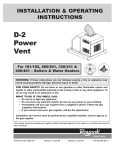
Hi Delta SS™, TYPE H - MODELS HD101-HD401
SUGGESTED SPECIFICATIONS
Catalog No.:
Effective:
Replaces:
2000.961
6-25-09
New
DIVISION 23 52 33.13
FINNED WATER-TUBE BOILERS
PART 1 - GENERAL
1.1
SUMMARY
A. Section includes gas-fired, copper finned-tube hydronic heating boilers
B. Related Sections
Specifier Note: Use as needed
1. Building Services Piping – Division 23 21 00
2. Breeching, Chimneys, and Stacks (Venting) – Division 23 51 00
3. HVAC Instrumentation and Controls – Division 23 09 00
4. Electrical – Division 23 09 33
1.2
REFERENCES
A. ANSI Z21.13/CSA 4.9
B. ASME, Section IV
C. 2006 UMC, Section 1107.6
D. ANSI/ASHRAE 15-1994, Section 8.13.6
E. National Fuel Gas Code, ANSI Z223.1/NFPA 54
F. I=B=R
G. NEC
1.3
SUBMITTALS
A. Product data sheet (including dimensions, rated capacities, shipping weights, accessories)
B. Wiring diagram
C. Warranty information
D. Installation and operating instructions
1.4
QUALITY ASSURANCE
A. Regulatory Requirements
1. ANSI Z21.13/CSA 4.9
2. Local and national air quality regulations for low NOx (<20 PPM NOx emissions) boilers
B. Certifications
1. CSA
2. ASME H Stamp and National Board Listed
3. ISO 9001
1.5
WARRANTY
A. Limited one-year warranty from date of installation
B. Limited twenty-year thermal shock warranty
C. Limited ten-year closed-system heat exchanger warranty
PART 2 - PRODUCTS
2.1
MANUFACTURER
A. Raypak, Inc.
1. Contact: 2151 Eastman Ave., Oxnard, CA 93030; Telephone: (805) 278-5300;
Fax: (800) 872-9725; Web site: www.raypak.com
Project Name / Date
Division 23 52 33.13 - 1
2. Product: Hi Delta SS™ copper finned-tube hydronic boiler(s)
2.2
BOILERS
A. General
1. The boiler(s) shall be fired with
gas at a rated input of
BTU/hr.
2. The boiler(s) shall be CSA tested and certified with a minimum thermal efficiency of 84 percent
at full fire.
3. The boiler(s) shall be ASME inspected and stamped and National Board registered for 160
PSIG working pressure, complete with a Manufacturer's Data Report.
4. The boiler(s) shall have a floor loading of 45 lbs. /square foot or less.
B. Heat Exchanger
1. The heat exchanger shall be of a single-bank, horizontal-grid design with nine integral copper
fin tubes, each end of which is rolled into an ASME boiler-quality steel tube sheet.
2. The heat exchanger shall be sealed to 160 PSIG rated cast iron headers with high
temperature silicone "O" ring gaskets.
3. The low water volume heat exchanger shall be explosion-proof on the water side and shall
carry a twenty-year warranty against thermal shock.
4. The headers shall be secured to the tube sheet by stud bolts with flange nuts to permit
inspection and maintenance without removal of external piping connections.
5. The boiler(s) shall be capable of operating at inlet water temperatures as low as 105°F without
condensation.
C. Burners
1. The tubular burners shall have gas orifices, punched ports and slots, be capable of quiet
ignition and extinction without flashback at the orifice, and be manufactured from corrosionresistant, stainless steel with low expansion coefficient.
2. The burners will be supplied with a fan-assisted, clean burning, and highly efficient fuel-air
mixture.
D. Pilot Control System
1. The boiler(s) shall be equipped with a 100 percent safety shutdown system.
2. The ignition shall be Hot Surface Ignition type with full flame rectification by remote sensing
separate from the ignition source, with a three try-for-ignition sequence, to ensure consistent
operation.
3. The igniter will be located away from the water inlet to protect the device from condensation
during startup.
4. An external viewing port shall be provided, permitting visual observation of burner operation.
E. Gas Train
1. The boiler(s) shall have dual-seated main gas valve(s).
2. Gas control trains shall have a redundant safety shut-off feature, main gas regulator, and
plugged pressure tapping to meet the requirements of ANSI Z21.13/CSA 4.9.
F. Boiler Control
1. The following safety controls shall be provided:
a. High limit control
b. Flow switch
c.
PSIG ASME pressure relief valve, piped by the installer to an approved drain
d. Temperature and pressure gauge
2. The boiler(s) shall be equipped with an energy-saving pump control relay (Economaster),
mounted and wired, which automatically shuts off the boiler pump at a set period after boiler
shut-down (adjustable for two settings of five or ten minutes) to avoid standby losses
associated with constant pump operation.
G. Firing Mode
1. For models HD101 – HD401, provide two-stage fire control of the gas input to the boiler (on/off
fire optional).
H. Boiler Diagnostics
Project Name / Date
Division 23 52 33.13 - 2
1. Provide internal LED displaying the following boiler status/faults:
a. Steady on – Internal control failure
b. One flash – Air flow fault
c. Two flashes – Erroneous flame signal
d. Three flashes – Ignition lockout
I.
Combustion Chamber: The lightweight, high-temperature, multi-piece, interlocking ceramic fiber
combustion chamber liner shall be sealed to reduce standby radiation losses, reducing jacket
losses and increasing unit efficiency.
J.
Venting
1. When routed vertically, the boiler’s flue material and size shall be in accordance with the
National Fuel Gas Code, ANSI Z223.1/NFPA54 latest edition (Category I).
2. When routed horizontally, the boiler(s) flue material and size shall meet or exceed the
requirements as specified for Category III in the National Fuel Gas Code, ANSI Z223.1/NFPA
54 latest edition.
3. The boiler(s) shall be TruSeal™ direct vent ready. The boiler(s) shall meet safety standards
for direct vent equipment as noted by: the 2006 UMC Section 1107.6; ASHRAE 15-1994,
Section 8.13.6; and ANSI Z21.13/CSA 4.9.
K. Cabinet
1. The corrosion-resistant galvanized steel jackets shall be finished with a baked-on epoxy
powder coat which is suitable for outdoor installation, applied prior to assembly for complete
coverage, and shall incorporate louvers in the outer panels to divert air past heated surfaces.
2. The boiler(s), if located on a combustible floor, shall not require a separate combustible floor
base.
3. Combustion air intake shall be on the left side of the cabinet.
L. Operating Controls
1. The boiler(s) shall feature an optional controller.
Specifier Note: The remaining items in this section are options. Delete those that are not being
specified.
M. Boiler Pump - Refer to Equipment Schedule
N. Cold Water Run System
1. The boiler(s) shall be configured with a cold water run automatic proportional bypass system
that ensures the boiler will experience inlet temperatures in excess of 105ºF in less than 7
minutes to avoid damaging condensation. The unit will automatically shut down if the inlet
temperature is not achieved within the 7 minute time frame.
2. The cold water run system shall be configured with a variable speed pump that is controlled by
a system-matched PID control that injects the correct amount of cold water directly into the
boiler loop to maintain a minimum inlet temperature. The PID controller temperature sensor
shall be located in the inlet header of the boiler.
3. The control shall have a temperature setting dial located on the face of the board. The
temperature range of the dial shall be 105ºF to 120ºF. The PID Logic shall be capable of
limiting system overshoot to a maximum of 10ºF on initial start-up or call-for-heat.
4. The cold water run system shall be shipped loose for field installation.
5. The cold water run pump shall have the following diagnostic LED’s:
a. Power
b. Heat Request
c. Reduced Out
d. % Out
2.3
SOURCE QUALITY CONTROL
A. The boiler(s) shall be completely assembled, wired, and fire-tested prior to shipment from the
factory.
B. The boiler(s) shall be furnished with the sales order, ASME Manufacturer’s Data Report,
inspection sheet, wiring diagram, rating plate and Installation and Operating Manual.
Project Name / Date
Division 23 52 33.13 - 3
PART 3 - EXECUTION
3.1
INSTALLATION
A. Must comply with:
1. Local, state, provincial, and national codes, laws, regulations and ordinances
2. National Fuel Gas Code, ANSI Z223.1/NFPA 54 – latest edition
3. National Electrical Code, ANSI/NFPA 70 – latest edition
4. Canada only: CAN/CSA B149 Installation Code and CSA C22.1 CEC Part I
5. Manufacturer’s installation instructions, including required service clearances and venting
guidelines
B. Manufacturer’s representative to verify proper and complete installation.
3.2
START-UP
A. Shall be performed by Raypak factory-trained personnel.
B. Test during operation and adjust if necessary:
1. Safeties
2. Operating Controls
3. Static and full load gas supply pressures
4. Gas manifold and blower air pressures
C. Submit copy of start-up report to Architect and Engineer.
3.3
TRAINING
A. Provide factory-authorized service representative to train maintenance personnel on procedures
and schedules related to start-up, shut-down, trouble shooting, servicing, and preventive
maintenance.
B. Schedule training at least seven days in advance.
END OF SECTION
Project Name / Date
Division 23 52 33.13 - 4