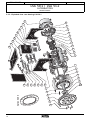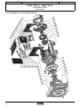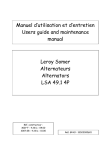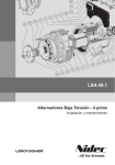
1
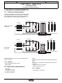
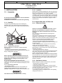
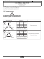
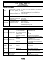
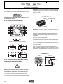
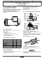
Réf. 3281 en - 10.2007 / g
n to
e
v
i
be g
o
t
s
ua l i
n
ser
a
u
m
d
n
s
Th i
the e
49
48
193
190
205
198
203
50
41
4
P5
P4
P3
LSA 50.1 / LSA 51.2
ALTERNATORS
Installation and maintenance
LEROY-SOMER
INSTALLATION AND MAINTENANCE
Réf. 3281 en - 10.2007 / g
LSA 50.1 / LSA 51.2
ALTERNATORS
This manual concerns the alternator which
you have just purchased.
The latest addition to a whole new generation
of alternators, this range benefits from the
experience of the leading manufacturer
worldwide, using advanced technology and
incorporating strict quality control.
We wish to draw your attention to the contents
of this maintenance manual. By following
certain important points during installation,
use and servicing of your alternator, you can
look forward to many years of trouble-free
operation.
WARNING SYMBOLS
SAFETY MEASURES
Before using your machine for the first time, it is important to
read the whole of this installation and maintenance manual.
A set of self-adhesive stickers depicting the various warning
symbols is included with this maintenance manual. They
should be positioned as shown in the drawing below once the
machine has been fully installed.
All necessary operations and interventions on this machine
must be performed by a qualified technician.
Our technical support service will be pleased to provide any
additional information you may require.
The various operations described in this manual are
accompanied by recommendations or symbols to alert the
user to potential risks of accidents. It is vital that you
understand and take notice of the following warning symbols.
WARNING
Warning symbol for an operation capable of damaging or
destroying the machine or surrounding equipment.
Warning symbol for general danger to personnel.
Warning symbol for electrical danger to personnel.
Note : LEROY-SOMER reserves the right to modify the
characteristics of its products at any time in order to
incorporate the latest technological developments. The
information contained in this document may therefore be
changed without notice.
2
Copyright 2001 : MOTEURS LEROY-SOMER
This document is the property of :
MOTEURS LEROY-SOMER
It may not be reproduced in any form without prior
authorization.
All brands and models have been registered and patents
applied for.
LEROY-SOMER
INSTALLATION AND MAINTENANCE
Réf. 3281 en - 10.2007 / g
LSA 50.1 / LSA 51.2
ALTERNATORS
CONTENTS
1 - RECEIPT .............................................................. 4
Standards and safety measures
Inspection
Identification
Storage
2 - TECHNICAL CHARACTERISTICS ..................... 5
Electrical characteristics
Options
Mechanical characteristics
Options
3 - INSTALLATION .................................................. 6
Assembly
Handling
Coupling
Location
Inspection prior to first use
Electrical checks
Mechanical checks
Terminal connection diagrams
Terminal connection
Connection checks
Electrical checks on the AVR
Commissioning
Settings
R 449 settings
Max. excitation setting
Special type of use
4 - SERVICING - MAINTENANCE ......................... 8
Safety measures
Regular maintenance
Checks after start-up
Cooling circuit
Bearings
Electrical servicing
Mechanical servicing
Fault detection
Mechanical defects
Electrical faults
Checking the winding
Checking the diode bridge
Checking the windings and rotating diodes
using separate excitation
Dismantling, reassembly
Tools required
Screw tightening torque
Access to diodes
Access to connections and the regulation system
Replacing the NDE bearing on
single-bearing machines
Replacing the DE bearing on
two-bearing machines
Complete dismantling
Reassembling the bearings
Reassembling the rotor
Installation and maintenance of the PMG
Mechanical characteristics and assembly
Electrical connection
Table of electrical characteristics
5 - SPARE PARTS ................................................... 14
First maintenance parts
Technical support service
Exploded views, parts list
Parts list
Exploded view : single-bearing
Exploded view : two-bearing
DE bearing assembly
NDE bearing assembly
PMG assembly
3
LEROY-SOMER
INSTALLATION AND MAINTENANCE
Réf. 3281 en - 10.2007 / g
LSA 50.1 / LSA 51.2
ALTERNATORS
RECEIPT
1 - RECEIPT
.
1.1 - Standards and safety measures
Our alternators comply with most international standards and
are compatible with :
- the recommendations of the
International Electrotechnical Commission
IEC 34-1, (EN 60034).
- the recommendations of the
International Standards Organisation ISO 8528.
- the European Community directive 89/336/EEC on
Electromagnetic Compatibility (EMC).
- the European Community directives 73/23/EEC and
93/68/EEC (Low Voltage Directive).
They are CE marked with regard to the LVD (Low Voltage
Directive) in their role as a machine component. A declaration
of incorporation can be supplied on request.
Before using your generator for the first time, read carefully
the contents of this installation and maintenance manual,
supplied with the machine. All operations performed on the
generator should be undertaken by qualified personnel with
specialist training in the commissioning, servicing and
maintenance of electrical and mechanical machinery. This
maintenance manual should be retained for the whole of the
machine’s life and be handed over with the contractual file.
The various operations described in this manual are
accompanied by recommendations or symbols to alert the
user to potential risks of accidents. It is vital that you
understand and take notice of the different warning symbols.
1.2 - Inspection
On receipt of your alternator, check that it has not suffered
any damage in transit. If there are obvious signs of knocks,
contact the transporter (you may able to claim on their
insurance) and after a visual check, turn the machine by hand
to detect any malfunction.
1.3 - Identification
The alternator is identified by means of a nameplate fixed on
the frame.
Make sure that the nameplate on the machine conforms to
your order.
The machine name is defined according to various criteria
(see below).
Example of description for : LSA 50.1 M6/4 • LSA : name used in the PARTNER range
M : Marine / C : Cogeneration / T : Telecommunications
• 50.1 : machine type
• M6 : model
• 4 : number of poles
1.3.1 - Nameplate
So that you can identify your machine quickly and accurately,
we suggest you fill in its specifications on the nameplate
4
1.4 - Storage
Prior to commissioning, machines should be stored :
- Away from humidity : in conditions of relative humidity of
more than 90%, the machine insulation can drop very rapidly,
to just above zero at around 100%; monitor the state of the
anti-rust protection on unpainted parts.
For storage over an extended period, the machine can be
placed in a sealed enclosure (heatshrunk plastic for example)
with dehydrating sachets inside, away from significant and
frequent variations in temperature to avoid the risk of
condensation during storage.
- If the area is affected by vibration, try to reduce the effect of
these vibrations by placing the generator on a damper
support (rubber disc or similar) and turn the rotor a fraction of
a turn once a fortnight to avoid marking the bearing rings.
WARNING
This manual is applicable to the LSA 50.1 alternator
manufactured at Sillac commencing from serial number : 132000
This manual is applicable to the LSA 51.2 alternator
manufactured at Orléans commencing from serial number :
168500.
LEROY-SOMER
INSTALLATION AND MAINTENANCE
Réf. 3281 en - 10.2007 / g
LSA 50.1 / LSA 51.2
ALTERNATORS
TECHNICAL CHARACTERISTICS
2 - TECHNICAL CHARACTERISTICS
2.1 - Electrical characteristics
LSA 50.1 / 51.2 alternators are machines without sliprings or
revolving field brushes, wound as "2/3 pitch", 6-wire, with
class H insulation and a field excitation system available in
either AREP+PMI or "PMG" version (see diagrams).
STATOR
MAIN FIELD
Aux. windings
Surge suppressor
EXCITER
Armature
AREP+PMI system
with R 449
5+
Field
6-
T1
T2
T3
T4
T5
T6
R 449
MAIN FIELD
Armature
5+
Field
STATOR
Surge suppressor
EXCITER
PMG system
with R 449
6-
Interference suppression conforms to standard EN 55011,
group 1, class B.
2.1.1 - Options
- Stator temperature detection probes
- Space heaters
2.2 - Mechanical characteristics
Steel frame
End shields in cast iron
Greasable ball bearings
Mounting arrangement
T1
T2
T3
T4
T5
T6
PMG
R 449
-
Voltage detection
Voltage detection
MD 35 :
single bearing with standard feet and SAE flanges/coupling
discs.
B 34 :
two-bearing with SAE flange and standard cylindrical shaft
extension.
- Drip-proof machine, self-cooled
- Degree of protection : IP 23
2.2.1 - Options
- Air inlet filter, air outlet filter
5
LEROY-SOMER
INSTALLATION AND MAINTENANCE
Réf. 3281 en - 10.2007 / g
LSA 50.1 / LSA 51.2
ALTERNATORS
INSTALLATION
3 - INSTALLATION
3.1.3 - Location
3.1 - Assembly
Ensure that the ambient temperature in the room where the
alternator is placed cannot exceed 40°C for standard power
ratings (for temperatures > 40°C, apply a derating
coefficient). Fresh air, free from damp and dust, must be able
to circulate freely around the air intake grille on the opposite
side from the coupling. It is essential to prevent not only the
recycling of hot air from the machine or engine, but also
exhaust fumes.
All mechanical handling operations must be undertaken
using approved equipment.
The machine should remain horizontal during handling.
3.2 - Inspection prior to first use
3.1.1 - Handling
The generously-sized lifting rings are for handling the
alternator alone. They must not be used to lift the genset.
Choose a lifting system which respects the positioning of the
rings.
3.1.2 - Coupling
3.1.2.1 - single bearing alternator
Before coupling the two machines, check that both are
compatible by :
- undertaking a torsional analysis of the transmission
- checking the dimensions of the flywheel and its housing, the
flange, coupling discs and offset
WARNING
When coupling the alternator to the prime mover, the
holes of the coupling discs should be aligned with the
flywheel holes by rotating the primary pulley on the
thermal engine.
Do not use the alternator fan to turn the rotor.
Tighten the coupling disc screws to the recommended torque
(see section 4.6.2.) and check that there is lateral play on the
crankshaft.
3.1.2.2 - two-bearing alternator
- Semi-flexible coupling
Careful alignment of the machines is recommended, by
checking that any differences in the concentricity and
parallelism of both parts of the coupling does not exceed 0.1 mm.
WARNING
This alternator has been balanced with a 1/2 key.
6
3.2.1 - Electrical checks
Under no circumstances should an alternator, new or
otherwise, be operated if the isolation is less than 1
megohm for the stator and 100,000 ohms for the other
windings.
There are three possible methods for restoring these
minimum values.
a) Dry out the machine for 24 hours in a drying oven at a
temperature of approximately 110 °C (without the AVR)
b) Blow hot air into the air intake, having made sure that the
machine is rotating with the exciter field disconnected.
c) Run in short-circuit mode (disconnect the AVR) :
- Short-circuit the three output power terminals using
connections capable of supporting the rated current (try not to
exceed 6 A/mm2).
- Insert a clamp ammeter to monitor the current passing
through the short-circuit connections.
- Connect a 24 Volt battery in series with a rheostat of
approximately 10 ohms (50 W) to the exciter field terminals,
respecting the polarity.
- Open fully all the alternator openings.
- Run the alternator at its rated speed, and adjust the exciter
field current using the rheostat to obtain the rated output
current in the short-circuit connections.
Note : Prolonged standstill : In order to avoid these problems,
we recommend the use of space heaters, as well as turning
over the machine from time to time. Space heaters are only
really effective if they are working continuously while the
machine is stopped.
3.2.2 - Mechanical checks
Before starting the machine for the first time, check that :
- all fixing bolts and screws are tight
- cooling air is drawn in freely
- the protective grilles and housing are correctly in place
- the standard direction of rotation is clockwise as seen from
the shaft end (phase rotation in order 1 - 2 - 3).
For anti-clockwise rotation, swap 2 and 3.
- the winding connection corresponds to the site operating
voltage (see section 3.3)
LEROY-SOMER
INSTALLATION AND MAINTENANCE
Réf. 3281 en - 10.2007 / g
LSA 50.1 / LSA 51.2
ALTERNATORS
INSTALLATION
3.3 - Terminal connection diagrams
To modify the connections, change the position of the
terminal cables. The winding code is specified on the
nameplate.
3.3.1 - Terminal connection
Any intervention on the alternator terminals during
reconnection or checks should be performed with
the machine stopped.
Connection code
Voltage L-L
Ph1-L1
D
T1-U1
Winding
50 Hz
60Hz
Star
3 PH
T6-W2
T3-W1
8S
T2-V1
347
AVR connector
Factory connection
380 - 416
0 - 380 V
Ph1-L1
C
Bobinage
T6 -W2
T1-U1
6S
3 PH
T3-W1
T5-V2
Ph3-L3
380 - 415 380 - 480
Ph2-L2
Ph3-L3
Delta
6S
T4-U2
T5-V2
T4-U2
T2-V1
8S
50 Hz
60Hz
220 - 240 220 - 255
200
AVR connector
220 - 240
Connection using optional kit
Consult the factory
0 - 220 V
Ph2-L2
7
LEROY-SOMER
INSTALLATION AND MAINTENANCE
Réf. 3281 en - 10.2007 / g
LSA 50.1 / LSA 51.2
ALTERNATORS
SERVICING - MAINTENANCE
4 - SERVICING - MAINTENANCE
4.1 - Safety measures
temperature. Should this value be exceeded, the machine
must be stopped and checks carried out.
4.2.4 - Electrical servicing
Cleaning product for the windings
WARNING
Servicing or troubleshooting must be carried out strictly
in accordance with instructions so as to avoid the risk of
accidents and to maintain the machine in its original
state.
All such operations performed on the alternator should
be undertaken by personnel trained in the
commissioning, servicing and maintenance of electrical
and mechanical components.
Before any intervention on the machine, ensure that it cannot
be started by a manual or automatic system and that you
have understood the operating principles of the system.
4.2 - Regular maintenance
4.2.1 - Checks after start-up
After approximately 20 hours of operation, check that all fixing
screws on the machine are still tight, plus the general state of
the machine and the various electrical connections in the
installation.
DO NOT USE : TRICHLORETHYLENE,
PERCHLORETHYLENE, TRICHLOROETHANE OR ANY
ALKALINE PRODUCTS.
Certain strictly defined pure volatile degreasing products can
be used, such as :
- Normal petrol (without additives)
- Toluene (slightly toxic); inflammable
- Benzene (or benzine, toxic); inflammable
- Ciclohexare (non toxic); inflammable
Cleaning of the stator, rotor, exciter and diode bridge
The insulating components and the impregnation system are
not at risk of damage from solvents (see the list of authorised
products).
Avoid letting the cleaning product run into the slots. Apply the
product with a brush, sponging frequently to avoid
accumulation in the housing. Dry the winding with a dry cloth.
Let any traces evaporate before reassembling the machine.
4.2.5 - Mechanical servicing
WARNING
4.2.2 - Cooling circuit
It is advisable to check that circulation of air is not reduced by
partial blocking of the air intake and outlet grilles : mud, fibre,
grease, etc.
4.2.3 - Bearings
The bearings are greasable. It is advisable to lubricate the
machine during operation. Time intervals and quantity of
grease are given in the table below.
Bearing
6226 C3
6232 C3
Quantity of grease
50 g
70 g
Lubrication interval
3600 H
1700 H
Bearing
Quantity of grease
NU 1028 MC3
35 g
Lubrication interval
2000 H
Lubrication intervals are given for a grease of grade
LITHIUM - standard - NLGI 3.
The factory lubrication is performed with grease :
ESSO UNIREX N3 (LSA 50.1)
SHELL RETINAX LX (LSA 51.2).
Before using another grease, check for compatibility with the
original one. Monitor the temperature rise in the bearings,
which should not exceed 50°C above the ambient
8
Cleaning the machine using water or a high-pressure
washer is strictly prohibited.
Any problems arising from such treatment are not
covered by our warranty.
Degreasing : Use a brush and detergent (suitable for
paintwork).
Dusting : Use an air gun.
If the machine is fitted with air filters, these should be cleaned
regularly according to the environmental conditions.
After cleaning the alternator, it is essential to check the
winding insulation (see sections 3.2. and 4.8.).
4.3 - Fault detection
If, when commissioned, the alternator does not work
normally, the source of the malfunction must be identified.
To do this, check that :
- the protective devices are fitted correctly
- the connections comply with diagrams in the manuals
supplied with the machine
- the speed of the unit is correct (see section 1.3).
Repeat the operations defined in section 3.
LEROY-SOMER
INSTALLATION AND MAINTENANCE
Réf. 3281 en - 10.2007 / g
LSA 50.1 / LSA 51.2
ALTERNATORS
SERVICING - MAINTENANCE
4.4 - Mechanical defects
Fault
Bearing
Abnormal
temperature
Cause
Excessive overheating of one or both
bearings (bearing temperature 50°C
above the ambient temperature) (With or
without abnormal bearing noise)
- Air flow (inlet-outlet) partially clogged or hot air is being recycled from
Excessive overheating of alternator frame the alternator or engine
- Alternator operating at too high a voltage (> 105% of Un on load)
(more than 40° C above the ambient
- Alternator overloaded
temperature)
Too much vibration
- Misalignment (coupling)
- Defective mounting or play in coupling
- Rotor balancing fault (Engine - Alternator)
Excessive vibration and humming noise
coming from the machine
- Phase imbalance
- Stator short-circuit
Vibrations
Abnormal noise
- If the bearing has turned blue or if the grease has turned black, change the
bearing.
- Bearing not fully locked (abnormal play in the bearing cage)
- End shields incorrectly aligned
Alternator damaged by a significant
impact, followed by humming and
vibration
- System short-circuit
- Misparalleling
Possible consequences
- Broken or damaged coupling
- Broken or bent shaft end
- Shifting and short-circuit of main field
- Fan fractured or coming loose on shaft
- Irreparable damage to rotating diodes/AVR
4.5 - Electrical faults
Fault
Action
Effect
Check/Cause
The alternator builds up and its voltage
is still correct when the battery is
- Lack of residual magnetism
removed.
No voltage at no Connect a new battery of 4 The alternator builds up but its voltage
load on start-up to 12 volts to terminals E- does not reach the rated value when
and E+, respecting the
the battery is removed.
polarity, for 2 to 3 seconds
- Check the connection of the voltage reference to the
AVR
- Faulty diode
- Armature short-circuit
The alternator builds up but its voltage
disappears when the battery is
removed.
- Faulty AVR
- Field windings open circuit (check winding)
- Main field winding open circuit (check the resistance)
Correct speed
Check the AVR connections (possible AVR failure)
- Field windings short-circuited
- Rotating diodes burnt out
- Main field winding short-circuited - Check the
resistance
Speed too low
Increase the drive speed
(Do not touch the AVR voltage pot. (P2) before running
at the correct speed.)
Voltage too high Adjust AVR voltage
potentiometer
Adjustment ineffective
Faulty AVR
Voltage
oscillations
If no effect : try normal / fast recovery
modes (ST2)
- Check the speed : possibility of cyclic irregularity
- Loose connections
- Faulty AVR
- Speed too low when on load (or LAM set too high)
Voltage too low Check the drive speed
Adjust AVR stability
potentiometer
Voltage correct Run at no load and check
at no load and the voltage between E+ et
too low when on E- on the AVR
load
Check the AVR, the surge
Voltage
suppressor, the rotating
disappears
during operation diodes, and replace any
defective components
Voltage between E+ and E- (DC)
AREP / PMG < 10V
Voltage between E+ and EAREP / PMG > 15V
- Check the speed (or LAM set too high)
- Faulty rotating diodes
- Short-circuit in the main field. Check the resistance.
- Faulty exciter armature. Check the resistance.
The voltage does not return to the rated - Exciter winding open circuit
value.
- Faulty exciter armature
- Faulty AVR
- Main field open circuit or short-circuited
9
LEROY-SOMER
INSTALLATION AND MAINTENANCE
Réf. 3281 en - 10.2007 / g
LSA 50.1 / LSA 51.2
ALTERNATORS
SERVICING - MAINTENANCE
4.5.1 - Checking the winding
You can check the winding insulation by performing a high
voltage test. In this case, you must disconnect all AVR wires.
Assembly A : Connect a 24 V battery in series with a rheostat
of approximately 50 ohms - 300 W and a diode on both field
wires (5+) and (6-).
ASSEMBLY A
WARNING
6 - Exciter field 5 +
Damage caused to the AVR in such conditions is not
covered by our warranty.
5A diode
Rh. 50Ω -300W
4.5.2 - Checking the diode bridge
+
-
24V battery
Assembly B : Connect a "Variac" variable power supply and
a diode bridge on both exciter field wires (5+) and (6-).
-
Both these systems should have characteristics which are
compatible with the machine field excitation power (see the
nameplate).
+
3) Run the unit at its rated speed.
Cathode
C
Anode
A
A diode in good working order must
allow the current to flow from the anode
to the cathode.
A
A
-
C
+
A
C
When the output voltage is at its rated value and balanced
within 1 % for the rated excitation level, the machine is in good
working order. The fault therefore comes from the AVR or its
associated wiring (ie. sensing, auxiliary windings).
A
~ ~ ~
+
-
C
~ ~ ~
C
C
C
A
A
A
+
C
-
4) Gradually increase the exciter field current by adjusting the
rheostat or the variac and measure the output voltages on
L1- L2 - L3, checking the excitation voltage and current at no
load and on load (see the machine nameplate or ask for the
factory test report).
-
+
C
A
ASSEMBLY B
Variac
+
60
20
10
90
100
0
10
5A diode
80
AC
220V
During this procedure, make sure that the alternator is
disconnected from any external load and inspect the
terminal box to check that the connections are fully
tightened.
1) Stop the unit, disconnect and isolate the AVR wires.
2) There are two ways of creating an assembly with separate
excitation.
5+
70
4.5.3 - Checking the windings and rotating
diodes using separate excitation
50
30
40
6 - Exciter field
-
DC
24V
LEROY-SOMER
INSTALLATION AND MAINTENANCE
Réf. 3281 en - 10.2007 / g
LSA 50.1 / LSA 51.2
ALTERNATORS
SERVICING - MAINTENANCE
4.6 - Dismantling, reassembly
(see sections 5.4.1. & 5.4.2)
During the warranty period, this operation should only be
carried out in an approved workshop or in our factory,
otherwise the warranty may be invalidated.
Whilst being handled, the machine should remain
horizontal.
4.6.4 - Access to connections and the
regulation system
Access directly by removing the box lid (48) and the
inspection door (59).
4.6.5 - Fitting and replacing the NDE bearing
349
40
36
78
LSA 50.1
72
Ø130
Ø 230
70
79
33
36
LSA 51.2
72
Ø140
Ø 210
78
70
4.6.1 - Tools required
To fully dismantle the machine, we recommend using the
tools listed below :
- 1 ratchet spanner + extension
- 1 torque wrench
- 1 set of flat spanners : 8, 10, 18, 19 mm
- 1 socket set : 8, 10, 13, 16, 18, 19, 21, 24, 30 mm
- 1 socket with male ferrule : 5 mm
- 1 puller (U35) / (U32/350)
- Remove the air intake grille (47).
- Disconnect the diode bridge (106) : 5 leads.
- Remove the 3 screws of the diode bridge on the shaft.
- Remove the diode bridge.
- Remove the 4 screws (72) of the inner bearing retainer (78).
- Remove the 6 six screws of the shield (36) on the stator (1).
- Tap off the NDE shield (36) together with the exciter field
(90) of the stator (1).
- Extract the ball bearing (70) with a puller.
4.6.2 - Screw tightening torque
IDENTIFICATION
Diode bridge screw
Diode nut
Shield / Frame screw
Discs / Sleeve screw
Earth screw
Grille screws
Terminal box screws
Stator connection nut
screw Ø
M6
M 12
M 12
M 20
M 12
M 12
M6
M 12
Torque N.m
5.6
10
62
300
46
46
5.6
46
- Check the "O" ring seal (349) and the preloading wavy
washer (79) and replace them if necessary.
- Fit a new bearing, after heating it by induction system to
80°C maximum.
4.6.3 - Access to diodes
- Open the air intake grille (47).
- Disconnect the diodes and check them using an ohmmeter
or a battery lamp (see section 4.5.2).
- Reassemble and reconnect the unit.
WARNING
WHEN DISMANTLING THE MACHINE, ALWAYS CHANGE
THE BEARINGS.
11
LEROY-SOMER
INSTALLATION AND MAINTENANCE
Réf. 3281 en - 10.2007 / g
LSA 50.1 / LSA 51.2
ALTERNATORS
SERVICING - MAINTENANCE
4.6.6 - Replacing the DE bearing on twobearing machines
See sections 4.6.7 and 4.6.8
WARNING
40
LSA 50.1
4.6.9 - Reassembling the rotor
410
If the rotor has been fully rewound, it must be
rebalanced.
68
Ø120
Ø230
Ø130
62
60
4.7 - Installation and maintenance of
the PMG
48
LSA 51.2
After operational testing, replace all access panels or
covers.
30
The PMG reference for the 50.1/51.2 is PMG 4
Ø150
Ø290
Ø160
68
299
62
290
60
293
292
- Remove the 6 screws (411) and 4 screws (62).
- Tap off the DE shield (410) from the stator (1.)
- Extract the ball bearing (60) with a puller.
- Fit the new bearing, after heating it by induction system to
80°C maximum.
291
295
296
WARNING
298
WHEN DISMANTLING THE MACHINE, ALWAYS CHANGE
THE BEARINGS.
4.7.1 - Mechanical characteristics and
assembly
4.6.7 - Complete dismantling
The assembly consists of :
- an adaptation shaft (position the PMG on the alternator shaft
extension) (291)
- an M20 tie rod, with a cable gland washer and nut for
assembling the rotor (295 and 296)
- a rotor with 16 magnets (292)
- the stator assembly with leads (293)
- the PMG housing (290)
- Remove the 6 screws (411).
- Support the DE rotor (4) with a strap.
- Remove the NDE shield (36) (section 4.6.5).
- Support the rotor with a tube on the NDE shaft extension.
- Push the rotor out of the stator, with care.
- If necessary, dismantle the coupling system and the DE
shield (410).
4.6.8 - Reassembling the bearings
- Place the "O" ring seal (349) and the preloading wavy
washer (79) in the bearing seat (36).
- Fit the NDE shield (36) and the DE shield (410) on the stator
(1).
- Tighten the 12 screws of the shield on the stator.
- Fit the inner bearing retainer with appropriate lubrication (68
and 78).
- Tighten the 4 screws on the bearing retainer (68 and 78).
- Refit and connect the diode bridge (section 4.6.5).
- Refit the air intake grille (47).
12
4.7.2 - Assembling the PMG
- Remove the air intake grille (47).
- Mount the rotor on the adaptation shaft.
- Mount the rotor assembly on the shaft (4) with the tie rod and
tighten the M20 nut.
- Mount the stator in the PMG housing and tighten the screws.
- Fit the stator assembly on the NDE shield (36).
- Tighten the PMG screws on the NDE shield.
- Connect the stator leads on the PMG.
- Fit the spacer for the air intake grille.
- Finally, fit the air intake grille (47).
Note : Check the air gap on the PMG.
Note : Ideally, the PMG should be fitted on a machine which
LEROY-SOMER
INSTALLATION AND MAINTENANCE
Réf. 3281 en - 10.2007 / g
LSA 50.1 / LSA 51.2
ALTERNATORS
SERVICING - MAINTENANCE
has already been assembled.
4.7.3 - Electrical connection
- Connect the 3 PMG wires (14/15/16) to terminals X1,X2,Z2
on the AVR (see 2.3.2). If the alternator is being connected to
an AREP machine, the 4 auxiliary winding wires X1.X2.Z1.Z2
should be isolated using the domino fitting supplied with the
kit. Both field wires (5/6) and the voltage sensing wires (2/3)
remain in place.
Electrical characteristics of the PMG 4 :
Stator phase/phase resistance 20°C : 1.4 Ω
No-load A.C. voltage between phases at 1500 rpm : 250 V
4.8 - Table of electrical characteristics
Alternator - 4 poles - 50/60 Hz - Standard winding No. 6S.
(400V- 50 Hz for the excitation values)
The voltage and current values are given for no-load
operation and operation at rated load with separate field
excitation. All values are given at ± 10% and may be changed
without prior notification (for exact values, consult the test
report).
4.8.1 - LSA 50.1 characteristics
Resistances at 20°C (Ω)
LSA 50.1 STATOR L/
N
S2
0.0028
S4
0.00195
M6
0.0015
M7
0.0013
L8
0.0012
VL10
0.00095
ROTOR
Field
Armature
0.354
0.385
0.43
0.46
0.5
0.556
9.35
9.35
9.35
9.35
9.35
9.35
0.052
0.052
0.052
0.052
0.065
0.065
Resistance of AREP auxiliary windings at 20°C (Ω)
LSA 50.1
S2
S4
M6
M7
L8
VL10
Auxil wdg : X1, X2
0.105
0.105
0.085
0.085
0.08
0.08
Auxil wdg : Z1, Z2
0.215
0.170
0.185
0.15
0.15
0.18
4.8.2 - LSA 51.2 characteristics
Resistances at 20°C (Ω)
LSA 51.2 STATOR L/
N
S55
0.001
M60
0.0008
L70
0.0006
VL85
0.0005
ROTOR
Field
Armature
0.42
0.45
0.5
0.58
9.2
9.2
9.2
9.2
0.04
0.04
0.04
0.04
Resistance of AREP auxiliary windings at 20°C (Ω)
LSA 51.2
S55
M60
L70
VL85
Auxil wdg : X1, X2
0.1
0.08
0.09
0.06
Auxil wdg : Z1, Z2
0.16
0.16
0.13
0.13
Field excitation current i exc (A)
Symbols : "i exc" : excitation current of the exciter field.
LSA 51.2
S55
M60
L70
VL85
No load
1.5
1.5
1.6
1.6
At rated load
6
5.9
5.5
5
For 60 Hz machines, the "i exc" values are approximately 5
to 10 % lower.
4.8.3 - Voltage of auxiliary windings at no load
LSA 50.1
50 Hz
60 Hz
Auxil wdg : X1, X2
90 ... 100 V
108 ... 120 V
Auxil wdg : Z1, Z2
10 V
12 V
LSA 51.2
50 Hz
60 Hz
Auxil wdg : X1, X2
90 ... 100 V
108 ... 120 V
Auxil wdg : Z1, Z2
10 V
12 V
Field excitation current i exc (A)
Symbols : "i exc" : excitation current of the exciter field.
LSA 50.1
S2
S4
M6
M7
L8
VL10
No load
1.05
1.05
1.1
1.1
1.3
1.3
At rated load
5
4.85
4.9
4.9
5
5
For 60 Hz machines, the "i exc" values are approximately 5
to 10 % lower.
13
LEROY-SOMER
INSTALLATION AND MAINTENANCE
Réf. 3281 en - 10.2007 / g
LSA 50.1 / LSA 51.2
ALTERNATORS
SPARE PARTS
5 - SPARE PARTS
5.1 - First maintenance parts
Emergency repair kits are available as an option.
The Emergency Kit consists of a set of 6 diodes, a varistor,
an AVR and 2 fuses, loose.
The Rotating Diode Assembly consists of the disk, the 6
diodes, and the varistor, assembled.
Rep
112
198
106
60
70
Rep
112
198
106
60
70
Description
Emergency kit
6 Diodes set
Varistor
AVR
Spare 16A fuses set
Rotating diode
Others spare parts
D.E. bearing
N.D.E. bearing
Qty
1
1
1
1
LSA 50.1
ALT050KD002
ALT050KD001
18140275087
R 449
PEL016FG005
DT0813938
1
1
6226 C3
6226 C3
Description
Emergency kit
6 Diodes set
Varistor
AVR
Spare 16A fuses set
Rotating diode
Others spare parts
D.E. bearing
N.D.E. bearing
Qty
1
1
1
1
LSA 51.2
ALT050KD002
ALT050KD001
18140275087
R 449
PEL016FG005
DT0813938
1
1
6232 MC3
NU 1028MC3
5.2 - Technical support service
Our technical support service will be pleased to provide any
additional information you may require.
When ordering spare parts, you should indicate the complete
machine type, its serial number and the information given on
the nameplate.
Adress your enquiry to your usual contact.
Part numbers should be identified from the exploded views
and their description from the parts list.
Our extensive network of service centres can dispatch the
necessary parts without delay.
To ensure correct operation and the safety of our machines,
we recommend the use of original manufacturer spare parts.
In the event of failure to comply with this advice, the
manufacturer cannot be held responsible for any damage.
5.3 - Exploded views, parts list
5.3.1 - Parts list
Ref.
Qty
1
4
15
14
1
1
1
Description
Stator assembly
Rotor assembly
Turbine
17
18
22
33
34
36
41
47
48
49
50
59
60
62
68
70
72
78
79
90
91
100
106
190
193
198
203
205
265
270
271
275
279
280
290
291
292
293
295
296
298
299
300
320
321
322
323
325
349
410
411
1
1
1
1
1
1
2
1
1
2
2
1
4
1
1
4
1
1
1
5
1
1
1
1
1
1
1
1
6
30
2
6
12
1
1
1
1
1
1
5
5
24
1
1
4
12
1
1
6
Fan key
Balancing disc
Key for 2-bearing shaft extension
Fan guard
Fixing screw
Bearing on exciter end
Cover front panel
Air inlet cover
Cover top panel
Cover screws
Cover spacer
Cover inspection door
DE bearing
Fixing screw
Inner bearing retainer
NDE bearing
Fixing screw
Inner bearing retainer
Preloading wavy washer
Exciter field
Fixing screw
Exciter armature
Rotating diode bridge assembly
AVR support
Cover spacer
Voltage regulator (AVR)
Optional module
Connector link
Air intake grille spacer
Connection plate
Vis
Neutral connection
Connection bar
Support
PMG housing
Adaptation shaft
Magnetic rotor
Stator
Tie rod
Cable gland washer + nut
Screws
PMG adaptor screws
Screws
Coupling sleeve
Sleeve key
Coupling disc
Fixing screw
Spacer shim
"O" ring
DE shield
Fixing screw
LEROY-SOMER
INSTALLATION AND MAINTENANCE
Réf. 3281 en - 10.2007 / g
LSA 50.1 / LSA 51.2
ALTERNATORS
SPARE PARTS
275
321
325
323
322
Option SAE 0
17
41
279
280
300
271
270
59
320
15
33
34
4
1
18
P2
P3
P4
P5
P1
100
49
91
48
90
193
78
190
70
205
198
349
203
36
79
50
36
41
72
47
106
5.3.2 - Exploded view : single-bearing LSA 50.1
15
LEROY-SOMER
INSTALLATION AND MAINTENANCE
Réf. 3281 en - 10.2007 / g
LSA 50.1 / LSA 51.2
ALTERNATORS
SPARE PARTS
91
16
60
275
22
410
62
411
Option SAE 0
17
41
279
280
300
271
270
59
68
15
33
34
4
1
18
100
P2
P3
P4
P5
P1
49
90
48
78
193
70
190
349
205
79
198
36
203
50
72
41
106
47
5.3.3 - Exploded view : two-bearing LSA 50.1
LEROY-SOMER
INSTALLATION AND MAINTENANCE
Réf. 3281 en - 10.2007 / g
LSA 50.1 / LSA 51.2
ALTERNATORS
SPARE PARTS
275
41
323
322
15
321
320
30
33
19
279
280
300
271
270
59
34
4
1
P3
P5
P4
P2
P1
49
28
48
193
100
190
91
205
90
198
36
78
203
70
50
36
41
47
106
5.3.4 - Exploded view : single-bearing LSA 51.2
17
LEROY-SOMER
INSTALLATION AND MAINTENANCE
Réf. 3281 en - 10.2007 / g
LSA 50.1 / LSA 51.2
ALTERNATORS
SPARE PARTS
320
33
275
30
15
60
68
33
62
321
34
41
279
280
300
271
270
59
19
4
1
P3
P4
P5
P2
P1
49
28
48
193
100
190
91
205
90
198
36
78
203
70
50
36
41
47
106
5.3.5 - Exploded view : two-bearing LSA 51.2
18
Alternator Division
6 June 2007
EC DECLARATION OF INCORPORATION
Concerns electric generators designed to be incorporated in machines subject to Directive no. 98/37/EC.
The manufacturer :
Moteurs LEROYSOMER
Boulevard Marcellin Leroy
16015 ANGOULEME (France)
Herein declares that the electric generators in the PARTNER range (low voltage) and those series based on them
conform to the following standards and directives:
EN and IEC 600341 and 600345
ISO 85283 (Design of alternators for generator applications)
Low Voltage Directive no. 73/23/EC dated 19 February 1973, modified by Directive no. 93/68/EC
dated 22 July 1993
These generators are designed to be used in complete power generating sets which must comply with the
following standards and directives:
Machinery directive no. 98/37/EC
- EMC directive no. 89/336/EC modified by Directives nos. 92/31 EC dated 28 April 1992 and 93/68/EC
dated 22 July 1993, concerning the intrinsic characteristics of emission and immunity levels.
Standard EN 602041 (Electrical Equipment of Industrial Machines)
WARNING:
The abovementioned generators must not be commissioned until the machines in which they are to be
incorporated have been declared as conforming to Directives nos. 98/37/EC and 89/336 EC and any other
directives that may be applicable.
Ref : 4152 en – 06.2007/a
ALTERNATOR DIVISION
MOTEURS LEROY-SOMER 16015 ANGOULÊME CEDEX - FRANCE
338 567 258 RCS ANGOULÊME
S.A. au capital de 62 779 000 euros
www.leroy-somer.com