1
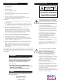
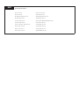
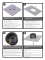
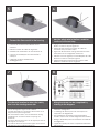
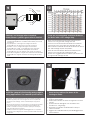
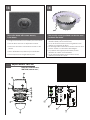
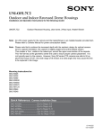
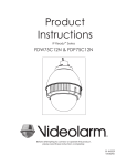
Installation and Operation Instructions
Before attempting to connect or operate this product, please
read these instructions completely.
RM7
Vandal Resistant, Recessed Ceiling Mounted Dome Camera Enclosure
RM7C2N........IP Network Ready 7” Vandal-Resistant Outdoor Recessed dome housing, with recessed ceiling mount, clear dome, with 24Vac transformer
RM7T2N.........IP Network Ready 7” Vandal-Resistant Outdoor Recessed dome housing, with recessed ceiling mount, tinted dome, with 24Vac transformer
IRM7C2N........IP Network Ready 7” Vandal-Resistant Indoor Recessed dome housing, with recessed ceiling mount, clear dome, with 24Vac transformer
IRM7T2N........IP Network Ready 7” Vandal-Resistant Indoor Recessed dome housing, with recessed ceiling mount, tinted dome, with 24Vac transformer
Substitute “C” (Clear dome) for “T” (Tinted dome) version
Moog Inc.
Sensor and Surveillance Systems
© 2013, Moog Inc. All Rights Reserved
3650 Woodhead Drive Northbrook, IL. USA 60062
+1.847.498.0700 Fax: +1.847.498.1258 www.moogS3.com
81-IN5394 111313
IMPORTANT SAFEGUARDS
1
Read these instructions.
2
Keep these instructions.
3
Heed all warnings
4
Follow all instructions.
5
Do not use this apparatus near water.
6
Clean only with damp cloth.
7
CAUTION
RISK OF ELECTRIC SHOCK
DO NOT OPEN
Do not block any of the ventilation openings. Install in accordance with the
manufacturers instructions.
8
9
SAFETY PRECAUTIONS
Cable Runs- All cable runs must be within permissible distance.
CAUTION: TO REDUCE THE RISK OF
ELECTRIC SHOCK, DO NOT REMOVE
COVER ( OR BACK). NO USER- SERVICEABLE PARTS INSIDE. REFER SEVICING
TO QUALIFIED SERVICE PERSONNEL.
Mounting - This unit must be properly and securely mounted to a supporting
structure capable of sustaining the weight of the unit.
Accordingly:
a. This installation should be made by a qualified service person and should conform
to all local codes.
b. Care should be exercised to select suitable hardware to install the unit, taking into
account both the composition of the mounting surface and the weight of the unit.
10 Do not install near any heat sources such as radiators, heat registers, stoves, or other
apparatus ( including amplifiers) that produce heat.
11 Do not defeat the safety purpose of the polarized or grounding-type plug. A
polarized plug has two blades with one wider than the other. A grounding type
plug has two blades and a third grounding prong. The wide blade or the third
prong are provided for your safety. When the provided plug does not fit into your
outlet, consult an electrician for replacement of the obsolete outlet.
12 Protect the power cord from being walked on or pinched particularly at plugs,
convenience receptacles, and the point where they exit from the apparatus.
13 Only use attachment/ accessories specified by the manufacturer.
14 Use only with a cart, stand, tripod, bracket, or table specified by the manufacturer,
or sold with the apparatus. When a cart is used, use caution when moving the cart/
apparatus combination to avoid injury from tip-over.
15 Unplug this apparatus during lighting storms or when unused for long periods of time.
16 Refer all servicing to qualified service personnel. Servicing is required when the
apparatus has been damaged in any way, such as power-supply cord or plug is
damaged, liquid has been spilled of objects have fallen into the apparatus, the
The lightning flash with an arrowhead symbol,
within an equilateral triangle, is intended to
alert the user to the presence of non-insulated
“dangerous voltage” within the product’s
enclosure that may be of sufficient magnitude
to constitute a risk to persons.
Este símbolo se piensa para alertar al usuario a la presencia
del “voltaje peligroso no-aisIado” dentro del recinto de los
productos que puede ser un riesgo de choque eléctrico.
Ce symbole est prévu pour alerter I’utilisateur à la presence
“de la tension dangereuse” non-isolée dans la clôture de
produits qui peut être un risque de choc électrique.
Dieses Symbol soll den Benutzer zum Vorhandensein der
nicht-lsolier “Gefährdungsspannung” innerhalb der
Produkteinschließung alarmieren die eine Gefahr des
elektrischen Schlages sein kann.
Este símbolo é pretendido alertar o usuário à presença “di
tensão perigosa non-isolada” dentro do cerco dos produtos
que pode ser um risco de choque elétrico.
Questo simbolo è inteso per avvertire I’utente alla presenza
“di tensione pericolosa” non-isolata all’interno della
recinzione dei prodotti che può essere un rischio di scossa
elettrica.
apparatus has been exposed to rain or moisture, does not operate normally, or
has been dropped.
Be sure to periodically examine the unit and the supporting structure to make sure that the integrity
of the installation is intact. Failure to comply with the foregoing could result in the unit separating
from the support structure and falling, with resultant damages or injury to anyone or anything struck
by the falling unit.
UNPACKING
Unpack carefully. Electronic components can be
damaged if improperly handled or dropped. If an item
appears to have been damaged in shipment, replace
it properly in its carton and notify the shipper.
Be sure to save:
1 The shipping carton and packaging material.
They are the safest material in which to make future
shipments of the equipment.
2 These Installation and Operating Instructions.
SERVICE
If technical support or service is needed, contact us at
the following number:
TECHNICAL SUPPORT
AVAILABLE 24 HOURS
1 - 800 - 554 -1124
The exclamation point within an equilateral
triangle is intended to alert the user to
presence of important operating and
maintenance (servicing) instructions in the
literature accompanying the appliance.
Este símbolo del punto del exclamation se piensa para
alertar al usuario a la presencia de instrucciones importantes
en la literatura que acompaña la aplicación.
Ce symbole de point d’exclamation est prévu pour alerter
l’utilisateur à la presence des instructions importantes dans
la littérature accompagnant l’appareil.
Dieses Ausruf Punktsymbol soll den Benutzer zum
Vorhandensein de wichtigen Anweisungen in der Literatur
alarmieren, die das Gerät begleitet.
Este símbolo do ponto do exclamation é pretendido alertar o
usuário à presença de instruções importantes na literatura
que acompanha o dispositivo.
Questo simbolo del punto del exclamaton è inteso per
avvertire l’utente alla presenza delle istruzioni importanti nella
letteratura che accompagna l'apparecchio.
MADEIN
USA
BUY AMERICA COMPLIANT • COUNTRY OF ORIGIN U.S.A.
Product Warranty Registration
Register Your Products Online
www.moogS3.com/technical-support/product-registration
Moog values your patronage. We are solely committed to providing you with the highest quality products and
superior customer service. With 3-Year and 5-Year warranties (depending on the product purchased) we stand
behind every product we sell.
See full warranty details at www.moogS3.com/technical-support/warranty-plan/
:
• Simple and Trouble-Free RMA process
• Product / software updates
• Special promotions
• Eliminate the need to archive purchase documents such as receipts, purchase orders, etc.
Limited Warranty for Moog Products
Moog - Decatur Operations, subsequently referred to as “Manufacturer,” warrants these products to be free from defects in material or workmanship as follows:
PRODUCT CATEGORY
PARTS \ LABOR
All Enclosures and Electronics
Five (5) Years
Accessory Brackets
Five (5) Years
Controllers
Three (3) Years
Power Supplies / IR Illuminators
Three (3) Years
Poles / PolEvators / CamEvator
Three (3) Years
Warrior Series™ / Q-View™
Three (3) Years
™
Three (3) Years 6 months if used in auto scan / tour operation
SView Series
™
DeputyDome , NiteTrac , Igloo Dome, PurgeDome
Three (3) Years 6 months if used in auto scan / tour operation
EXO Series™ Dome and Fixed Camera Systems*
Three (3) Years 6 months if used in auto scan / tour operation
EXO Series™ GeminEye Visible and Thermal Camera Systems
One (1) Year
™
™
™
During the labor warranty period, to repair the Product, Purchaser will either return the defective product, freight prepaid, or deliver it to Manufacturer at Moog Decatur
Operations, 2525 Park Central Boulevard, Decatur, Georgia, 30035. The Product to be repaired is to be returned in either its original carton or a similar package affording
an equal degree of protection with a RMA # (Return Materials Authorization number) displayed on the outer box or packing slip. To obtain a RMA# you must contact our
Technical Support Team at 800.554.1124, extension 101. Manufacturer will return the repaired product freight prepaid to Purchaser. Manufacturer is not obligated to
provide Purchaser with a substitute unit during the warranty period or at any time. After the applicable warranty period, Purchaser must pay all labor and/or parts charges.
The limited warranty stated in these product instructions is subject to all of the following terms and conditions.
TERMS AND CONDITIONS
1. NOTIFICATION OF CLAIMS: WARRANTY SERVICE: If Purchaser believes that the Product is defective in material or workmanship, then written notice with an explanation
of the claim shall be given promptly by Purchaser to Manufacturer. All claims for warranty service must be made within the warranty period. If after investigation,
Manufacturer determines the reported problem was not covered by the warranty, Purchaser shall pay Manufacturer for the cost of investigating the problem at its then
prevailing per incident billable rate. No repair or replacement of any Product or part thereof shall extend the warranty period of the entire Product. The specific warranty on
the repaired part only shall be in effect for a period of ninety (90) days following the repair or replacement of that part or the remaining period of the Product parts warranty,
whichever is greater.
2. EXCLUSIVE REMEDY: ACCEPTANCE: Purchaser’s exclusive remedy and Manufacturer’s sole obligation is to supply (or pay for) all labor necessary to repair any Product
found to be defective within the warranty period and to supply, at no extra charge, new or rebuilt replacements for defective parts.
3. EXCEPTIONS TO LIMITED WARRANTY: Manufacturer shall have no liability or obligation to Purchaser with respect to any Product requiring service during the warranty
period which is subjected to any of the following: abuse, improper use, negligence, accident, or acts of God (i.e., hurricanes, earthquakes), modification, failure of the
end-user to follow the directions outlined in the product instructions, failure of the end-user to follow the maintenance procedures recommended by the International Security
Industry Organization, written in product instructions, or recommended in the service manual for the Product. Furthermore, Manufacturer shall have no liability where a
schedule is specified for regular replacement or maintenance or cleaning of certain parts (based on usage) and the end-user has failed to follow such schedule; attempted
repair by non-qualified personnel; operation of the Product outside of the published environmental and electrical parameters, or if such Product’s original identification
(trademark, serial number) markings have been defaced, altered, or removed. Manufacturer excludes from warranty coverage Products sold AS IS and/or WITH ALL FAULTS
and excludes used Products which have not been sold by Manufacturer to the Purchaser. All software and accompanying documentation furnished with, or as part of the
Product is furnished “AS IS” (i.e., without any warranty of any kind), except where expressly provided otherwise in any documentation or license agreement furnished with
the Product. ANY COST ASSOCIATED WITH REMOVAL OF DEFECTIVE PRODUCT AND INSTALLATION OF REPLACEMENT PRODUCT IS NOT INCLUDED IN THIS WARRANTY.
4. PROOF OF PURCHASE: The Purchaser’s dated bill of sale must be retained as evidence of the date of purchase and to establish warranty eligibility.
DISCLAIMER OF WARRANTY
EXCEPT FOR THE FOREGOING WARRANTIES, MANUFACTURER HEREBY DISCLAIMS AND EXCLUDES ALL OTHER WARRANTIES, EXPRESS OR IMPLIED, INCLUDING, BUT
NOT LIMITED TO ANY AND/OR ALL IMPLIED WARRANTIES OF MERCHANTABILITY, FITNESS FOR A PARTICULAR PURPOSE AND/OR ANY WARRANTY WITH REGARD TO ANY
CLAIM OF INFRINGEMENT THAT MAY BE PROVIDED IN SECTION 2-312(3) OF THE UNIFORM COMMERCIAL CODE AND/OR IN ANY OTHER COMPARABLE STATE STATUTE.
MANUFACTURER HEREBY DISCLAIMS ANY REPRESENTATIONS OR WARRANTY THAT THE PRODUCT IS COMPATIBLE WITH ANY COMBINATION OF NON-MANUFACTURER
PRODUCTS OR NON-MANUFACTURER RECOMMENDED PRODUCTS PURCHASER MAY CHOOSE TO CONNECT TO THE PRODUCT.
LIMITATION OF LIABILITY
THE LIABILITY OF Manufacturer, IF ANY, AND PURCHASER’S SOLE AND EXCLUSIVE REMEDY FOR DAMAGES FOR ANY CLAIM OF ANY KIND WHATSOEVER, REGARDLESS
OF THE LEGAL THEORY AND WHETHER ARISING IN TORT OR CONTRACT, SHALL NOT BE GREATER THAN THE ACTUAL PURCHASE PRICE OF THE PRODUCT WITH RESPECT
TO WHICH SUCH CLAIM IS MADE. IN NO EVENT SHALL MANUFACTURER BE LIABLE TO PURCHASER FOR ANY SPECIAL, INDIRECT, INCIDENTAL, OR CONSEQUENTIAL
DAMAGES OF ANY KIND INCLUDING, BUT NOT LIMITED TO, COMPENSATION, REPLACEMENT LABOR COSTS, REIMBURSEMENT, OR DAMAGES ON ACCOUNT OF THE LOSS
OF PRESENT OR PROSPECTIVE PROFITS OR FOR ANY OTHER REASON WHATSOEVER.
* NOTE
Moog will repair or replace, at its option, any equipment which is damaged by transient voltage surge/spike or lightning strike (an “Occurrence”), while properly connected
to wired AC power line with protective ground. Any repair or modification of the equipment done by someone other than Moog voids the warranty.
Form 500-911 081913
INDEX
Specific Camera Instructions:
Axis 213: Block 15
Elmo PTC 401: Block 33
Axis 214: Block 16
JVC VN-C30U: Block 34
Axis 231D and 232D: Blocks 17-21
JVC VN-625U/TK-625U: Block 35
Axis 233D: Blocks 22-26
JVC VN-C655U: Block 36
Canon VB-C10R: Block 27
Panasonic BB-HCM381/KX-HMC280: Block 37
Canon VB-C50IR: Block 28
Pixord 261/262: Block 38
Canon VC-C4R and VC-C50IR: Block 29
Sony SNC-RZ25: Block 39
Elmo PTC 200C: Block 30
Sony SNC-RZ30: Block 40
Elmo PTC 201: Block 31
Sony SNC-RZ50: Block 41
Elmo PTC 400C: Block 32
Toshiba IK-WB21A: Block 42
!
English
Español
Electrical Specifications
Power 24VAC
Class 2 Only
24 VAC
1.8 Amps
54 Watts
Total Power: 54 Watts
Accessories:
Camera Power:
Tools Required:
RM7C2N
RM7C2 (OUTDOOR ONLY)
Heater: 25 Watts/Blower: 1 Watt
28 Watts
.100” Flat Head Screwdriver
Phillips Head Screwdriver
Note: IRM7CN includes no accessories
24 VAC
1.8 amperios
54 vatios
Energía Total: 54 vatios
Accesorios:
Calentador: 25 Watts/Blower: 1 vatio
Energía De la Cámara fotográfica:
28 vatios
Las Herramientas Requirieron: Destornillador Principal Plano Del 100"
Destornillador Principal Phillips
Nota: IRM7CN no incluye ningún accesorio
24 VCA
1.8 ampères
54 watts
Puissance Totale : 54 watts
Accessoires :
Réchauffeur : 25 Watts/Blower : 1 watt
Puissance D'Appareil-photo :
28 watts
Français Les Outils besoin :
Tournevis Principal Plat De 100"
Tournevis Principal Phillips
Note : IRM7CN n'inclut aucun accessoire
24 VAC
1.8 Ampere
54 Watt
Gesamtenergie: 54 Watt
Zusatzgeräte:
Heizung: 25 Watts/Blower: 1 Watt
Kamera-Energie:
28 Watt
Deutsch Werkzeuge Erforderten: 100"Flacher Hauptschraubenzieher
Kreuzkopfhauptschraubenzieher
Anmerkung: IRM7CN schließt keine Zusatzgeräte mit ein
24 VAC
1.8 ampères
54 watts
Poder Total: 54 watts
Acessórios:
Calefator: 25 Watts/Blower: 1 watt
Poder Da Câmera:
28 watt
Portuguese As Ferramentas Requereram: Chave de fenda Principal Lisa Do 100"
Chave de fenda Principal Phillips
Nota: IRM7CN não inclui nenhum acessório
Italiano
24 VAC
1.8 ampère
54 watt
Alimentazione Totale: 54 watt
Accessori:
Riscaldatore: 25 Watts/Blower: 1 watt
Alimentazione Della Macchina fotografica:
28 watt
Attrezzi Richiesti:
Cacciavite Capo Piano Del 100"
Cacciavite Capo "phillips"
Nota: IRM7CN non include accessori
IRM7C2N (INDOOR ONLY)
24 VAC
No power options provided.
Power required for camera only.
24 VAC
Ningunas opciones de la energía proporcionaron.
Energía requerida para la cámara fotográfica solamente.
24 VCA
Option de puissance n'a pas fourni.
Puissance requise pour l'appareil-photo seulement.
24 VAC
Keine Energie Wahlen stellten zur Verfügung.
Energie erfordert für nur Kamera.
24 VAC
Nenhumas opções do poder fornecidas.
Poder requerido para a câmera somente.
24 VAC
Nessun'opzione di alimentazione ha fornito.
Alimentazione richiesta per la macchina fotografica soltanto.
Contents of Box
1
2
10.375”
A box cutter or jigsaw can be used for
cutting the circle.
Using the provided template, mark the
ceiling tile for the cutout.
• Con la plantilla proporcionada, cortar el azulejo del
techo para el agujero.
• En utilisant le calibre fourni, marquez la tuile de
plafond pour le coupe-circuit.
• Mit der zur Verfügung gestellten Schablone
kennzeichnen Sie die Decke Fliese für den Ausschnitt.
• Usando o molde fornecido, marque a telha do teto
para o entalhe.
• Usando la mascherina fornita, contrassegni le
mattonelle del soffitto per il ritaglio.
3
Add spacers to the plate in order to appropriately position the camera, see specific camera.
• Un cortador o un rompecabezas de la caja se
puede utilizar para cortar el círculo.
• Un coupeur ou une scie sauteuse de boîte peut
être utilisé pour couper le cercle.
• Ein Kastenscherblock oder -tischlerbandsäge
können für den Schnitt des Kreises benutzt werden.
• Um cortador ou um jigsaw da caixa podem ser
usados cortando o círculo.
• Una taglierina o un jigsaw della scatola può essere
utilizzato per il taglio del cerchio.
4
Place the housing in the tile and secure the
outer tabs.
• Agregue los espaciadores a la placa para colocar apropiada-
• Coloque la cubierta en el azulejo y asegure las
lengüetas externas.
•
• Placez le logement dans la tuile et fixez les étiquettes
externes.
•
•
•
mente la cámara fotográfica, vea la cámara fotográfica
específica.
Ajoutez les entretoises au plat afin de placer convenablement
l'appareil-photo, voyez l'appareil-photo spécifique.
Fügen Sie Distanzscheiben der Platte hinzu, um die Kamera
passend in Position zu bringen, sehen Sie spezifische Kamera.
Adicione espaçadores à placa a fim posicionar apropriadamente a câmera, veja a câmera específica.
Aggiunga i distanziatori alla piastra per posizionare giustamente la macchina fotografica, veda la macchina fotografica
specifica.
• Legen Sie das Gehäuse in die Fliese und sichern Sie
die äußeren Vorsprünge.
• Coloque a carcaça na telha e fixe as abas exteriores.
• Disponga l'alloggiamento nelle mattonelle ed assicuri
le linguette esterne.
5
6
Connect the flex conduit to the housing.
• Conecte el conducto de la flexión con la
cubierta.
• Reliez le conduit de câble au logement.
• Schließen Sie das Flexrohr an das Gehäuse an.
• Conecte a canalização do cabo flexível à
carcaça.
• Colleghi il condotto della flessione
all'alloggiamento.
7
Add the safety wire to the flex conduit or
continue to the next step.
• Agregue el alambre de seguridad al conducto de la
flexión o continúe al paso siguiente.
• Ajoutez le fil de sûreté au conduit de câble ou
continuez à la prochaine étape.
• Fügen Sie die Sicherheit Leitung dem Flexrohr hinzu
oder fahren Sie zum folgenden Schritt fort.
• Adicione o fio de segurança à canalização do cabo
flexível ou continue à etapa seguinte.
• Aggiunga il legare di sicurezza al condotto della
flessione o continui al punto seguente.
8
Power
28 Watts
Heater/ Blower
Heater/ Blower
The alternate location to attach the safety
wire is on the housing secure tab.
• La localización alterna para unir el alambre de seguridad
está en la lengüeta segura de la cubierta.
• L'endroit alternatif pour attacher le fil de sûreté est sur
l'étiquette bloquée de logement.
• Die wechselnde Position, zum der Sicherheit Leitung
anzubringen ist auf dem sicheren Vorsprung des
Gehäuses.
• A posição alterna para unir o fio de segurança está na
aba segura da carcaça.
• La posizione alternata per fissare il legare di sicurezza è
sulla linguetta sicura dell'alloggiamento.
26 Watts
Wiring the dome can be completed by
referring to the diagram.
• Atar con alambre la bóveda puede ser terminada
refiriendo al diagrama.
• Le câblage du dôme peut être accompli en se
rapportant au diagramme.
• Das Verdrahten der Haube kann durchgeführt
werden, indem man auf das Diagramm sich bezieht.
• Wiring a abóbada pode ser terminado consultando
ao diagrama.
• Legare la cupola può essere completato riferendosi
allo schema.
9
10
Green
Yellow
Orange
,5
22
Accessory
Power
,75
20
1,0
18
1,5
16
2,5
14
4
12
6
10
MM2
AWG
Camera
Power
Red
Camera = red & orange wires to terminal
Heater/Blower = yellow & green wires to terminal
• Cámara fotográfica = alambres rojos y anaranjados al
terminal Heater/Blower = alambres del amarillo y del verde
al terminal
• Appareil-photo = fils rouges et oranges à la borne
Heater/Blower = fils de jaune et de vert à la borne
• Kamera = rote u. orange Leitungen zum Anschluß
Heater/Blower = Gelb- u. Grünleitungen zum Anschluß
• Câmera = fios vermelhos & alaranjados ao terminal
Heater/Blower = fios do amarelo & do verde ao terminal
• Macchina fotografica = legare rossi & arancioni al terminale
Heater/Blower = legare di verde & di colore giallo al terminale
11
The beam angle may be adjusted on the bottom of the unit.
Install
the camera in the housing and complete
wiring applications. See camera specifications.
• Instale la cámara fotográfica en la cubierta y termine los usos del
cableado. Vea las especificaciones de la cámara fotográfica.
• Installez l'appareil-photo dans le logement et accomplissez les
applications de câblage. Voir les caractéristiques d'appareilphoto.
• Bringen Sie die Kamera in das Gehäuse an und führen Sie Verdrahtung Anwendungen durch. Sehen Sie Kameraspezifikationen.
• Instale a câmera na carcaça e termine aplicações da fiação.
Veja especificações da câmera.
• Installi la macchina fotografica nell'alloggiamento e completi le
applicazioni dei collegamenti. Veda le specifiche della macchina
fotografica.
The
beam
angle may be adjusted
the
These
are recommended
maximumon
distances
bottom
of with
the unit.
for 24VAC
a 10% voltage drop.
• Éstos se recomiendan las distancias máximas para
24VAC con una gota del voltage del 10%.
• Ceux-ci sont recommandés des distances maximum
pour 24VAC avec une baisse de volatage de 10%.
• Diese werden maximale Abstände für 24VAC mit einem
das 10% volatage Tropfen empfohlen.
• Estes são recomendados distâncias máximas para
24VAC com uma gota do volatage de 10%.
• Questi sono suggeriti distanze massime per 24VAC con
una goccia di volatage di 10%.
12
The beam
angle may
be adjusted
on the
Hook
the lanyard
from the
dome to the
housing
as the
shown.
bottom of
unit.
• Enganche el acollador de la bóveda a la cubierta
según lo demostrado.
• Accrochez la lanière du dôme au logement comme
montré.
• Spannen Sie die Abzuglinie von der Haube zum
Gehäuse an, wie gezeigt.
• Enganche o colhedor da abóbada à carcaça
como mostrada.
• Agganci la cordicella dalla cupola all'alloggiamento
come indicato.
13
14
beamthe
angle
may
bescrews
adjusted
on the bttom
Secure
dome
with
already
inothe
dome.
the unit.
The security screws provided can also be used
to attach the dome.
• Los tornillos de la seguridad proporcionados se pueden
también utilizar para unir la bóveda.
• Les vis de sécurité fournies peuvent également être
utilisées pour attacher le dôme.
• Die bereitgestellten Sicherheit Schrauben können auch
benutzt werden, um die Haube anzubringen.
• Os parafusos da segurança fornecidos podem
também ser usados unir a abóbada.
• Le viti di sicurezza fornite possono anche essere
utilizzate per fissare la cupola.
• Asegure la bóveda con los tornillos ya en la bóveda.
• Fixez le dôme avec des vis déjà dans le dôme.
• Sichern Sie die Haube mit Schrauben bereits in der
Haube.
• Fixe a abóbada com parafusos já na abóbada.
• Fissi la cupola con le viti già nella cupola.
Replacement Parts List
1
2
3
4
5
6
7
8
9
10
11a
11b
12
13a
13b
14
15
16
17
RM7C2N (OUTDOOR ONLY)
IRM7C2N (INDOOR ONLY)
2
1
DESCRIPTION
REPLACEMENT PART NUMBER
RP30VL2873
RP95FSVP05
RP30VL2733
RP90BTRP61
RPVL2204
RP96RSORG11
Metal Housing Top
½” Rubber Conduit Plug
Lanyard Clip
8 x 32 x 3’” Bolt (3)
Ceiling Spring Clips (3)
Trim Ring O-Ring
N/S
Spring Lanyard
Dome Clamping Ring
Aluminum Trim Ring
Captive Phillips Screws (3)
Captive Security Screws (3)
Dome Gasket
Clear Polycarbonate Dome and Gasket
Tinted Polycarbonate Dome and Gasket
Electrical Packet
Housing Hardware Packet A
Housing Hardware Packet B
Security Tool and Screw Packet
RP95FSSL05
RPFD703
RP30VL2884
RP90BT3007
RP90BT2975
RP96GK2558
RPFD7C
RPFD7T
RPPKE1100
RPPKH2090
RPPKH2071
RPPKH2110
4
(1)
6
(1)
8
9
(1)
(3)
12
(1)
14
(1)
(1)
10
11
(4)
(1)
3
5
(3)
(1)
(1)
(1)
(4)
(4)
(4)
(4)
(4)
(3)
(1)
(4)
(3)
(2)
(3)
16
15
13
(2)
(2)
(4)
(1)
(8)
(1)
17
(2)