1
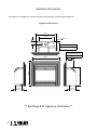
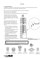
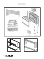
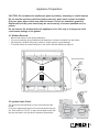
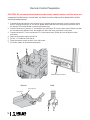
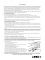
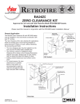
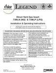
Direct Vent Gas Insert
Model 739DVN (Natural Gas)
Model 739DVP (Propane Fuel)
Installation and Owner’s Manual
INSTALLER: Leave this manual with the appliance.
CONSUMER: Retain this manual for future reference.
FOR YOUR SAFETY
PLEASE READ THESE INSTRUCTIONS
CAREFULLY BEFORE INSTALLING AND
OPERATING THE APPLIANCE.
DO NOT store or use gasoline or any other WARNING: If the information in these
flammable vapors or liquids in the vicinity instructions is not followed exactly a fire
or explosion may result causing property
of this or any other appliance.
damage, personal injury or loss of life.
IF YOU SMELL GAS:
- Do not try to light any appliance.
Installation and service must be performed
- Open windows.
by a qualified installer, service agency or
- Do not touch electrical switches.
the gas supplier.
- Do not use any phone in your building.
- Extinguish any open flame.
WARNING: This product must be installed
- Immediately call your gas supplier from by a licensed plumber or gas fitter when
a neighbor’s phone. Follow the gas
installed within the Commonwealth of
supplier’s instructions.
Massachusetts. This appliance is suitable
- If you cannot reach the gas supplier,
for installation in a bedroom or bed-sitting
call the fire department.
room.
This appliance may be installed in an aftermarket permanently located, manufactured
(mobile) home, where not prohibited by local codes. This appliance is only for use with
the type of gas indicated on the rating plate. This appliance is not convertible for use
with other gases, unless a certified kit is used.
Made in Canada by Miles Industries Ltd.
190-2255 Dollarton Highway, North Vancouver, BC, Canada V7H 3B1
www.milesfireplaces.com
4000072-14
©2007, Miles Industries Ltd. All rights reserved.
Table of Contents
Introduction ............................................................................................... 3
Appliance Dimensions ............................................................................. 4
Safety Information .................................................................................... 5
Specifications............................................................................................ 7
Planning ..................................................................................................... 8
Clearances ................................................................................................. 9
Venting ..................................................................................................... 11
Pack Contents ......................................................................................... 13
Appliance Preparation ............................................................................ 15
Remote Control Preparation .................................................................. 16
Gas Supply .............................................................................................. 17
Panel Installation .................................................................................... 18
Log Installation ....................................................................................... 19
Burner & Pilot Operation ........................................................................ 21
Window Refitting ..................................................................................... 21
Trim Installation ...................................................................................... 22
Final Checks ............................................................................................ 23
Operational Warnings ............................................................................. 24
Lighting Instructions .............................................................................. 25
Maintenance ............................................................................................ 26
Programmable Remote Control ............................................................. 28
Venting Options ...................................................................................... 30
Warranty................................................................................................... 31
The information contained in this installation manual is believed to be correct at the time of printing. Miles
Industries Ltd. reserves the right to change or modify any information or specifications without notice. Miles
Industries Ltd. grants no warranty, implied or stated, for the installation or maintenance of your heater, and
assumes no responsibility for any consequential damage(s).
2
Introduction
Thank you for purchasing the Valor 739 Direct Vent insert. This high quality unit is specifically designed to
be used where installations are restricted by the size of the fireplace. It is our goal to satisfy every Valor
customer. This owner’s manual explains the steps required to safely assemble, install, operate, and maintain
your new appliance.
Options
The model 739 base unit is supplied equipped for use with either natural gas 739DVN or propane fuel
739DVP.
Appliance Styles
Standard metal front, black
Cast iron front, black
FenderFire Double Doors Front
FenderFire Single Door Front
Kit #741SFB
Kit #742CFB
Kit #743FVI
Kit #744FVI
Optional Outer Trims
3-sided Contour Trim Kit
3-sided Deluxe Trim Kit
4-sided Contour Trim Kit
4-sided Deluxe Trim Kit
Kit #746
Kit #747
Kit #748
Kit #749
Additional Optional Features
Circulating Fan Kit #755CFK
Variable speed and temperature control. It is designed to boost the natural convection process through the
appliance. It may be fitted before the fireplace is installed or retrofitted at a later date.
Natural Gas Conversion Kit #608NGK
For conversion from propane to natural gas. Intended primarily for post-installation conversion in areas
where natural gas was not available at the time of initial installation.
Venting Options
Direct Vent Installations
One or more of the accessories listed on page 30 must be used for each installation. See vent installation
section for details..
3
Appliance Dimensions
See section on installation for details regarding clearances and mantel height allowances.
Appliance Dimensions
28-3/8”
19-1/2”
R 1/12”
2-5/8”
12-5/8” with Contour Outer Trim
12” with Deluxe Outer Trim
10” with Contour Outer Trim
9-3/8” with Deluxe Outer Trim
9-1/4”
Gas Line
20”
26-5/8”
36-1/2”
7-3/8”
Electrical
** See Page 9 for clearance information **
4
Safety Information
If this appliance is not properly installed, a house fire or explosion may result. For your
safety, follow the installation directions. Contact local building or fire officials about
restrictions and installation requirements in your area. Please read this entire manual
before you install and use your new appliance. Failure to follow instructions may result
in property damage, bodily injury or death.
Safe installation and operation always require common sense. We are also required by
Canadian and ANSI safety standards to point out the following:
Installation and repair should be done by
a qualified service person. The appliance
should be inspected before use and at
least annually by a professional service
person. More frequent cleaning may
be required due to excessive lint from
carpeting, bedding material, et cetera.
Clothing or other flammable materials
should not be placed on or near the
appliance.
It is imperative that control
compartments, burners and circulating
air passageways of the appliance are kept
clean.
The flexible cord provided must be
connected to a line voltage electrical
supply.
Due to high temperatures, the appliance
should be located out of traffic and away
from furniture and draperies.
Do not use this heater if any part has been
under water. Immediately call a qualified
service technician to inspect the heater
and to replace any part of the control
system and any gas control which has
been under water.
The appliance area must be kept free from
combustible materials, gasoline and other
flammable vapors and liquids.
WARNING
HOT GLASS WILL
CAUSE BURNS.
DO NOT TOUCH GLASS
UNTIL COOLED.
NEVER ALLOW CHILDREN
TO TOUCH GLASS.
Any safety screen or guard removed
for servicing of a room heater must be
replaced prior to operating the appliance.
Never vent the appliance into other rooms
or buildings. The appliance must be
vented only to the outside.
This appliance must not be connected to
a chimney flue serving a separate solidfuel burning appliance.
Children and adults should be alerted to
the hazards of high surface temperatures
and should stay away to avoid burns or
clothing ignition.
Young children should be carefully
supervised when they are in the same
room as the appliance.
Provision for adequate combustion and
ventilation air must be provided.
We recommend that our gas
hearth products be installed
and serviced by professionals
who are certified in the
United States by NFI (National
Fireplace Institute®).
5
Safety Information
NOTE: Always allow adequate clearance around air openings into the combustion chamber and
maintain accessibility clearances for servicing and proper operation.
2.1 General Safety (Home Owner)
3.1 Planning Your Installation
Cleaning. To clean the appliance, make sure it
is off and cold. Then remove the logs and use a
vacuum to clean the burner and air openings in
the bottom and back of the appliance. Replace the
logs.
Fire Extinguisher. Every home should have at
least one fire extinguisher. An approved Class
A-B-C extinguisher should be mounted on the wall
near an exit and close to the appliance, but not so
close that accessibility to the extinguisher could
be blocked by a fire. Your local Fire Department
can advise you concerning the most appropriate
location.
Smoke Detectors & Carbon Monoxide
Detectors. Install at least one smoke detector on
each floor of your home to ensure your safety. It
should be located away from the gas appliance
and close to the sleeping areas. Follow the smoke
detector manufacturer’s placement installation
and maintenance instructions. Your local Fire
Department may provide assistance in selecting
smoke detectors and carbon monoxide detectors.
It is strongly recommended, for your family’s
protection, that a carbon monoxide detector be
placed in all homes that utilize gas in any form.
Please note the following key points regarding the
location of your appliance:
• A sufficient gas pressure is required to supply the
unit with a minimum inlet pressure.
• Allow adequate accessibility clearances for
servicing and proper operation.
• Allow adequate clearance to combustibles and
around air openings for combustion.
• A suitable power outlet is required to provide
power when fitted with a fan.
2.2 Safety for the Installer
• Wear gloves and safety glasses for protection.
• Exercise extreme caution when using ladders
or when on rooftops.
• Be aware of electric wiring locations in walls
and ceilings.
• Use a back support when doing any heavy
lifting.
2.3 Vent Safety
Venting must be installed according to local codes
and good venting practices.
2.4 Electrical Code
These appliances, when installed, must be
electrically grounded in accordance with local
codes or, in the absence of local codes, with the
National Electrical Code, ANSI/NFPA 70 or the
Canadian Electrical Code, CSA C22.1.
6
3.2 Listing and Codes
The Valor model 739 is listed and certified for
installation in the U.S.A. and Canada under the
following standards:
• ANSI Z21.88-2005 / CSA 2.33-2005 Vented Gas
Fireplace Heaters.
• CAN/CGA-2.17-M91, Gas-Fired Appliances for
Use at High Altitudes.
3.3 Installation Codes
This appliance must be installed in accordance with
local codes if any or, in the absence of local codes,
follow the National Fuel Gas Code, ANSI Z223.1 or
Natural Gas and Propane Installation Code, CAN
1-B149.
3.4 High Altitude Installation
When installing this appliance over 4,500 ft. (1,372
m) above sea level in Canada, the appliance must
be properly de-rated and installed according to local
codes; in the absence of local codes, it must be
installed in accordance with CAN/CGA-B149. In the
US, for installations above 2,000 ft., the appliance
must be installed in accordance with the current
National Fuel Gas Code, ANSI Z223.1/ NFPA 54.
Specifications
Note: Always check appliance label for correct information
MODEL 739
Natural Gas (NG)
Propane (LPG)
Manifold pressure
3.95 in. w.c. (0.98 kPa)
9.5 in. w.c. (2.37 kPa)
5.0 in. w.c. (1.25 kPa)
11.0 in. w.c. (2.75 kPa)
10.5 in. w.c. (2.6 kPa)
14.0 in. w.c. (3.5 kPa)
Orifice size
Bray CAT 82–650
Bray CAT 92–260
Maximum input rating
24,000 BTU/hr
24,000 BTU/hr
High altitude (US)
0–2,000 ft. (0–610 m) US
0–2,000 ft. (0–610 m) US
High altitude (Canada)
0–4,500 ft. (0–1,372 m) Can
0–4,500 ft. (0–1,372 m) Can
Electrical rating
120 V.A.C. System
120 V.A.C. System
Circulating fan
Variable Speed
Variable Speed
Vent system
3” approved flex
3” approved flex
Log set
Ceramic (6–Piece)
Ceramic (6–Piece)
Min. supply pressure for
purpose of input adjustment
Max. supply pressure for
purpose of input adjustment
7
Planning
5.1 Forward Planning
We recommend the following steps for installation.
1. Familiarize yourself with this manual.
2. Check the minimum install dimensions and vent installation.
3. Check your local install codes.
4. Check that you have all the parts and components necessary to complete the installation.
5. Check that the gas and electrical supplies are ready.
6. Prepare opening (clean chase, level base, etc.).
7. Install vent.
8. Install base unit and connect vent.
9. Install optional fan.
10. Connect gas and electrical supplies.
11. Install operational components and prepare for first test fire.
12. Check operation of unit.
13. Fit surround (optional) and front kit.
14. Take time to explain the operation of the appliance to the customer (most call backs are caused because
the customer does not understand the operation of the unit).
NOTE: THIS APPLIANCE MAY ONLY BE INSTALLED IN A SOLID-FUEL BURNING FIREPLACE WITH A
WORKING FLUE AND CONSTRUCTED OF NON-COMBUSTIBLE MATERIAL.
8
Clearances
6.1 Existing Fireplace (Masonry or Factory-Built)
The model 739 is intended for installation into masonry or listed factory-built fireplaces. Masonry fireplaces
must be built according to the requirements of the standards for chimneys, fireplaces, vents and solid-fuel
burning appliances, NFPA 211 (Latest Edition) or the applicable national, provincial, state or local codes. The
section 6.2 shows the minimum install dimensions for the model 739.
5”
5”
Distance from unit (engine) to combustible wall
Note: The model 739 is certified without requiring a hearth projection,
although local codes may require a minimum hearth projection.
Check that masonry step does not interfere with
install dimensions or vent pipe.
If mantel is combustible see section 6.2 for
allowable clearances.
Minimum width of fireplace opening at front = 28”
X = 12-5/8” for Contoured Outer Trims
X = 12 ” for Deluxe Outer Trims
Y = 20”
X
Y
9
Clearances
6.2 Combustible Mantel Clearance
Figure below shows minimum clearances to combustible mantles.
14” (355 mm)
8” (203 mm)
4” (102 mm)
1” (25 mm)
38”
(965 mm)
35”
(889 mm)
32”
(813 mm)
28”
(711 mm)
Note: Measure taken from underside of mantel to finished floor surface that the unit is sitting on.
6.3 Finishing Materials
Combustible materials: Material such as wood, compressed paper, plant fibers, plastics or any material
capable of igniting and burning, whether flame-proofed or not, plastered or un-plastered.
Non-Combustible Material: Material such as steel, iron brick, tile, concrete or materials that bear the UL
mark for zero (0) fire rating.
10
Venting
7.1 Vent Location
The vent terminal must be located through the roof.
This direct vent appliance is designed to operate when an undisturbed airflow hits the outside vent terminal
from any direction.
Check local codes for allowable vertical vent termination.
7.2 Venting Chart
Maximum vertical height
30 ft. (measured to bottom of termination)
Minimum vertical height
10 ft (measured to bottom of termination)
Maximum horizontal run
4 ft. (measured center to center of pipe)
Maximum offset angle
45° (sweeping bend to allow for obstructions)
30
28
4’ Max.
26
Venting Notes
Where possible, avoid joining flex pipes. If joints are required,
use the Dura-Vent 923F connector and seal joints with RTV
high temp sealant.
Four ft. horizontal is permissible to allow for routing around
masonry projections. Do not bend flex pipe over a 45° radius.
24
22
20
18
16
45˚
14
12
10
8
6
4
2
2 4
Horizontal Run (Feet) Max. 4’
11
Venting
7.3 Vent Installation
IMPORTANT: This appliance’s venting system is room sealed, which means that there should be no
provision to allow room air to be used in the combustion process.
Note: Use only 3” flex venting materials approved for masonry installations.
Planning Your Vent Installation
This type of direct vent system may only terminate in the following way:
Vertical termination using a Dura-Vent
3” adapter and cap (see Vent parts list).
There are limitations to the vertical and/or
horizontal lengths (see page 11 for venting
chart).
When calculating the length of the vent
pipe from the outlet of the appliance to
termination, allow for any offsets in the
chase and sufficient vertical height above
the roof.
1. Apply RTV sealant to the appliance’s
vent pipe and slide over the air intake
and exhaust pipes.
2. Secure using the 8 self-tapping screws
provided (4 per flex pipe).
3. Slide the unit into the opening, taking
care not to damage the liner (allow
enough slack for final surround
assembly).
4. At the top of the chimney, slide the
connector plate over the 2 flex liners.
5. Attach the termination cap to the flex
pipes using the 8 screws provided.
6. Seal the connector plate to the chimney
(fire cement).
Note: Inspect vent connection before
installing the trim surrounds.
WARNING: Failure to position the parts in accordance with these
diagrams or failure to use only parts specifically approved with
this appliance may result in property damage or personal injury.
Typical components used in shown example.
991 DV GS
Cap (High Wind)
12
980 DV GS
Cap (Low Profile)
930 DV GS
Extended Cap
2150 DV GS
Flex Connector
923GK DV GS
Chimney Liner Kit
923F DV GS
Appliance
Flex Connector
Pack Contents
#739DVN or #739DVP Engine Unit
#741SFB Standard Fronts (Alternative)
1
1
1
1
4
1
2
1
1
1
8
3
1 Frame and upper louver unit
1 Lower louver unit
Appliance engine unit fitted with window
Ceramic log pack (contains 6 pieces)
Ceramic brick pack (contains 3 pieces)
Remote control kit (handset, receiver and wires)
1.5 V AA batteries
9 V battery
Side shroud mounting brackets
Top shroud mounting bracket
Gas inlet pipe connection adapter
Rear log support
#8 screws
Cable clips
#742CFB Cast Iron Front (Alternative)
1 Top casting unit
1 Bottom casting unit
#755CFK Circulating Fan Kit (Additional
option)
Details are with the kit.
Take care when removing the contents from the packaging to prevent damage. Check that all the contents
are in the packs and are undamaged.
13
Pack Contents
739DVN or 739DVP Engine
Ceramic Brick Pack
Ceramic Log Set
Rear Log Rest
Engine Pack
741SFB Standard Metal Front
14
742CFB Cast Iron Front
Remote Control
Appliance Preparation
CAUTION: Do not abuse the appliance’s glass by striking, slamming or similar trauma.
Do not use the appliance with the window removed, glass panel cracked or broken.
Only use glass approved for use with this heater. Do not use substitute materials.
Replacement of the panel should only be carried out by a licensed qualified service
person.
Do not remove the window when the appliance is hot. Not only is it dangerous but it
could cause damage to the gasket.
9.1 Window Removal
• Remove the bottom center spring-loaded bolt.
• Turn the 5 remaining spring-loaded bolts 90 degrees to release the window from the firebox.
• Carefully lift the window away and put aside in a safe location to avoid damage.
• To reinstall, follow the instructions given in the section Window Refitting on page 21.
Spring-loaded bolts
2
1
9.2 Ignition Spark Check
The pilot burner and electrode unit are at the left end of the
burner.
Push in the lighting knob and turn it counter-clockwise through
the “IGN” position to “PILOT”. A spark should flash across from
the pilot electrode to the pilot burner shield as shown below.
Thermostat Knob
Gas Control Knob
15
Remote Control Preparation
CAUTION! Do not connect the batteries to the remote control receiver until the wires are
connected to the burner control unit, as short circuit could result in destruction of the
electrical components.
1. Connect the wiring harness to the receiver box by pushing the wire connector on to the receiver circuit
board. The plug will only go on one way so please ensure that the wires are pointing up and the slot in
the board is in line with the tab on the wiring harness plug.
2. Connect the wires “A” (with the “L” terminals) to the connectors “B” on the control valve. Please note that
the connectors are different sizes; the smaller one fits to the lower connection on the valve.
3. Connect the wires “C” to the connectors “D” on the control valve. (Either wire can be fitted to either
connector.)
4. Remove the remote control receiver lid.
5. Fit four 1.5 V batteries. Refit the lid.
6. Place the remote control receiver of the Velcro pad.
7. Fit the 9 V battery to the handset transmitter.
D
B
Remote control receiver
Receiver
Cable
Sensor Opening
LED (green)
C
16
A
Gas Supply
Only persons licensed to work with gas piping may make the necessary gas connection to this appliance.
You are now ready to hook up the gas supply. Be sure that gas plumbing instructions and all provincial and local
codes are carefully followed. Use approved flexible gas connections or rigid piping, depending on provincial
and local codes, to attach burner to gas supply. Be sure to use proper size gas supply line. Carefully check all
connections for gas leaks with soap and water solution.
Each installation must conform to all local, provincial and national codes. Refer to the national fuel gas code, local
zoning and code authorities for details on installation requirements.
11.1 Existing Gas Supply
Before interrupting the existing gas supply it is recommended that the following be checked:
•
•
Shut down all gas appliances and carry out a pressure test to insure there are no existing leaks on the system.
Before connecting the appliance to the gas supply line, double-check that the appliance you have purchased is designed
for the gas type you are using. The gas type markings are located on the certification label and also on the appliance’s gas
valve.
• Check the gas pressure to insure you will be able to supply the minimum inlet pressure for the appliance.
• Check your pipe sizing to insure that sufficient volume will be supplied to the appliance.
11.2 Gas Supply Installation
• Provide adequate clearance for proper installation and checking of the gas connections.
• Have your gas supplier or a qualified gas fitter run a gas supply line into the gas fireplace. The line must be properly sized
and fitted according to the installation codes. Upstream of the appliance supply connection, the fitter shall provide an easily
accessible manual shut-off valve.
•
The gas supply pipe should enter the appliance case through the opening at the rear left side. The supply pipe should be
connected to the appliance gas inlet pipe situated at the left side of the control unit. Supply line connection to the inlet pipe is
3/8 NPT.
•
If the circulating fan is to be installed, be aware that the supply pipe run inside the case should be at the same height as the
appliance inlet pipe in order to clear the fan. If intending to fit an internal isolating valve, check that it will be clear of the fan.
•
Use only new black iron or steel pipes or copper tubing if acceptable—check local codes. Note that in USA, copper tubing
must be internally tinned for protection against sulfur compounds.
•
•
Unions in gas lines should be of ground joint type.
Sealant used must be resistant to the action of all gas constituents including LP gas. Sealant should be applied lightly to
male threads to ensure excess sealant does not enter gas lines.
11.3 Pressure Testing the Supply Line for Leaks
• The appliance and its individual shut-off valve must be disconnected from the gas supply piping system during any pressure
testing of that system at test pressures in excess of 1/2 psig (3.5 kPa).
•
The appliance must be isolated from the gas supply piping system by closing its individual manual shut-off valve during any
pressure testing of the gas supply piping system at test pressures equal to or less than 1/2 psig (3.5 kPa). Failure to do
so will damage the appliance’s gas valve. Such damage is not covered by the manufacturer’s warranty.
•
When testing for leaks:
•
•
•
•
•
Make sure that the appliance is turned off.
•
•
Never use an open flame to check for leaks.
Open the manual shut-off valve.
Test for leaks by applying a liquid detergent or soap solution to all joints.
Bubbles forming indicate a gas leak.
Correct any leak detected immediately.
The pressure test tapping locations are shown in the diagram to the right.
A built-in non-adjustable regulator controls the burner manifold pressure. The
correct pressure range is shown in the Specifications section of this manual.
The pressure check should be made with the burner lit. See the lighting
instructions section for full operating details.
BE SURE TO TIGHTEN THE PRESSURE TAP SET-SCREW AFTER CHECKING THE PRESSURE.
CHECK ALL GAS CONNECTIONS FOR GAS LEAKS.
17
Panel Installation
12.1 Ceramic Panels Installation
1. Remove the Firebox Baffle by first removing 2
screws on the front flange and lifting the Baffle
towards you.
2. Position the Rear Ceramic Panel onto the Rear Brick
Panel Rest. The Panel will sit on the lower ledge and
be flat against the rear of the firebox.
Rear Brick Panel Rest
3. Slide the Left Ceramic Panel against the left side
of the firebox and up to the Rear Ceramic Panel.
The Panel will have to be angled to fit inside the
firebox. Position the Right Ceramic Panel in the
same fashion.
4. Re-install the Firebox Baffle fitting the rear flange
above the Rear Brick Panel Rest and fastening 2
screws provided on the front edge.
18
Log Installation
13.1 Ceramic Logs Installation
1. Install the Rear Log Rest supplied using 3 screws provided. See figure 13.1.
2. Place the Ash Bed in position. The projections at the front of the Ash Bed are positioned against the
sloping metal stops, immediately behind the burner. See figures 13.2, 13.8, 13.9.
3. Place the Rear Log in position. Place the Log on the 2 pins on the top left and right of the Ash Bed. See
figure 13.3.
4. Place the Front Log at the front of the firebox locating it on the front support. See figure 13.4.
5. Place the Left Side Center Log in position, locating the thick part on the left side of the Ash Bed on the 2
pins provided, with its “nose” resting on top of the Ash Bed center projection. See figure 13.5.
6. Identify the Right Side Center ‘Y’ log. Place the Right Side Center Y Log in position, locating the thick
part on the right side of the Ash Bed on to the pin provided with its “nose” located on the single pin. See
figure 13.6.
7. Install the Cross Twig by first mounting the rear of the Cross Twig on the pin situated on the top of the
Rear Log near the center. Then, move the front of the Cross Twig until it finds its location in the cradle
provided in the Front Log. See figure 13.7.
19
Log Installation
13.6
13.1
Rear Log Rest
Right Center Twig
13.2
13.7
Rear Log Pins
Ash Bed
Cross Twig
13.3
Rear Log
13.8
Left Center
Log Pins
See no. 2
on p. 18
13.9
13.4
Front Log
Front Support
13.5
Left Center Twig
20
Window Refitting
14.1 Window Refitting & Checking
1. Fit the window to the firebox. Insert the bottom middle springloaded bolt and tighten it.
2. Locate the bottom 2 spring-loaded bolts, turning through 90
degrees to lock them in position.
3. Repeat with the top 3 spring-loaded bolts.
4. Pull the top of the window and release it to check that it opens
slightly and returns in place in the event of a delayed
ignition explosion. Similarly, check the bottom of the
window by pulling it forward and releasing it.
1
14.2 Glass Replacement
In the event that the glass is damaged, the door and glass will
be replaced only as a complete assembly, as supplied by the
manufacturer.
1. Remove the broken glass pieces (be sure to wear gloves) then
remove the window frame. See section 9.1 for window removal.
2. Contact the manufacturer for replacement window part #4000084S.
3. See section 14.1 above for window refitting.
3
2
Burner & Pilot Operation
15.1 Burner & Pilot Checks
Check ignition, pilot stability, burner flames and the full range of the thermostat settings using the rotary
switch inside the appliance and all other controls (remote handset). See the lighting and remote control
instructions further on in this manual for full details.
15.2 Aeration Adjustment
The burner aeration is adjustable.
For the vast majority of installations, no
adjustment will be necessary. However, in a very
few instances, performance may be improved by
sliding the shutter to adjust the aeration.
Evaluate the aeration only after the unit has
warmed-up—approximately 15 minutes.
Increasing aeration will cause the flames to
appear more transparent and blue making the
ceramic fuel effects glow more.
Decreasing aeration will cause the flames to appear more yellow or orange making the fuel effects glow
less.
Too little aeration may result in black carbon forming and dropping into the firebox.
21
Trim Installation
16.1 Side Trim Assembly
1. Slide the corner connection plates into the channels in the top
section and one of the side sections. Butt the two sections
together. Fit four grub screws in the corner plates and tighten to
secure the sections together as shown in figure 16.1a.
2. Repeat for the other corner(s).
3. Attach the two shroud mounting brackets to the back of the
trim’s side sections with three screws for each side as shown in
figure 16.1b.
3-sided trim: The brackets will mount flush to the bottom of
each side section.
4-sided trim: The brackets will mount flush to the bottom inside
corner of each side section.
4. Attach the complete trim unit to the firebox with four screws as
shown in figure 16.1c
16.1a
16.2 741SFB Standard Metal Front
Secure the Standard Front to the front of the unit by hanging on
the 4 metal tabs to the shroud mounting brackets as highlighted in
detail A of figure 16.2a
16.3 742CFB Cast Iron Front
16.1b
1. Hook the bottom casting unit to the second space from the
bottom on the shroud mounting brackets at the firebox sides as
shown on figure 16.3a.
2. Hook the top casting unit to the top space on the shroud
mounting brackets at the firebox sides as shown in figure 16.3b.
16.1c
16.3a
16.3b
22
16.2a
Final Checks
17.1 Final Check
INSTALLER: Before leaving the appliance with the
customer, you must check the operation of the
appliance.
• Check correct rating by clocking the appliance at
15 minutes (see label).
• Check flame picture. Adjust primary air if
required.
• Take time to explain to the customer how to
operate the unit.
NOTE: When first fired, the unit will produce an odor.
This is normal and is part of the paint curing process.
This will be noticeable for at least 4 hours. During the
first hour smoke detectors in the house may be set
off. It is recommended that you open a few windows
to ventilate the room.
• Following the initial burn-in period, the glass panel
may require cleaning.
CAUTION: Do not clean the glass when the
appliance is hot!
• When the appliance is cold when fired, the glass may
fog up. This is due to condensation and it is normal.
• Make yourself familiar with these instructions before
operating the appliance.
• Check any loose electrical wires that may cause a
shock.
• Check around the appliance for gas leaks. IF YOU
•
•
•
SMELL GAS, follow the instructions on the front
cover of this manual.
Check to see that the logs are correctly positioned.
The pilot light should be visible.
Check to make sure that the venting is secure.
Check that all external parts, such as grills, doors
and control cover are properly attached and
fastened.
CAUTION: Do not turn the unit off and on
again without a minimum of a 5 minute wait.
17.2 Important - Glass cleaning - Mineral
deposits
One of the by-products of the combustion process in
a gas appliance is a mineral which can show up as a
white film on the ceramic glass of the viewing door.
The composition of the deposit varies widely from
various locations and also from time to time in the
same location. It seems this is associated with the
varying sulfur content of the gas. You may have the
problem for a time and then not see it for many months
when it will reappear in your area.
We have discussed this problem with ceramic glass
manufacturers and they cannot give us a definitive
answer to this problem. Dealers have tried various
cleaning products with varying results. The following
recommendations will not guarantee results in your
particular case.
NOTE: This is a problem beyond Miles
Industries’ control and is not covered under
warranty.
1. Clean the glass regularly as soon as you notice
the buildup (white film). If the film is left for a longer
period of time, it will bake on. It is then much
harder, if not impossible, to remove.
2. NEVER use an abrasive cleaner on the ceramic
glass. Any abrasion of the surface has the
immediate effect of compromising the strength
of the glass. An emulsion type cleaner is
recommended.
3. Use a soft damp cloth to apply the cleaner. Dry the
glass with a soft, dry, preferably cotton cloth. Most
paper towels and synthetic materials are abrasive
to ceramic glass and should be avoided.
4. Our dealers have had good results from the
products listed below. We cannot, however,
guarantee the results of these products.
• BRASSO
• POLISH PLUS by KEL KEM
• COOK TOP CLEAN CREME by ELCO
• WHITE OFF by RUTLAND
17.3 Operating Your Fire
The operating instructions are also on a plate located
under the unit’s inner firebox.
For your safety, this appliance is fitted with a flame
supervision device, which will shut-off the gas supply
if, for any reason, the pilot flame goes out. This device
incorporates a fixed probe, which senses the heat
from the pilot flame. If the probe is cool, the device will
prevent any gas flow unless the burner control knob is
kept pushed-in at the PILOT position. See full lighting
instructions.
When first turned on, the decorative flames will appear
predominantly blue. After approximately 15 minutes
the flames will turn yellow.
23
Operational Warnings
Pre-Start Up Checks
FOR YOUR SAFETY, READ BEFORE LIGHTING
WARNING: IF YOU DO NOT FOLLOW THESE INSTRUCTIONS EXACTLY,
A FIRE OR EXPLOSION MAY RESULT CAUSING PROPERTY AND/OR
PERSONAL INJURY.
DO NOT use tools to operate controls; only use your hand to push-in and turn
the control knobs.
DO NOT abuse the glass window by striking or slamming it shut.
DO NOT try to repair the appliance. Call a qualified service technician.
DO NOT clean the appliance when hot.
DO NOT use this appliance if any part has been under water. Immediately call a
qualified service technician to inspect the appliance and replace any part of the
gas control system which has been under water.
DO NOT use this appliance if you smell gas.
WHAT TO DO IF YOU SMELL GAS:
- OPEN WINDOWS.
- DO NOT TOUCH ANY ELECTRICAL SWITCH; DO NOT USE THE PHONE
IN YOUR BUILDING.
- EXTINGUISH ANY OPEN FLAME.
- IMMEDIATELY CALL YOUR GAS SUPPLIER FROM A NEIGHBOR’S
PHONE AND FOLLOW THE GAS SUPPLIER’S INSTRUCTIONS.
- IF YOU CANNOT REACH YOUR GAS SUPPLIER, CALL THE FIRE
DEPARTMENT.
WARNING: Do not operate appliance with the window removed, cracked
or broken. Replacement of the window should be done by a licensed or
qualified service person.
Note: The copy in the manual is for reference only. In the event of a discrepancy, the label on the unit is to
be taken as the latest version.
24
Lighting Instructions
FOR YOUR SAFETY READ BEFORE LIGHTING
WARNING: If you do not follow these instructions exactly, a fire or explosion may result causing
property damage, personal injury or loss of life.
A. This appliance has a pilot, which must be lighted by hand. When lighting the pilot, follow these
instructions exactly. To save energy, turn the pilot off when not using the appliance.
B. BEFORE LIGHTING smell all around the appliance area for gas. Be sure to smell next to the floor
because some gas is heavier than air and will settle on the floor.
WHAT TO DO IF YOU SMELL GAS
•
Do not try to light any appliance.
•
Do not touch any electric switch; do not use any phone in your building.
•
Immediately call your gas supplier from a neighbor’s phone. Follow the gas supplier’s
instructions.
•
If you cannot reach your gas supplier, call the fire department.
C. Use only your hand to push in or turn the control knobs. Never use tools. If the controls will not
push in or turn by hand, don’t try to repair them, call a qualified service technician. Force or
attempted repair may result in a fire or explosion.
D. Do not use this appliance if any part has been under water. Immediately call a qualified service
technician to inspect the appliance and to replace any part of the control system and any gas
control, which has been under water.
LIGHTING INSTRUCTIONS
1. STOP! Read the safety information above.
2. Set the flame adjustment knob as far
clockwise
as possible*.
to OFF.
3. Turn the gas control knob clockwise
NOTE: The knob cannot be turned from PILOT to
OFF unless it is pushed in partially. Do not force.
4. Wait five (5) minutes to clear out any gas, then
smell for gas, including near the floor. If you
smell gas, STOP! Follow “B” in the safety
information above. If you don’t smell gas, go to
the next step.
5. Find the pilot. It is at the left side of the firebox
viewed through slotted hole in front log.
6. Push in and turn the gas control knob counterclockwise until resistance is felt just before the
“IGN” position.
7. Keep pushed in for a few seconds to allow gas to flow then, keeping knob depressed, turn to
“PILOT” to light pilot. Hold knob in for a further 5 seconds then release. The knob should pop
back out. Pilot should remain lit. If pilot goes out repeat steps 3 through 7.
· If knob does not pop out when released, stop and immediately call your service technician or
gas supplier.
· If pilot lights but will not stay lit after several tries, turn the gas control knob to “OFF” and call
your service technician or gas supplier.
8. When pilot is lit, partially depress the knob and turn to “ON” position (Burner alight).
· Do not leave knob set between “PILOT” and “ON”.
9. Set the flame height to desired setting*.
TO TURN OFF GAS TO APPLIANCE
1. Set the flame adjustment knob as far clockwise
as possible*
2. Push in gas control knob slightly and turn clockwise
to “OFF”. Do not force.
* The flame height can be increased or decreased by depressing the remote control hand set
button.
25
Maintenance
Warning : Use only genuine Valor parts, do not use substitute materials.
20.1 Cleaning
It will be necessary to clean the glass periodically. During startup, condensation, which is normal, forms on
the inside of the glass and causes dust, lint etc. to cling to the glass surface. Initially paint, while curing, may
deposit a slight film on the glass. We therefore recommend that, during the first few weeks of use, the glass
be cleaned two or three times with non-abrasive common household cleaners such as dish soap and warm
water.
Ammonia based cleaners should NOT be used. Subsequently the glass should be cleaned two or three
times a season depending on the circumstances.
Do not clean the glass while it is hot. Always close the window securely before lighting.
20.2 To Clean the Inside of the Glass
Warning : Do not clean the appliance when
hot!!
• Standard front: Lift up, unhook and remove completely.
• Cast iron fronts: Lift up and unhook the upper casting and
•
•
•
•
lower casting.
If you have difficulties removing either front please refer to
section 16.
Remove the bottom center spring-loaded bolt. Turn the 5
remaining spring-loaded bolts 90 degrees to release the
window from the firebox.
Carefully lift the window away and put aside in a safe location
to avoid damage.
Replacement: To reinstall, follow the instructions given in the
section Window Refitting on page 21.
Always securely fasten the window before lighting.
20.3 To Clean the Ceramic Fuel Effects, Firebox
Walls & Burner
Spring-loaded bolts
Removable bolt
Spring-loaded bolts
Dust can be brushed from the ceramic fuel effects and firebox
walls after removing the front unit and completely removing the window. Dust can also be removed from the
burner using a soft brush after removing the ceramic fuel effects.
Remove the window assembly as described above.
Always completely remove the window before removing the ceramic fuel effects.
When cleaning, make sure that no particles are brushed into the slots in the burner.
Always replace the window securely before lighting.
26
Maintenance
20.4 Checks
Performance of LPG appliances may be affected by the quality of commercial
gas supplied in your area.
1. A periodic check of the pilot and burner flames should be made. Check after the fire has been on for at
least 30 minutes. The pilot flame must cover the tip of the thermocouple probe. The main burner flame
pattern will vary from appliance to appliance depending on the type of installation and climatic conditions.
Pilot flame
Flame picture
2. The appliance area must always be kept clear and free from combustible materials, gasoline and other
flammable vapors and liquids.
3. Inspect the vent terminal outdoors regularly to make sure that dirt, snow, insects, leaves and trees or
other object do not obstruct it.
4. Examine the whole vent system regularly using a qualified agency. We recommend an annual inspection.
20.5 General Servicing
If your appliance requires any servicing, contact your supplier quoting the model number. It will be helpful if
the appliance’s serial number can also be quoted. The serial number is on the rating plate, which is located
under the firebox, and is accessible by opening the bottom access panel of the front.
The repair parts are shown in the separate repair parts leaflet. Please always quote the part number and
description when requesting a spare part.
27
Programmable Remote Control
Your fireplace remote control helps you get the comfort, convenience and aesthetics you want from
your gas fireplace. The remote controls your fireplace in different ways.
IMPORTANT: BEFORE YOU BEGIN, please note that on this system, the settings of time, temperature
and automatic ON/OFF can only be programmed when the function display is flashing. Be patient
when programming as it can take a few seconds to set.
Setting the time
The first thing to do is to set the time.
1. With your thumb, hold down both the AUTO and TIMER buttons until F
flashes. Let go.
2. Note the digital clock on the bottom right hand corner. The ▲ button sets
the hour; the ▼ button sets the minutes. Set the time.
Note: You must start setting the time while the F is flashing. If it stops
flashing, go back to 1.
3. The display shows °C/24-hour or °F/12-hour. To change the temperature/
hour display, press on the AUTO button while the display flashes.
4. Let go and wait until the flashing stops. The remote shows the time you
set. It also shows the current temperature.
Setting the temperature
Use this setting when you come in and want to enjoy a specific temperature.
1. Push the AUTO button until a number and F flash. Let go.
2. While it is still flashing, push the ▲ and ▼ buttons to the temperature
you want. Let go.
Your fireplace will reach that temperature and the remote will check the
temperature every five minutes, adjusting the amount of fuel needed to give
you a steady, even heat.
28
Programmable Remote Control
Setting the flame
Use this setting when you want a particular flame level. For instance, you
want to watch flames burn at their highest level and you don’t mind if the
room is too hot.
1. To raise the flame, press and hold the ▲ button until the flame gets to the
desired level. Let go.
2. To lower the flame, press and hold the ▼ button until the flame gets to the
desired level. Let go.
The flame level will remain just as you set it.
Automatic ON/OFF
You can set your fireplace to come on before you wake up and turn off after
you leave and then, turn on again just before you come home and turn off
after going to bed.
You can leave it like this for the heating season.
1. Decide what temperature you want your fireplace to be at. Also, decide
what time you want your fireplace to turn on and off. Finally, decide what
time you want it to come back on and off in the afternoon or evening. For
the first few times you set the timer, it’s handy to write these times down.
2. Set the temperature (just as you did in the section Setting the
temperature.)
3. Press the TIMER button and hold it until P1 ☼ appears and flashes. Let
go. While flashing, push the buttons ▲ (hour) and ▼ (minutes) to set the
time at which you want your fireplace to turn on in the morning.
4. Press the TIMER button and hold it until P1 ☽ appears and flashes. Let
go. While flashing, push the buttons ▲ (hour) and ▼ (minutes) to set the
time at which you want your fireplace to turn off when you leave.
5. Press the TIMER button and hold it until P2 ☼ appears and flashes. Let
go. While flashing, push the buttons ▲ (hour) and ▼ (minutes) to set the
time at which you want your fireplace will turn on again in the afternoon.
6. Press the TIMER button and hold it until P2 ☽ appears and flashes. Let
go. While flashing, push the buttons ▲ (hour) and ▼ (minutes) to set the
time at which you want your fireplace to turn off in the evening.
Note: If you want to set your fireplace for only one time on and off, set P2 ☼
and P2 ☽ for the same times as P1 ☽. The remote will record the P1 ☽ off
time for both P2 times.
To temporarily override the timer setting, just press AUTO or ▲ and ▼ to go
back to manual settings. Press TIMER to go back to your settings.
When your remote control displays BATT, you need to replace the battery
with a new 9 volt alkaline battery—6LR61/MN1604.
29
Venting Options
APPROVED ALTERNATIVE DIRECT VENT SUPPLIERS FOR VALOR
MODELS 739 AND
MILES FIREPLACES’ MODELS RF24
SIMPSON
DURA-VENT
SELKIRK
SECURE
VENT
RLH
INDUSTRIES
MILES
INDUSTRIES
VENTING PARTS CODE / AVAILABILITY BY MANUFACTURER
STANDARD CO-AXIAL
980
4DT-VC
—
—
HSDV4658-1313
—
HIGH WIND CO-AXIAL
991
—
—
SV4CGV
—
—
EXTENDED CO-AXIAL
930
—
—
—
—
—
CO-LINEAR
—
—
—
3PDVCV
UNIVERSAL ADAPTER 3”
FLEX COUPLER
2150
—
—
—
—
—
CO-LINEAR FLEX
CONNECTOR
923F
—
—
—
—
—
CO-AXIAL TO CO-LINEAR
ADAPTER
923GCL
—
—
—
—
556CLA
CO-LINEAR TO
CO-AXIAL ADAPTER
923GK
—
—
—
—
—
3” DIAMETER
2280 Series
3” ACFL
ALUMINUM
FLEXIBLE
LINER
VENT ADAPTERS /
COUPLERS
VERTICAL
TERMINATION CAPS
VENTING PARTS DESCRIPTION
HS-C33U-99
HS-C33F-1313
559CLT
NOTE: 2-ply liner approved to CAN/ULC S635 suitable for venting gas
appliances. As manufactured by Z-Flex.
Notes: 1) Simpson Dura-Vent co-axial pipes and fittings require Valor 817VAK Starter Adapter to fit Valor’s smooth collars. All other above
manufacturers’ collars will fit directly to Simpson Dura-Vent or Valor’s smooth collars. 2) Follow instructions supplied with each manufacturer’s
components. 3) Unless otherwise specified, all the parts and assemblies from the above table are to be used with 4” x 6-5/8” pipes.
4) Termination caps manufactured by RLH Industries are from Homestyle Chimney Collection and can be ordered in one of the following
finishes: a) aluminum; b) black powder coated; c) solid copper.
30
TY
AN
M
GR A
O
R
P
T
WA R R
LOR
OR
If you have a problem with this unit, please contact your dealer or supplier
immediately. Under no circumstances should you attempt to service the unit
in any way by yourself. The warranties in paragraphs 1 and 2 are provided
only to the first purchaser/user of this unit, are not transferable and are
subject to the conditions and limitations in paragraphs 3, 4 and 5. Please
review the conditions and limitations carefully and strictly follow their
requirements.
VA
Warranty
CO M F
1. Extended Warranty Coverage
For a period of up to ten (10) years, Miles Industries Ltd., (the “Company”) or its appointed distributor will at its option pay the
initial purchaser for the repair of, or will exchange the following parts or components which are found to be defective in material
or workmanship under normal conditions of use and service:
Part or Component
Defect Covered
Maximum Warranty Period
Exterior steel casing
Corrosion
10 years
Glass
Loss of structural integrity
10 years
Cast iron parts
Corrosion
10 years
Firebox and heat exchanger
Corrosion (but not discoloration) causing
loss of structural integrity
10 years
2. Two-Year Parts Warranty
In addition, for two (2) years from the date of purchase, the Company, at its option, can repair or exchange all parts and
components not listed above but that are found to have a bona fide defect in material or workmanship under normal conditions
of use.
3. Conditions and Limitations
a) The warranty registration card must be completed by the initial owner and returned to the Company within 90 days of
purchase.
b) Installation and maintenance must be performed by an authorized and trained dealer in accordance with the Company’s
installation instructions.
c) This warranty is void where installation of the unit does not conform to all applicable codes including national and local gas
appliance installation codes and building and fire codes.
d) The owner must comply with all operating instructions.
e) The Company is not responsible for the labor costs to remove defective parts or re-install repaired or replacement parts.
f) The first purchaser or user of the unit will be responsible for any shipping charges for replacement parts as well as travel
time incurred by the dealer to perform the warranty work.
g) This warranty applies to non-commercial use and service and is void if it is apparent that there is abuse, misuse, alteration,
improper installation, accident or lack of maintenance to the unit.
h) This warranty does not cover damage to the unit through:
i)
Improper installation, operational or environmental conditions.
ii) Inadequate ventilation in the area or competition for air from other household equipment or appliances.
iii) Damage due to chemicals, dampness, condensation, or sulphur in the fuel supply lines which exceeds industry
standards.
i) This warranty does not cover glass, log breakage or damage to the unit while in transit.
j) The Company does not allow anyone to extend, alter or modify this warranty and assumes no responsibility for direct,
indirect or consequential damages caused by the unit. State or provincial laws where the first purchaser or user resides
may provide specific rights to extend this warranty and, if so, the Company’s sole obligation under this warranty is to
provide labor and/or materials in accordance with those laws.
4. Discharge of Liability
After two (2) years from the date of purchase, the Company may, at its option, fully discharge all obligations under this
warranty by paying to the first purchaser/user the wholesale price of any defective parts.
5. No Other Warranty
All obligations to repair this unit are defined in this warranty. Some states or provinces may specifically mandate additional
warranties on the part of manufacturers, but in the absence of such specific legislation, there is no other warranty or obligation
expressed or implied.
31