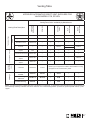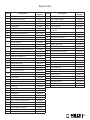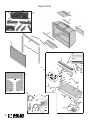
1
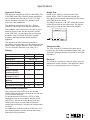
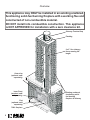
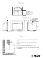
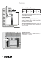
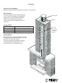
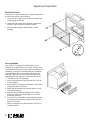
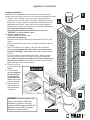
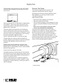
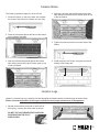
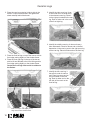
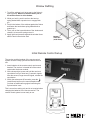
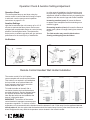
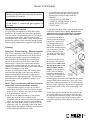
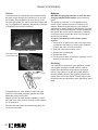
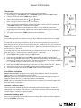
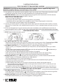
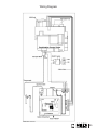
LEGEND Direct Vent Gas Insert 739ILN (NG) & 739ILP (LPG) Installation & Operating Instructions INSTALLER: Leave this manual with the appliance. CONSUMER: Retain this manual for future reference. PLEASE READ THIS MANUAL BEFORE INSTALLING AND OPERATING THIS APPLIANCE. WARNING: If the information in these instructions is not followed exactly, a fire or explosion may result causing property damage, personal injury or loss of life. Do not store or use gasoline or other flammable vapors and liquids in the vicinity of this or any other appliance. WHAT TO DO IF YOU SMELL GAS • Do not try to light the appliance. • Do not touch any electrical switch; do not use any phone in your building. • Immediately call your gas supplier from a neighbor’s phone. Follow the gas supplier’s instructions. • If you cannot reach your gas supplier, call the fire department. This appliance may be installed in an after-market permanently located, manufactured (mobile) home where not prohibited by local codes. This appliance is only for use with the type of gas indicated on the rating plate. This appliance is not convertible for use with other gases, unless a certified kit is used. This appliance is a domestic room-heating appliance. It must not be used for any other purposes such as drying clothes, etc. This appliance is suitable for installation in a bedroom or bed sitting room. Massachusetts: The piping and final gas connection must be performed by a licensed plumber or gas fitter in the State of Massachusetts. Installation and service must be performed by a qualified installer, service agency or the gas supplier. Manufactured by MILES INDUSTRIES LTD. 00189-0 ©2008, Miles Industries Ltd. British Columbia, Canada www.valorfireplaces.com Thank You ... For purchasing a Valor by Miles Industries. Your new radiant gas heater is a technical appliance that must be installed by a qualified dealer. Each Legend is fully tested during the production process for your safety and comfort. Your unit has been professionally installed by: Dealer Name _______________________________________ Phone Number ______________________________________ Should you encounter an operational problem, call your dealer immediately. Do not try to repair the unit as you may cause an injury or damage the fireplace. The information contained in this installation manual is believed to be correct at the time of printing. Miles Industries Ltd. reserves the right to change or modify any information or specifications without notice. Miles Industries Ltd. grants no warranty, implied or stated, for the installation or maintenance of your heater, and assumes no responsibility for any consequential damage(s). We recommend that our gas hearth products be installed and serviced by professionals who are certified in the United States by NFI (National Fireplace Institute®). Designed and Manufactured by Miles Industries Ltd. 190 – 2255 Dollarton Highway, North Vancouver B.C, CANADA. V7H 3B1 Tel. 604-984-3496 Fax 604-984-0246 www.valorfireplaces.com © Copyright Miles Industries Ltd., 2008 Table of Content Safety and Warning Information...................................................................4 Specifications.................................................................................................5 Overview..........................................................................................................6 Dimensions.....................................................................................................7 Cavity...............................................................................................................7 Clearances.......................................................................................................8 Venting.............................................................................................................9 Installation Planning ...................................................................................10 Existing Fireplace Preparation ...................................................................10 Appliance Preparation..................................................................................11 Supply Gas....................................................................................................14 Ceramic Bricks..............................................................................................15 Ceramic Logs................................................................................................15 Window Refitting .........................................................................................17 Initial Remote Control Set-up......................................................................17 Operation Check & Aeration Settings Adjustment ...................................18 Remote Control Handset Wall Holder Installation.....................................18 Owner’s Information.....................................................................................19 Lighting Instructions....................................................................................24 Wiring Diagram.............................................................................................25 Options..........................................................................................................26 Venting Table.................................................................................................27 Warranty........................................................................................................28 Spare Parts....................................................................................................29 Safety and Warning Information READ and UNDERSTAND all instructions carefully before starting the installation. FAILURE TO FOLLOW these installation instructions may result in possible fire hazard and will void the warranty. Prior to the first firing of the fireplace, READ the Owner’s Information Section of this manual. DO NOT USE this appliance if any part has been under water. Immediately, CALL a qualified service technician to inspect the unit and to replace any part of the control system and any gas control that has been under water. THIS UNIT IS NOT FOR USE WITH SOLID FUEL. Installation and repair should be PERFORMED by a qualified service person. The appliance and venting system should be INSPECTED before initial use and at least annually by a professional service person. More frequent cleaning may be required due to excessive lint from carpeting, bedding, etc. It is IMPERATIVE that the unit’s control compartment, burners, and circulating air passageways BE KEPT CLEAN to provide for adequate combustion and ventilation air. Always KEEP the appliance clear and free from combustible materials, gasoline, and other flammable vapors and liquids. NEVER OBSTRUCT the flow of combustion and ventilation air. Keep the front of the appliance CLEAR of all obstacles and materials for servicing and proper operation. Due to the high temperature, the appliance should be LOCATED out of traffic areas and away from furniture and draperies. Clothing or flammable material SHOULD NOT BE PLACED on or near the appliance. Children and adults should be ALERTED to the hazards of high surface temperature and should STAY AWAY to avoid burns or clothing ignition. Young children should be CAREFULLY SUPERVISED when they are in the same room as the appliance. This unit MUST be used with a vent system as described in this installation manual. NO OTHER vent system or component MAY BE USED. This gas fireplace and vent assembly MUST be vented directly to the outside and MUST NEVER be attached to a chimney serving a separate solid fuel burning appliance. Each gas appliance MUST USE a separate vent system. Common vent systems are PROHIBITED. INSPECT the external vent cap on a regular basis to make sure that no debris is interfering with the air flow. The glass door assembly MUST be in place and sealed before the unit can be placed into safe operation. DO NOT OPERATE this appliance with the glass door removed, cracked, or broken. Replacement of the glass door should be performed by a licensed or qualified service person. DO NOT strike or slam the glass door. The glass door assembly SHALL ONLY be replaced as a complete unit, as supplied by the fireplace manufacturer. NO SUBSTITUTE material may be used. DO NOT USE abrasive cleaners on the glass door assembly. DO NOT ATTEMPT to clean the glass door when it is hot. TURN OFF THE GAS BEFORE servicing this appliance. It is recommended that a qualified service technician perform an appliance check-up at the beginning of each heating season. Any safety screen or guard removed for servicing MUST BE REPLACED before operating this appliance. DO NOT place furniture or any other combustible household objects within 36” of the fireplace front. BE CAREFUL not to put any decorating objects sensitive to heat too close to the fireplace as it gets very hot when operating. DO NOT USE this heater as a temporary source of heat during construction. State of California. Proposition 65 Warning. Fuels used in gas, wood-burning or oil fired appliances, and the products of combustion of such fuels, contain chemicals known to the State of California to cause cancer, birth defects and other reproductive harm. California Health & Safety Code Sec. 25249.6. Specifications Approval & Codes Supply Gas This appliance is certified to ANSI Z21.88b-2008 / CSA 2.33b-2008 Vented Gas Fireplace Heater standard for use in Canada and USA, and to CGA 2.17-91 High Altitude Standard in Canada. This appliance is for direct vent insert installations. Heater engine 739ILN is used with natural gas. Heater engine 739ILP is used with propane gas. The supply pressure must be between the limits shown in the Ratings section above. The supply connection is 3/8” NPT female and located on the left hand side of the control valve. The gas line entry point is on the left hand side on the fireplace. This appliance complies with CGA P.4.1 Testing method for measuring annual fireplace efficiencies. The installation must conform to local codes or, in the absence of local codes, with the National Fuel Gas Code, ANSI Z223.1 or the Natural Gas and Propane Installation Code CAN/CGA-B149. Only qualified licensed or trained personnel should install this appliance. This appliance must be electrically grounded in accordance with local codes, or, in the absence of local codes, with the National Electrical Code, ANSI/NFPA 70 or the Canadian Electrical Code, CSA C22.1. Ratings Model Gas Altitude (Ft.)* Input Maximum (Btu/h) Input Minimum (Btu/h) Manifold Pressure (in w.c.) Minimum Supply Pressure (in w.c.) Maximum Supply Pressure (in w.c.) Main Burner Injector Marking Pilot Injector Marking Min. Rate By-Pass Screw NG LPG Natural Propane 0-4,500 feet* 26,000 24,000 6,500 13,000 3.2 10.0 5.0 11.0 10.0 14.0 82-750 92-260 33 125 27 125 X X Conversion Kits The 739IL Legend G3 is supplied as natural gas or propane gas and is field convertible between fuels. See instructions packaged with the conversion kit for further information. Electrical The 739 does not require an electrical power source to operate as a heater. However, if the appliance is fitted with a fan, a grounded power source is required. *High Altitude Installations Input ratings are shown in BTU per hour and are certified without deration for elevations up to 4,500 feet (1,370 m) above sea level. For elevations above 4,500 feet (1,370 m) in USA, installations must be in accordance with the current ANSI Z223.1 and/or local codes having jurisdiction. Heating value of gas in some areas is reduced to compensate for elevation—consult your local gas utility to confirm. For installations at elevations above 4,500 feet (1,370 m) in Canada, please consult provincial and/or local authorities having jurisdiction. Overview This appliance may ONLY be installed in an existing unaltered, functioning solid-fuel burning fireplace with a working flue and constructed of non-combustible material. DO NOT install into combustible construction. This appliance is NOT APPROVED for installation with a zero clearance kit. Chimney Terminal Cap Flashing 2 x 3” flex chimney liners running full length Outer trim (optional, sold separately) Inner Front (required, sold separately) Fret (optional, sold separately) 739IL fireplace 6 Existing unaltered, functioning solidfuel burning fireplace & chimney Dimensions 28-5/8” (727 mm) 19-1/2” (495 mm) 12” (305 mm) or 12-5/8” (321 mm) Varies with outer trim options Optional Outer Trim or Surround sold separately 9-3/8” (238 mm) or 10” (254 mm) Varies with outer trim options 20” (508 mm) Gas inlet Gas connection Electrical inlet Cavity Check that masonry step does not interfere with install dimensions or vent pipe. If mantel is combustible, see section Clearances for allowable clearances. Minimum width of fireplace opening at front: 28” (711 mm) X Y X = 12” (305 mm) or 12-5/8” (321 mm)—varies with outer trim options Y = 20” (508 mm) 7 Clearances Combustible Mantel Clearances A Mantel Projection A 1” (25 mm) ” (101 mm) 8” (203 mm) 1” (355 mm) Mantel Height B* 8” (711 mm) ” (813 mm) 35” (889 mm) 8” (965 mm) *Measure taken from the underside of the mantel to finished hearth or surface that the unit is sitting on. B Finishing Materials Combustible materials: Material such as wood, compressed paper, plant fibers, plastics or any material capable of igniting and burning, whether flame-proofed or not, plastered or un-plastered. Non-combustible materials: Material such as steel, iron brick, tile, concrete or materials that bear the UL mark for zero (0) fire rating. Sidewall Clearances Minimum distance from side of appliance (liner box) to combustible wall: 9” (229 mm). 9” (229 mm) sidewall 8 Venting Typical Vent Installation See list of approved Venting Accessories on page 27 of this manual. Vent Location The vent terminal must be located through the roof. This direct vent appliance is designed to opreate when an undistrubed airflow hits the outside vent terminal from any direction. Check local codes for allowable vertical vent termination. Terminal Cap Flashing Venting Table Maximum vertical height 40 ft (measured to bottom of termination) Minimum vertical height 10 ft (measured to bottom of termination) Maximum horizontal run 4 ft (measured center to center of pipe) Maximum offset angle 45˚ (sweeping bend to allow for obstructions) 2 x 3” flex liners—see Venting Table for length allowed Venting Notes Where possible, avoid joining flex pipes. If joints are required, use a approved connector and seal joints with RTV high temp sealant. Four feet horizontal is permissible to allow for routing around masonry projections. Do not bend flex pipe over a 45 degrees radius. 9 Installation Planning Installer—READ THIS FIRST 1. YOU NEED TO KNOW FROM THE HOMEOWNER what accessories (surround, door, etc.) will be installed with this fireplace; . Unpack the appliance. . Check that you have everything. . Clean cavity and chimney. 5. Install venting pipes. 6. Attach conversion plate to existing fireplace. 7. Install and test blower if used. 8. Fit appliance into cavity. 9. Install restrictor. 10. Connect and test gas supply. 11. Install bricks and logs. 1. Refit window. 1. Connect electrical wiring blower if used. 1. Put batteries in receiver and remote control handset. 15. Verify operation and adjust aeration settings. 16. Install the remote control handset wall holder. 17. Instruct the homeowner on the operation and maintenance of the fireplace. 18. Install the surround trim and front. 19. Install the fret if required. Tools and supplies required • • • • • • • • • • Packing knife Screwdriver set Metric socket set Pliers Adjustable Wrench Sealant Dish soap/water solution Gloves Eye Protection Electric outlet if installing a blower Existing Fireplace Preparation A few points must be considered before inserting the 739IL into an existing fireplace cavity. Generally, no modifications are allowed to the existing fireplace that will compromise the integrity of the existing fireplace. Components that are bolted or screwed on such as dampers or baffles may be removed to accommodate the installation of the 739IL engine. Cutting away any sheet metal parts of the existing fireplace to accommodate the installation of the 739IL is prohibited. Check with local authorities if in doubt. Clean Fireplace and Chimney Have the chimney swept and the fireplace cavity cleaned before installing the 739IL heater and vent liners. Any creosote or soot residue remaining in the fireplace cavity or chimney may cause odors once the 739IL insert is installed. Consult with chimney sweep for information on how best to clean. Existing Dampers Factory-built, zero-clearance fireplaces will require the damper to be removed in order to install the vent liners. These dampers are usually bolted into place. Dampers in masonry fireplaces must be fixed open and may remain in place. 10 Existing Fireplace Preparation Ash Retaining Curbs Some fireplaces (particularly factory-built) have a raised curb at the front edge to retain ashes. Check the dimensions carefully to ensure the 739IL engine will fit behind any raised curb (some curbs may be removed separately from the refractory base). Gas Line Routing Plan the routing of the gas line before proceeding. Utilize the existing hole for the gas line. If the factory-built fireplace has no access hole, carefully drill an access hole of 1.5 inch (38 mm) or less through the lower sides or bottom of the firebox. The access hole must be plugged with non-combustible insulation after the gas supply line has been installed. See Dimensions section for detailed location of gas inlet. Also, take into consideration whether or not a fan or shut-off valve will interfere when planning routing of the gas line. Existing Glass Doors and Wire Screens Existing glass doors must be permanently removed prior to installing the 739IL insert. Combustible Mantels Combustible mantel clearances must conform to those required for the original solid-fuel fireplace into which the 739IL is being installed. Attach Warning Conversion Plate to Existing Fireplace (label supplied loose with 739IL heater) Attach the “This fireplace has been converted...” label to the existing fireplace using screws or other mechanical means and store any removed parts in back of the existing fireplace for future use. Appliance Preparation Unpacking the appliance Beware of sharp edges! Wear gloves! 1. Unpack the appliance. . Unpack any loose items from around the appliance and check against the Pack Content list provided in the documentation package. . Remove the window and set aside in a safe place to avoid damage—see next page. 4. Verify that you have all the components required for the installation, including: - brick panels & logs; - surround/doors/fret; - venting components and accessories; - blower and electrical components for blower installation if used. 11 Appliance Preparation Window Removal The window is held in place by four spring-loaded bolts, two at the top and two at the bottom. 1. To remove the window, turn each bolt a quarter turn to disengage the bolt pin. . Gently pull the bottom of the window outward and unhook it from the firebox’s opening frame. . Set the window aside in a safe place to avoid damage. Fan installation If the 755CFK Circulating Fan Kit (blower) is to be installed, we suggest that you do it now. The fan cavity is accessible from the back of the firebox to facilitate its installation. If the fan is retrofitted after the installation of the appliance, the burner module will need to be removed. Therefore, we recommend that the fan be installed before the appliance is fitted into the cavity. 1. Take the fan out of its package. . As per instructions provided with the fan, fit it to its mounting plate. . At the bottom of the back of the firebox, remove the rectangular plate (4 screws). . Attach the fan bracket to the firebox plate you just removed (4 screws). 5. Insert the fan attached to the plate into in firebox and fix the plate to the firebox with the 4 screws previously removed. 6. From the front of the firebox, thread the fan electric cord through the hole on the right hand side of the firebox outer shell. 7. Refer to instructions provided with the 755CFK for complete details. 12 Appliance Preparation Venting Installation IMPORTANT: This appliance’s venting system is room sealed and therefore, does not require room air to be used in the combustion process. 1. Rough-in two 3” diameter vent liners into the existing chimney system from the roof. Be careful not to tear or damage the liners in the process. It may be easier to install both liners at the same time rather than one at a time. Leave plenty of liners at the bottom to facilitate the connection of the liners to the vent slider. It is best to leave the top termination until later. Designate and mark the top and bottom of one liner as “EXHAUST” to avoid confusion later. 2. a) Large cavity opening Slide the appliance into the cavity. b) Smaller cavity opening Release the two screws retaining the vent slider to the front of the firebox. Remove the slider from the firebox by sliding it towards the back of the firebox. . Apply RTV sealant to the collars on the vent slider and fit the two liners ensuring that the exhaust liner is connected to the identified “EXHAUST” vent collar. Secure with 4 tapping screws per liner. If the vent slider was removed from the firebox, slide the firebox onto the vent slider in the cavity taking care not to damage the liners. Make sure that the rear edge of the slider is hooked over the cleat on the firebox. Secure the vent slider to the front of the firebox with two screws removed earlier. . From the roof, pull the liners and fit the flashing. 5. Fit the terminal cap ensuring that the exhaust liner is connected to the exhaust vent collar. Secure with Vent slider 8 screws provided. cleat 6. Seal the terminal and flashing from water penetration as required. 5 6 4 1 option 2b 3 WARNING: Failure to position the parts in accordance with these diagrams or failure to use only parts specifically approved with this appliance may result in property damage or personal injury. option 2a 1 Supply Gas The gas supply inlet connection is a 3/8” NPT female connector and is located on the left hand side of the control valve. Pressure Test Points The minimum supply pressure is given in the subsection Ratings of this manual—page 5. All piping and connections must be tested for leaks after installation or servicing. All leaks must be corrected immediately. When testing for leaks: X Use only new black iron or steel pipes or copper tubing if acceptable—check local codes. Note that in USA, copper tubing must be internally tinned for protection against sulfur compounds. The burner platform and gas train on this appliance may be removed as a unit for servicing or to install or remove the optional circulating fan (if installed). Provide some form of pipe union (depending on type of piping) as close as possible to appliance valve. Unions in gas lines should be of ground joint type. The gas supply line must be sized and installed to provide a supply of gas sufficient to meet the maximum demand of the appliance without undue loss of pressure. • Make sure that the appliance is turned off. • Open the manual shut-off valve. • Test for leaks by applying a liquid detergent or soap solution to all joints. Bubbles forming indicate a gas leak. Never use an open flame to check for leaks. Correct any leak detected immediately. The pressure test tapping locations are shown in the figures on the below. An internal regulator within the valve controls the burner manifold pressure. The correct pressure range is shown in the table in subsection Ratings of this manual on page 5. The pressure check should be made with the burner alight and at its highest setting. See Lighting Instructions section for full operating details on page 24. Sealant used must be resistant to the action of all gas constituents including LP gas. Sealant should be applied lightly to male threads to ensure excess sealant does not enter gas lines. Pressure test the supply line for leaks. The appliance and its individual shut-off valve must be disconnected from the gas supply piping system during any pressure testing of that system at test pressures in excess of 1/2 psig (3.5 kPa). Failure to either disconnect or isolate the appliance during pressure testing may resultin regulator or valve damages and void the warranty. Consult your dealer in case of damages. Pressure Testing 14 Ceramic Bricks The following guidelines apply for all brick liners. 1. Inside the firebox, on the top of each side, release the screw of the side brick anchors (one per side). . Slide the right hand side panel against the firebox side making sure that the brick anchor goes on top of the brick panel. . Place the rear panel against the back of the firebox, on the retainer at bottom. 5. Tighten the side brick anchors on each side of the firebox. . Slide the left hand side panel against the firebox side making sure that the brick anchor goes on top of the brick panel. 6. Install the port cover fixing it using the two screws already in the firebox top. Ceramic Logs Unpack he ceramic logs very carefully to avoid damaging the fragile material. Install the logs as shown below. Please note that the position of the Logs is critical to insure proper performance of the appliance. 1. Spread the decorative charcoals on each side of the log tray, covering the sheet metal as shown. DO NOT PUT ANY DECORATIVE CHARCOAL PIECES WITHIN THE PILOT SHIELD AREA. 15 Ceramic Logs . Place the rear log centering it side to side in the firebox. Position forward until it sits against the sheet metal lip behind the burner. 5. Identify the right cross log; it has a hole under on of its ends and it is the shortest cross log. Place it on the right pin located on the rear log. Rest its other end in the crook of the front right log. 6. Identify the middle cross log. It does not have a hole underneath. Place its narrow end on the flat depression in the rear log next to the right cross log on the rear log. Place its wider end on the front log. . Place the front left log on top of the burner with its front edge resting slightly on the window frame. . Place the front right log on the top of the burner with its left end abutted to the front left log and its front edge resting slightly on the window frame. Center the front logs side to side in relation to the firebox. 7. Identify the left cross log; it has a hole under its narrow end. Place its narrow end on the pin located on the rear log. Rest its wider end on the left side of the crook on the front left log. Both front logs to rest slightly on the edge of the firebox window frame. 16 Window Refitting 1. To refit the window, hook its top part to the firebox’s opening frame. Make sure that the wider part of the window frame is at the bottom. . While you hold it, push in and turn the two top spring-loaded bolts a quarter turn to engage their pin. . Push in the bottom of the window against the firebox and fasten the two bottom spring-loaded bolts a quarter turn. . Then, pull out the top and bottom of the window and release it to insure the springs return it. 5. Apply light hand pressure against the window frame sides to bed-in the window seal. Bottom of window (wider frame) Initial Remote Control Set-up The receiver and the handset of the remote control system must be initially synchronized before the first use. 1. Insert batteries in the remote control receiver and handset. The receiver is located left of the control valve under the burner module. . With a sharp object, press and hold the receiver’s reset button until you hear two (2) acoustic signals. After the second, longer acoustic signal, release the reset button. . Within the subsequent 20 seconds, press the (small flame) button on the remote handset until you hear an additional long signal confirming the sychronization is set. This is a one time setting only and is not required when changing the batteries in the remote receiver. The remote control system is now ready to use. 17 Operation Check & Aeration Settings Adjustment Operation Check Turn the fireplace flame up and down using the remote control to confirm that the full range of inputs is achieved—see the remote control operation instructions on pages 21–23. Aeration Settings Light the fire and allow the unit to warm up for 10–15 minutes to evaluate the flame picture. Burners are equipped with an adjustable shutter to control primary aeration. See the figures below. The shutters are factory-set to an aeration gap which will give optimum performance for the vast majority of installations. In a few unusual installations, the flame picture may be improved by adjusting the aeration. The need for adjustment should be determined only by operating the appliance with the ceramic logs and window installed. Increasing aeration (open) will cause the flames to appear more transparent and blue showing more ceramic log glow. Decreasing aeration (close) will cause the flames to appear more yellow or orange showing less ceramic log glow. Too little aeration may result in black carbon forming and dropping into the firebox. Air Shutters LPG NG Air Shutter Air Shutter Sliders Flashback shield Close Open Air Shutter Slider Close Open Remote Control Handset Wall Holder Installation The remote control kit for this fireplace Alternative 2 Alternative 3 Packing Contents: comes complete with a wall-mounted holder. 1 Wall Bracket A This holder is not required in all installations 2 Screws B but is provided as an optional feature for 1 Screw C those customers who wish to mount the 2 Wall Anchor D remote handset to the wall. 1 Spacer E (detach before assembly) To install the holder to the wall, find a Switch Plate convenient location and use the hardware 1 Wall Bracket F provided with the kit. See the diagram below Alternative 1 for required hardware and configurations. Note that the holder can be installed at the base of a light switch plate. IMPORTANT. The location of the remote control handset is important to assure proper temperature regulation. To obtain a constant temperature, we recommend that the handset should be between 3 and 15 feet away from the appliance but not directly above it. We also advise that the handset should be located away from any other heat source and not in direct sunlight as this may affect the temperature sensor located in the remote handset. 18 Owner’s Information WARNING: Your fireplace becomes very hot when operating. Avoid placing decorating objects sensitive to heat within 36” around it. Performance of LPG appliances may be affected by the quality of commercial gas supplied in your area. Operating Your Fireplace For your safety, this appliance is fitted with a flame supervision device which will shut-off the gas supply if, for any reason, the pilot flame goes out. This device incorporates a fixed probe, which senses the heat from the pilot flame. If the probe is cool, the device will prevent any gas flow unless manually lighting the pilot. See full lighting instructions on page 24 of this manual. Cleaning Important - Glass cleaning - Mineral deposits One of the by-products of the combustion process in a gas appliance is a mineral which can show up as a white film on the ceramic glass of the viewing door. The composition of the deposit varies widely from various locations and also from time to time in the same location. It seems this is associated with the varying sulfur content of the gas. You may have the problem for a time and then not see it for many months when it will reappear in your area. We have discussed this problem with ceramic glass manufacturers and they cannot give us a definitive answer to this problem. Dealers have tried various cleaning products with varying results. The following recommendations will not guarantee results in your particular case. NOTE: This is a problem beyond Miles Industries’ control and is not covered under warranty. 1. Clean the glass regularly as soon as you notice the buildup (white film). If the film is left for a longer period of time, it will bake on. It is then much harder, if not impossible, to remove. . NEVER use an abrasive cleaner on the ceramic glass. Any abrasion of the surface has the immediate effect of compromising the strength of the glass. An emulsion type cleaner is recommended. . Use a soft damp cloth to apply the cleaner. Dry the glass with a soft, dry, preferably cotton cloth. Most paper towels and synthetic materials are abrasive to ceramic glass and should be avoided. . Our dealers have had good results from the products listed below. We cannot, however, guarantee the results of these products. • BRASSO • POLISH PLUS by KEL KEM • COOK TOP CLEAN CREME by ELCO • WHITE OFF by RUTLAND • TURTLE WAX Do not clean the glass while it is hot. Always securely replace the window before lighting. If broken, the glass pane may only be replaced as a complete window unit as supplied by the manufacturer. To remove the window for cleaning, turn each springloaded bolt a quarter turn to disengage the bolt pin. Gently pull the bottom of the window outward and lift it up to unhook it from the firebox’s opening frame. Set aside in a safe place to avoid damage—see page 12. To refit the window, hook its top part to the firebox’s opening frame. Make sure that the wider part of the window frame is at the bottom. While you hold it, push in and turn the two top spring-loaded bolts a Bottom of window quarter turn to engage their (wider frame) pin. Push the bottom of the window against the firebox and fasten the two bottom spring-loaded bolts a quarter turn. Then, pull out the top of the window and release it to insure the springs return it. Finally, apply light hand pressure against the window frame sides to bed-in the window seal—see page 17. Soot or dust can be brushed from the ceramic logs and firebox walls using a soft brush. Dust can also be removed from the burner using a soft brush after removing the ceramic logs. When cleaning, make sure that no particles are brushed into the slots of the burner. 19 Owner’s Information Checks Batteries A periodic check of the pilot and burner flames should be made. Check after the fire has been on for at least 30 minutes. The pilot flame must cover the tip of the thermocouple probe. The main burner flame pattern will vary from appliance to appliance depending on the type of installation and climatic conditions. BEFORE changing the batteries, turn off the valve using the manual On/Off switch—see instructions below. The appliance uses four 1.5 V AA batteries for its remote control receiver and one 9 V battery for its handset. Batteries should last one to two seasons, depending on usage. Removing the batteries in the offseason will extend the battery life. Should the batteries lose power, the control may be operated by manually turning the control knob at the valve or by turning off the valve at the switch. To replace the batteries in the remote control receiver: 1. The receiver is located to the left of the valve and it is retained to the firebox by a Velcro tab. Grab the receiver and pull it out from its location. . Slide and remove the receiver cover. . Replace the 4 AA batteries. . Replace the cover. 5. Put the receiver back in its position pushing it in so it attaches to the Velcro tab. Correct Flame Picture Pilot Flame can be seen between logs Servicing Pilot Flame The appliance area must always be kept clear and free from combustible materials, gasoline and other flammable vapors and liquids. Inspect the vent terminal outdoors regularly to make sure that snow, trees, bushes, leaves, or other objects do not obstruct it. Examine the vent system and terminal regularly. We recommend annually. 20 If any attention is required for your appliance, contact your supplier quoting the model number. It will be helpful if the appliance’s serial number can also be quoted. This number is on the rating plate, which is located under the burner. The replacement parts are shown at the end of this manual. Please always quote the part number and description when requesting spare parts. Owner’s Information Manual On/Off Switch In cases where you want to turn off your fireplace and cannot do it with the remote control handset (misplaced, lost, dead batteries, etc.) or if you need to replace the receiver’s batteries, you can turn off the appliance with the manual switch located on the right hand side of the valve. If the 1265WSK Wall switch is installed and the remote control will not be used, remove the battery from the handset and store it away. If you are planning not to use your fireplace for a prolonged period of time, remove the battery from the remote handset and turn off the gas valve using the manual ON/OFF switch. ON OFF Remote Control Operation NOTE: Before using the remote control system for the first time, the receiver and the handset must be synchronized. See the section Initial Remote Control Set-up on page 17 in this manual. Your fireplace remote control helps you get the comfort, convenience and aesthetics you want from your gas fireplace. The remote controls your fireplace in different ways. IMPORTANT: BEFORE YOU BEGIN, please note that on this system, the settings of time, temperature and automatic ON/OFF can only be programmed when the function display is flashing. Be patient when programming as it can take a few seconds to set. Turning your fireplace ON WARNING: When the pilot is lit, the valve motor turns automatically to maximum flame height. 1. Make sure that the MAN knob on the valve is in ON position. . Make sure that the switch on the valve is in the I position. Press and hold the OFF and (large flame) buttons until you hear a short acoustic signal. Release the buttons. The acoustic signals will continue until the pilot lights. The remote control will go automatically into TEMP mode. The flame will be at maximum height until the remote control reads the temperature (factory set) and will then adjust the flame accordingly. You can put the remote in MAN manual mode, change the temperature in TEMP mode or program your remote in TIMER mode as indicated in the following sections. Turning your fireplace OFF 1. Press the (small flame) button to reduce the flame to pilot. . Press the OFF button to turn the pilot off. Alternately, you can press the O button on the switch if you won’t use your fireplace for a long period of time, if you cannot locate your remote control handset or if you wish to change the batteries. 21 Owner’s Information Operation Modes STANDBY MODE—Ignited pilot only. man MAN MODE—Manual Mode. You can use this mode to adjust the flame height up or down. ☼temp TEMP MODE—Daytime Temperature Mode (appliance must be in Standby mode; pilot ignited): The room temperature is measured and compared to the set temperature. The flame height is then automatically adjusted to achieve the Daytime set temperature. ☽temp TEMP MODE—Nighttime Setback Temperature Mode (appliance must be in Standby mode, pilot ignited): The room temperature is measured and compared to the Nighttime Setback temperature. The flame height is then automatically adjusted to achieve the Nighttime Setback temperature. TIMER MODE—(appliance must be in Standby mode, pilot ignited): The Timer setting allows you to set two burner ON times and two burner OFF times for every 24-hour period. timer Changing the Mode of Operation Briefly pressing the SET button changes the mode of operation in the following order: → → → → ☼temp ☽temp timer and back to man. NOTE: MAN mode can also be reached by pressing either the or man buttons. In TEMP mode, ☼ indicates the daytime temperature setting. ☽ indicates the nighttime temperature setting. In TIMER mode, ☼ indicates the start time setting. ☽ indicates the stop time setting. Flame Height The flame height can be adjusted in the following manners. In STANDBY mode, 1. Press the . Press the . Press the (large flame) button to turn on the main burner. (small flame) button to increase the flame height. (small flame) button to decrease the flame height or to go to pilot Standby position. For fine adjustments, tap the and buttons. Quick Flame Adjustment If or are pressed for 0.5 sec., the flame will increase to maximum or decrease to the pilot Standby position. NOTE: While pressing either button, a symbol indicating transmission appears on the upper right hand corner of the display. The receiver confirms transmission with an acoustic signal. Time To set the time, follow the steps below. 1. The display indicates °C/24-hour or °F/12-hour clock. To change from one to the other, press and hold both the OFF and buttons until the display changes. . To set the time, hold down both the and buttons until the display flashes. Let go. . Quickly press the button to set the hour and the button to set the minutes. Note: You must start setting the time while the display is flashing. If it stops flashing, go back to 2. . Press the OFF button to return to manual mode or simply wait and it will automatically return to Manual mode. 22 Owner’s Information Temperature Use this setting when you come in and want to enjoy a set temperature. 1. Select either the ☼temp MODE or the ☽temp MODE by briefly pressing the SET button. . Hold the SET button until the TEMP display flashes. . Set the desired temperature with the or the buttons. Note: 4.5°C/40°F is the minimum temperature setting. . Press the OFF button or simply wait and the display will go to the temperature control mode. Note: If you would like the Nighttime Setback temperature control to turn off, decrease the ☽temp MODE setting until [---] appears on the display. Your fireplace will reach the set temperatures and the remote handset will check the temperature every five minutes, adjusting the amount of fuel needed to give you a steady, even heat. 5. The display must remain in TEMP mode on the remote handset. Timer It is possible to program two periods of time per day at which your fireplace will turn on and off automatically. For example, you can set your fireplace to turn on in the morning just before you get up (P1 ☼ [start time]) and to turn off when you leave for the day (P1 ☽ [stop time]). Then, you can set your fireplace to turn on again at the end of the day (P2 ☼ [start time]) and to turn off when you go to bed at night (P2 ☽ [stop time]). If you wish to set only one time period at which your fireplace will turn on and off, program P2 ☼ [start time] and P2 ☽ [stop time] for the same time as P1 ☽ [stop time]. 1. Select timer mode by briefly pressing the SET button. . Press and hold the SET button until TIMER is displayed on the lower right hand side. . Press and hold the SET button until P1 ☼ and the time display flashes. Set the start time by pressing the button for the hour and the button for the minutes. Then, briefly press SET to P1 ☽ and set the stop time in the same manner you just set P1 ☼. . Briefly press the SET button again for the next burner cycle time, which will be P2 ☼ and P2 ☽. 5. Once all four times are set, press OFF or simply wait to complete programming. 6. The remote handset must remain in TIMER mode to function automatically. Low Battery Indication Remote handset: BATT will appear on the display when the battery needs to be replaced. Replace with one 9 V battery (alkaline recommended). Receiver: Three short ‘beeps’ will sound when the motor turns when the batteries need to be replaced. Replace with four 1.5 V batteries (alkaline recommended). NOTE: With very low battery, the valve shuts off the fire completely. This does not happen when the power supply is interrupted. Handset / Receiver Match The remote control handset and receiver are programmed to function together. In case of a replacement of the handset or the receiver, you will need to reset the receiver to allow them to function together. Contact your dealer for details Automatic Standby Mode If there is no transmission from the handset to the receiver within a 6-hour period, the appliance will go to Standby (pilot) mode. 23 Lighting Instructions For your safety, read before lighting warning: If you do not follow these instructions exactly, a fire or explosion may result causing property damage, personal injury or loss of life. A. This appliance has a pilot which must be lighted by hand or by remote control. Follow these instructions exactly. To save gas, turn the pilot off when not using the appliance for a prolonged period of time. B. BEFORE LIGHTING, smell all around the appliance area for gas. Be sure to smell next to the floor because some gases are heavier than air and will settle on the floor. WHAT TO DO IF YOU SMELL GAS • Do not try to light any appliance. • Do not touch any electric switch; do not use any phone in your building. • Immediately call your gas supplier from a neighbor’s phone. Follow the gas supplier’s instructions. • If you cannot reach your gas supplier, call the fire department. C. Use only your hand to push in or turn the control knobs. Never use tools. If the knobs will not push in or turn by hand, don’t try to repair them; call a qualified service technician. Force or attempted repair may result in a fire or explosion. D. Do not use this appliance if any part has been under water. Immediately call a qualified service technician to inspect the appliance and to replace any part of the control system and any gas control, which has been under water. LIGHTING INSTRUCTIONS 1. STOP! Read the safety information above. Fig 1 5 Fig 2 Fig 3 2. SET ON/OFF SWITCH (1) TO “OFF” POSITION. • Wait five (5) minutes to clear out any gas, then smell for gas, including near the floor. If you smell gas, STOP! Follow “B” in the safety information above on this label. If you don’t smell gas, go to the next step. 3. AUTOMATIC IGNITION (Fig. 1): Locate the pilot (Fig. 3.) inside of firebox at left hand side. • ON/OFF switch (1) in ON position, MAN-knob (2) in ON position; set Flame Adjustment knob (3) to lowest setting (). • On the remote control handset, press the OFF button (red dot) and large flame button ( ) simultaneously; a short acoustic signal confirms the start has begun. • Further short acoustic signals indicate the ignition process is in progress. • When the pilot is lit, the Flame Adjustment knob (3) will automatically rotate to the highest setting. • Press the small flame button ( ) on the remote control handset to reduce the flame height. 4. MANUAL IGNITION (Fig. 2): With the window off, locate the pilot (Fig. 3) inside of firebox at left hand side. • ON/OFF switch (1) in ON position, MAN-knob (2) in MAN position. • Set Flame Adjustment knob (3) to the lowest setting (). • Push down the metallic core (4) with a pen or similar instrument; this will establish the pilot gas flow. • Light gas at the pilot (5) with a match. • Continue holding down metal core (4) for about 10 seconds; after release, pilot should remain lit. • If the pilot will not stay lit after several tries, turn the gas control knob (3) to OFF () and call your local service technician or gas supplier. • Reinstall the window and set the MAN-knob (2) to ON; turn Flame Adjustment knob (3) up () or down () manually or use the flame buttons ( )( ) buttons on the remote control handset to adjust the flame height. TO TURN OFF GAS TO APPLIANCE 1. AUTOMATIC SHUT-OFF (using the remote control handset): • Press and hold the small flame button ( ) on the remote control handset to shut-off the main burner gas flow. • Press OFF button on remote handset to shut-off the appliance, including pilot flame. 2. MANUAL SHUT-OFF (using only the ON/OFF switch (1) located to the right hand side of the valve): • Press O the ON/OFF switch (1) to shut-off the appliance, including pilot flame. 24 Wiring Diagram 25 Options Venting (required) Hearth Gate (optional) See approved venting accessories listed on page 27. Hearth gates such as Kidco’s are available at retail stores carrying safety products for children. Inner Front (required) See your dealer for your choice of Inner Fronts. Outer Surrounds, Trims & Frets (optional) See your dealer for your choice of Outer Surrounds and Trims and Frets. Optional Accessories 755CFK—Fan Kit 1265WSK—Wall Switch Control Kit 759EL—Enamel Liner Conversion Kit (optional) 739PCK—Conversion Kit to Propane Gas 739NCK—Conversion Kit to Natural Gas 26 Venting Table APPROVED ALTERNATIVE DIRECT VENT SUPPLIERS FOR VALOR MODELS 739, RF24DV SIMPSON DURA-VENT SELKIRK SECURE VENT RLH INDUSTRIES MILES INDUSTRIES Venting Parts Code / availability by Manufacturer Standard Co-axial 46DVA-VC 4DT-VC — — HSDV4658-1313 — High Wind Co-axial 46DVA-VCH — — SV4CGV — — Extended Co-axial 46DVA-VCE — — — — — Co-linear — — — 3PDVCV Universal Adapter 3” Flex Coupler 2150 — — — — — Co-linear Flex Connector 46DVA-ADF — — — — — Co-axial-to-Co-linear Adapter 46DVA-GCL — — — — 556CLA Co-linear-to-Co-axial Adapter 46DVA-GK — — — — — 3” diameter 2280 Series 3” ACFL Roof Flashing 0/12-6/12 46DVA-F6 4DT-AF6 — SV4FA — — Roof Flashing 7/12-12/12 46DVA-F12 4DT-AF12 — SV4B — — Flat Roof Flashing 46DVA-FF — — SV4F — — Flashings Vertical Aluminum Flexible Liner Vent Adapters / Couplers Termination Caps Venting Parts Description HS-C33U-99 HS-C33F-1313 559CLT NOTE: 2-ply liner approved to CAN/ULC S635 suitable for venting gas appliances. As manufactured by Z-Flex. Notes: 1) Follow instructions supplied with each manufacturer’s components. 2) Termination caps manufactured by RLH Industries are from Homestyle Chimney Collection and can be ordered in one of the following finishes: a) aluminum; b) black powder coated; c) solid copper. 27 WA TY N A RR M GR A O PR T LOR OR If you have a problem with this unit, please contact your dealer or supplier immediately. Under no circumstances should you attempt to service the unit in any way by yourself. The warranties in paragraphs 1 and 2 are provided only to the first purchaser/user of this unit, are not transferable and are subject to the conditions and limitations in paragraphs 3, 4 and 5. Please review the conditions and limitations carefully and strictly follow their requirements. VA Warranty CO M F 1. Extended Warranty Coverage For a period of up to ten (10) years, Miles Industries Ltd., (the “Company”) or its appointed distributor will at its option pay the initial purchaser for the repair of, or will exchange the following parts or components which are found to be defective in material or workmanship under normal conditions of use and service: Part or Component Defect Covered Maximum Warranty Period Exterior steel casing Corrosion 10 years Glass Loss of structural integrity 10 years Cast iron parts Corrosion 10 years Firebox and heat exchanger Corrosion (but not discoloration) causing loss of structural integrity 10 years 2. Two-Year Parts Warranty In addition, for two (2) years from the date of purchase, the Company, at its option, can repair or exchange all parts and components not listed above but that are found to have a bona fide defect in material or workmanship under normal conditions of use. 3. Conditions and Limitations a) The warranty registration card must be completed by the initial owner and returned to the Company within 90 days of purchase. b) Installation and maintenance must be performed by an authorized and trained dealer in accordance with the Company’s installation instructions. c) This warranty is void where installation of the unit does not conform to all applicable codes including national and local gas appliance installation codes and building and fire codes. d) The owner must comply with all operating instructions. e) The Company is not responsible for the labor costs to remove defective parts or re-install repaired or replacement parts. f) The first purchaser or user of the unit will be responsible for any shipping charges for replacement parts as well as travel time incurred by the dealer to perform the warranty work. g) This warranty applies to non-commercial use and service and is void if it is apparent that there is abuse, misuse, alteration, improper installation, accident or lack of maintenance to the unit. h) This warranty does not cover damage to the unit through: i) Improper installation, operational or environmental conditions. ii) Inadequate ventilation in the area or competition for air from other household equipment or appliances. iii) Damage due to chemicals, dampness, condensation, or sulphur in the fuel supply lines which exceeds industry standards. i) This warranty does not cover glass, log breakage or damage to the unit while in transit. j) The Company does not allow anyone to extend, alter or modify this warranty and assumes no responsibility for direct, indirect or consequential damages caused by the unit. State or provincial laws where the first purchaser or user resides may provide specific rights to extend this warranty and, if so, the Company’s sole obligation under this warranty is to provide labor and/or materials in accordance with those laws. 4. Discharge of Liability After two (2) years from the date of purchase, the Company may, at its option, fully discharge all obligations under this warranty by paying to the first purchaser/user the wholesale price of any defective parts. 5. No Other Warranty All obligations to repair this unit are defined in this warranty. Some states or provinces may specifically mandate additional warranties on the part of manufacturers, but in the absence of such specific legislation, there is no other warranty or obligation expressed or implied. 28 Spare Parts Description Part Number Code 1 Exhaust Slide Assembly 4001133 36 Olive Nut for Pilot Pipe 220K913 2 Exhaust Slide Gasket 4000176 37 Pipe—Valve to Pilot 4001838 3 Fan Closure Plate 4001136 38 Thermal Switch Retainer 4001519 4 Port Cover 4001820 39 Valve Mounting Bracket 4000141 5 Log Support 4001841 40 Switch Bracket 4001070 6 Side Bricks Anchors (2) 4001529 41 220K891 7 Top Mounting Bracket 4000136BY Valve to Main Burner Pipe Connector 8 Side Mounting Brackets (2) 4000135BY 42 Thermocurrent Interruptor 4001037 9 Window Assembly 43 GV60 Valve by-pass 125 4000873 44 Inlet Brass Connector 4000746 45 GV60 Valve Assembly 4000873X 46 Remote Control Thermostatic 4001372 47 Switch with Cable 4001036 48 Cable Interruptor 4001035 Code 10 4001378 Burner Assembly NG 4001375S Burner Assembly LPG 4001376S Burner Rail NG 4001665 Burner Rail LPG 4001666 Injector Elbow (Main Burner) NG 4000738 Injector Elbow (Main Burner) LPG 9730035 13 Air Shutter Sliders NG (2) 3000220 13a Air Shutter NG 4000682 14 Flashback Shield LPG 3000371 14a Air Shutter LPG 320B293 15 Burner Baffle 4001784 16 Burner Mounts (2) 4001678 17 Pilot Shield 4000144 11 12 Pilot Assembly NG 4000062S Pilot Assembly LPG 4000063S Pilot Injector NG—No 33 720A575 Pilot Injector LPG—No 27 720A195 20 Pilot Bracket 720A542 21 Thermocouple 4000061 22 Hooked Olive for Pilot Injector 720A196 23 Olive Nut for Pilot Pipe 420K385 24 Electrode 720A543 25 Electrode Retaining Nut 720A200 26 Pilot Gasket A 4000139 27 Pilot Mount 4000138 28 Pilot Gasket B 4000140 29 Burner Tray 4001676 30 Pipe—Valve to Main Burner 4000065 31 Burner Plate Access Panel 4001680 32 Module Gasket—Rear 4000175 33 Module Gasket—Right 4000174 34 Module Gasket—Front 4000173 35 Module Gasket—Left 4000181 18 19 Description Part Number 49 Ignition Cable 500 mm 4001039 50 Remote Control Receiver 4001188 51 Remote Control Handset 4001038 52 Wiring Harness 4001187 53 Handset Wall Holder 9000008 54 Log Set Complete 4001696 55 Rear Log 4001697 56 Front Left Log 4001699 57 Front Right Log 4001700 58 Right Cross Log 4001701 59 Middle Cross Log 4001698 60 Left Cross Log 4001772 61 Loose Coals 4001843 62 Brick Set Complete 4001515 63 Rear Brick Panel 4001811 64 Left Brick Panel 4001809 65 Right Brick Panel 4001810 29 Spare Parts 1 54 55 57 56 61 60 2 58 3 59 4 6 7 9 5 8 NG 11 LPG 15 10 12 17 62 19 22 21 23 24 18 25 26 27 28 63 37 36 64 65 13a 16 20 LPG 14 NG 13 14a 29 30 31 35 32 46 49 47 38 34 33 39 48 40 50 53 30 52 51 45 41 44 42 43